"I've looked at life from both sides now . . ."
~ Joni Mitchell1
Walls can get wet from the inside, walls can get wet from the outside. Walls can start out wet. Wet happens. Because wet happens walls need to be designed to dry. We can and should do our best to keep them from getting wet. But no matter what we do we have to accept the fact they are going to get wet. All of them are going to be wet at some point. For most walls that point is at the very beginning. For many wetting happens all the time. In any place that there is a winter almost every wall gets wet. Not usually a lot and most of the time not wet enough for long enough to matter. Every wall that sees winter and every wall that sees rain and every wall that is in a humid place that is air-conditioned gets wet. And if you do stupid stuff like irrigate your plants and garden next to your house and irrigate the wall at the same time even walls that don’t see winter, rain or are not in a humid place that is air-conditioned get wet.
Some of you might not be aware of this but we build outside? Who knew? Before there is an inside we start out with a piece of the outside and make that piece into the inside. Outside can be pretty wet. Not all the time and not in all places, but we don’t have the luxury to build in places that are dry all the time. Besides building in dry places does not save us much grief anyway. We build out of wet stuff. Concrete comes in a big truck and we pour it. What do put in the joints of gypsum board? Mud. Stucco is a wet slurry. Bricks are stuck together with wet gooey stuff. We build out of wood. Wood grows on trees. There is almost more water in the wood then there is wood in the wood at first. Then it is not unusual to fill the walls with wet ground up newspapers and cardboard that we season with salts.
Most people don’t understand that we build much of our stuff out of dead wet plants and wet rocks and then we regularly wet the stuff. With me so far? The only things missing are bows and flows of angel hair and feather canyons everywhere. So here is the deal, walls and the other stuff we build have to be able to dry and there are only two possible directions drying can happen—to the outside or to the inside.2
So which direction do we pick? Now it gets interesting. Walls can be designed to dry to the outside or to the inside or to both sides. Lots of choices, lots of possibilities. What you do depends on where you are and what you are building with.
What makes this even more interesting is that as important as drying is we also have to try to make sure the walls don’t get too wet and stay too wet for too long. You can never prevent all wetting but you sure can limit wetting or control wetting so that the assemblies can handle the wetting that occurs. The key with the prevention of wetting thing is to make sure that the prevention of wetting strategies don’t mess up the drying strategies. And here is another kicker, the more insulated the wall assemblies the more difficult this becomes. Insulation reduces heat flow and reduced heat flow reduces drying. Highly insulated wall assemblies have much lower drying potentials than poorly insulated wall assemblies. It gets worse. Newer materials don’t handle the water as well as older materials. We have been here before—check out “BSI-027: Material View of Mold” and “BSI-039: Five Things”.
Let's look at the most important thing first. More genius level stuff here - starting with the most important thing. Rain. The wall has to handle rain and has to handle it well. More wetting to walls happens with rain than any other mechanism. The good news is handling rain is easy—flash everything and control hydrostatic pressure. We have been here already as well—“BSI-038: Mind the Gap, Eh?” and “BSI-057: Hockey Pucks & Hydrostatic Pressure”. What this really means is installing a “water control layer”, integrating gravity rain shedding (“drain the rain on the plane…”) and providing an airspace between the cladding and water control layer. Let’s look at how this is done by looking at yesterday’s “old classic” wall (Figure 1) and comparing it to today’s “new classic” wall (Figure 2).
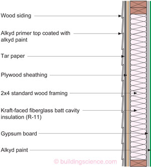
Figure 1: Yesterday’s “Old Classic” Wall - Plywood sheathing covered with tar paper over a wood frame lined with gypsum board on the inside and insulated with kraft-faced fiberglass batts. The kraft facing was really a vapor diffusion valve that opened and closed based on relative humidity. The plywood sheathing and tar paper worked the same way (see the “BSI-038: Mind the Gap” sidebar “The Magic of Plywood and the Modern Wall” and “BSI-029: Stucco Woes—The Perfect Storm Over Stucco”). So we had valves or “throttles” on both sides of the wall. Walls dried to the outside in the winter and to both sides in the summer.
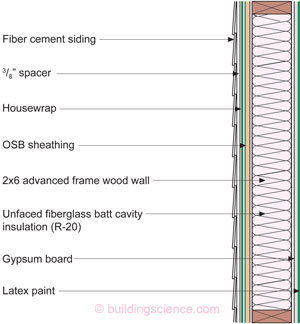
Figure 2: Today’s “New Classic” Wall - The framing goes from 2x4 framing to 2x6 advanced framing and the sheathing goes from plywood to OSB and tar paper gives way to housewraps. There needs to be an air gap between the OSB and the cladding system. The “new classic” wall can be constructed in all climate zones with only a few caveats. It can be constructed as shown in Figure 2 and comply with both the 2012 IRC and 2012 IECC in Climate Zones 1 through 5. It meets both the thermal resistance requirements in those climate zones and the vapor retarder requirements in those climate zones. You could replace the unfaced fiberglass batts shown in Figure 2 with damp spray cellulose or netted cellulose or netted fiberglass batts and still be code compliant – and more importantly the wall would still “work” from a water perspective – both rain and vapor. If you had the urge you could install kraft-faced batts (the kraft facing gives the batts a Class II vapor retarder rating) in Climate Zones 3, 4 and 5 and still be code compliant and not get into trouble with the physics. Installing a Class I vapor retarder would be a dumb idea.
Yesterday’s “old classic” wall was the workhorse wall for much of the last century. It was unbelievably robust. We know that it worked because we used it everywhere without any problems. When have you every heard of a technology to carry an industry through almost an entire century? Plywood sheathing covered with tar paper over a wood frame lined with gypsum board on the inside and insulated with kraft-faced fiberglass batts. We did not appreciate why it worked, but it worked. OK the old guys knew, but nobody was listening to them or reading their stuff.
The kraft facing was really a vapor diffusion valve that opened and closed based on relative humidity. The plywood sheathing and tar paper worked the same way (see the “BSI-038: Mind the Gap, Eh?” sidebar “The Magic of Plywood and the Modern Wall” and “BSI-029: Stucco Woes-The Perfect”). So we had valves or “throttles” on both sides of the wall. Walls dried to the outside in the winter and to both sides in the summer.
We still had a few annoying things we had to deal with the in the “old classic” wall. Mostly peeling paint on the wood siding. Thanks to the Forest Products Lab (FPL) in Madison, WI that was slam-dunked early—just no one listened or paid attention.3 Yes, same old story. Banged that drum two paragraphs earlier. Maybe there is a message there?
The FPL told us to install the wood siding over an air space, back prime the siding with oil-based primer to stop the leaching of water-soluble extractives and then top coat with something that “breathes” vapor such as a latex paint. When we did this and used latex paints over the top of oil based primers the paint could go 20 years. From 5 years to 20 years. I’d call that impressive. Vapor open interior latex paints solved the interior paint peeling problem as well. Interestingly the latex paint coatings on the inside and outside caught on, but the air gap did not.
The “new classic” wall is based on the lessons of the old classic wall. The framing goes from standard 2x4 framing to 2x6 advanced framing (yup, been here yet again—“BSI-030: Advanced Framing”), and the sheathing goes from plywood to OSB and tar paper gives way to housewraps. One huge thing needs to happen to make this wall as robust as the “old classic” wall with all these changes in materials. There must be an air gap between the OSB and the cladding system.
This air gap compensates for the different material properties between OSB and plywood, compensates for the different material properties between tar paper and housewraps (see “BSI-038: Mind the Gap, Eh?” again and “BSI-066: Holes and Leaks”), compensates for the lower drying potential due to the higher thermal resistance of the cavity insulation (see “BSI-039: Five Things”) and handles hydrostatic pressure. Even better it addresses freeze thaw concerns that may or may not be an issue with fiber cement siding.
With the air gap the “new classic” wall can dry to the outside just like the “old classic” wall did. Notice that there were no calculations here. This was figured out the old fashioned way. We kept changing things until they worked.4 Once we got it working we were able to figure out what the values were that were necessary for things to work. We know that you need a sheathing that goes between 1 perm and 3 perms as measured by a dry cup test and a wet cup test. We know that because that is what OSB does and OSB works in this assembly when there is an air gap. We know that you need a housewrap that can go between 5 perms and 50 perms because those are the properties of housewraps that work when installed over an OSB sheathing with an air gap over a heavily insulated wall.
The “new classic” wall can be constructed in all climate zones with only a few caveats. It can be constructed as shown in Figure 2 and comply with both the 2012 IRC and 2012 IECC in all Climate Zones up through 5. It meets the thermal resistance requirements in those climate zones and meets the vapor retarder requirements in those climate zones. With a vented cladding (that comes by virtue of the air gap) walls sheathed with OSB do not need a Class II interior vapor retarder under the provisions of the 2012 IRC. You could construct the same wall from 2x4 framing in Climate Zones 1 and 2 and meet the thermal resistance requirements of the 2012 IECC. You could replace the unfaced fiberglass batts shown in Figure 2 with damp spray cellulose or netted cellulose or netted fiberglass batts and still be code compliant—and more importantly the wall would still “work” from a water perspective—both rain and vapor. If you had the urge you could install kraft-faced batts (the kraft facing gives the batts a Class II vapor retarder rating) in Climate Zones 3, 4 and 5 and still be code compliant and not get into trouble with the physics. However, installing a Class I vapor retarder (like sheet polyethylene) would be a dumb idea. More on that later.
The “new classic” wall handles everything the “old classic” wall handled—but only up to and including IECC Climate Zone 5. You can build this “new classic” wall outside out of wet stuff and rain on it, air-condition it, heat it and irrigate it and it will still survive.
Once you get to IECC Climate Zones 6, 7 & 8 things change. You need to install at least R-5 continuous exterior insulation over the 2x6 framing to meet the thermal requirements of the 2012 IECC. And you may or may not need to install an interior Class II or Class I vapor retarder depending on stuff we still need to talk about.
The easy answer to meet the thermal requirements of the 2012 IECC and the vapor retarder requirements of the 2012 IRC is to install any R-5 insulating sheathing on the outside of the wall framing and install a kraft-faced fiberglass batt inside the frame cavity. We are done. The Class II vapor retarder characteristics of the kraft facing on the fiberglass batts (under “dry cup” conditions) throttles down the inward to outward vapor flow sufficiently to keep the wall assembly out of trouble from a vapor perspective during the winter and yet still allows inward drying during the summer.
Note that I said this works from a “vapor perspective”. Let’s talk rain now. If I use a foam-based sheathing to provide the R-5 continuous insulation and tape the joints I can use the foam sheathing as a water control layer. Don’t forget the gap between the cladding and the exterior face of the taped R-5 insulating sheathing to control hydrostatic pressure (Figure 3). And we are done.
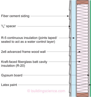
Figure 3: Foam Sheathing Wall Assembly - Foam sheathing can be used to provide the R-5 continuous insulation called for by the 2012 IECC in Climate Zones 6, 7 and 8. If the joints in the foam sheathing are taped the foam sheathing can act as a water control layer. Don’t forget the gap between the cladding and the exterior face of the taped R-5 insulating sheathing to control hydrostatic pressure.
Or are we? We are only done if we have not installed the taped continuous insulation over OSB sheathing. What if I want to use OSB sheathing for structural reasons? Or what if I want to use OSB sheathing to support a housewrap for water control reasons? Or what if I want to use taped or sealed OSB sheathing as a water control layer and air control layer?
The issue is the ability of the OSB sheathing to either dry outwards or inwards. When an impermeable or low permeable insulating sheathing is used outward drying is restricted. If inward drying is also not restricted then this is not an issue. But if inward drying is restricted by installing an interior vapor barrier such as high density spray polyurethane foam (SPF) or sheet polyethylene then this becomes an issue. We have learned from our Vancouver work (see “BSI-058: Parthenon, Eh?”) that we can get effective moisture redistribution and buffering and some outward drying by providing a small gap between the OSB sheathing and the impermeable or low permeable insulating sheathing. This gap can be provided by installing a “draining” housewrap or by installing vertical strips of sheathing tape over the exterior face of the OSB sheathing on 24-inch centers (i.e. over studs) (Figure 4). The tape thickness should be limited to around 1/8-inch thick (3 mm) so that the thermal performance of the foam sheathing is negligibly affected.
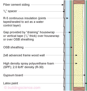
Figure 4: Vapor Impermeable Foam Sheathing Installed Over OSB with High Density Spray Polyurethane Foam - The issue is the ability of the OSB sheathing to either dry outwards or inwards. When an impermeable or low permeable insulating sheathing is used outward drying is restricted. If inward drying is also not restricted then this is not an issue. But if inward drying is restricted by installing an interior vapor barrier such as high density spray polyurethane foam (SPF) then this becomes an issue.
When using a “draining” housewrap for this purpose the housewrap does not need to act as the water control layer—it can be used for its “spacer” characteristics. For example, it is typical to use OSB at corners to provide shear resistance and use insulating sheathing in the field of the wall. A thinner layer of insulating sheathing is installed over the OSB. Housewrap can be used as a spacer and only installed over the OSB and not the rest of the wall.
Many builders choose to sheath their entire building with OSB and then cover all the OSB with rigid insulation. Using a draining housewrap over the entire building under the rigid insulation provides both a “gap” and a water control layer. Note that in all these cases a gap is required between the cladding and the insulating sheathing.
But why even use a impermeable or low permeable insulating sheathing? Why not use a vapor open insulating sheathing? Yup. Good idea. We can use stone wool or rock wool or rigid fiberglass board insulation as the continuous layer. You still need a gap between the cladding and the exterior face of this vapor open insulating sheathing. And you need a water control layer between the OSB sheathing and vapor open insulating sheathing (Figure 5) or you need to use an OSB where the water control layer is integral with the OSB sheathing where taping the joints provides water control layer continuity (Photograph 1).
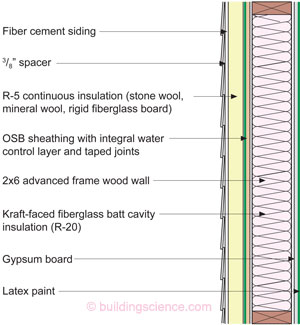
Figure 5: Vapor Permeable Insulating Sheathing Installed Over OSB - Stone wool or rock wool or rigid fiberglass board insulation can be used to provide the R-5 continuous insulation called for by the 2012 IECC in Climate Zones 6, 7 and 8. You still need a gap between the cladding and the exterior face of this vapor open insulating sheathing. And you need a water control layer between the OSB sheathing and vapor open insulating sheathing or you need to use an OSB where the water control layer is integral with the OSB sheathing where taping the joints provides water control layer continuity.
Photograph 1: OSB Water Control Layer – OSB where the water control layer is integral with the OSB sheathing where taping the joints provides water control layer continuity.
Are we done yet? Not by a long shot. What if we don’t want to use kraft-faced fiberglass. What if we want to use cellulose? Or netted fiberglass? Why not just install a plastic vapor barrier on the inside? Well that would be dumb as we now would have sort of a “double” vapor barrier—one on the outside and one on the inside. It would be legal—but dumb. Legal as in code compliant. Dumb as in risky from the moisture dynamics. The plastic sheet gives us a Class I vapor retarder (aka “vapor barrier”). We really need a Class II vapor retarder. Note that I used the words “sort of” when referring to the double vapor barrier. With the small gap between the OSB and the rigid insulation have some redistribution of moisture and some outward drying—but not a lot and not enough to be able to live with an interior vapor barrier.
Are there any commercially available Class II vapor retarders that work like the kraft facing on a fiberglass batt? Actually, yes. One is called a “smart vapor barrier”. It is a sheet good product that comes in large rolls that can be installed between the interior gypsum board and the frame wall. This allows all those other cavity insulations to be used with the R-5 continuous insulation on the exterior as we have been discussing. Another is specially formulated latex paint. You can install a paint applied Class II vapor retarder over the interior gypsum board.
But what if I don’t want to use a “smart vapor barrier” or a vapor retarder paint? What are my options? Easy. Increase the thermal resistance of the insulating sheathing. The 2012 IRC has a table that provides the necessary thermal resistances (Table 1). The values in the table are based on the curves from “BSI-049: Confusion About Diffusion”, (Figure 6).
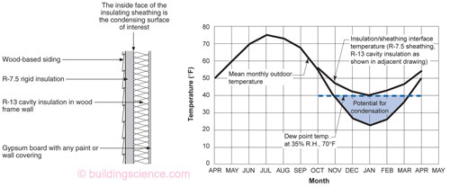
Figure 6: Insulating Sheathing Rocks - The insulating sheathing raises the temperature of the condensing surface of interest. This is a good thing. You need to follow the requirements in Table 1 in order to avoid having to install a Class I or Class II vapor retarder on the inside of the assembly.
There are few things that need to be said about these curves. We use average monthly temperatures to get the curves. Monthly averages work for moisture analysis. How do we know that? Old guys told us. Guess what? About 15 years ago bunch of young guys didn’t believe the old guys. I was sort of a young guy then. I was the oldest young guy running around with a bunch of really smart younger guys who thought they knew stuff. We built a whole bunch of test huts with all kinds or walls in all the climate zones. We wetted the walls. We watched some of them dry and some of them not. We made them air leaky and we made them reasonably tight. We varied interior moisture levels. We did this for a couple of years and guess what? The old guys were right. Again.
So how do we know what the temperature of the cavity side of the insulating sheathing (“condensing surface of interest”) should be in each of the climate zones? Ah. Easy once you know the answer. The test huts and the years of looking at real walls gave us the information we needed.
Turns out that you can get really close to the right answer if you average the average temperature of the 3 coldest months in the location of interest. If the location of interest is in Climate Zone 5 you make sure that the interface temperature stays above 35 degrees F when the interior temperature is 70 degrees F and where the outside temperature is the average temperature of the 3 coldest months. You have to realize the calculation is just a way to get you to the right amount of thermal resistance based on the real physics that came from real measurements in real experiments in the real world. But the curves and the presentation give most folks an insight as to how things work. Note that this simple calculation “tool” factors in vapor diffusion and air leakage and “incidental” wetting events. It is not a “dew point” calculation so therefore it is useful.
We used the “real world” to “tune” a simple calculation tool that could be used to provide design input. In between we developed a really complex “research” tool that we used the “real world” to tune. This tool is known as WUFI.5 This tool is very good but also very limited. It is only good in the real world range we looked at. We really can’t use it out of its range of applicability. Duh. Because we just don’t know until we know. Duh. The young guys became old guys and this old guy really knows a lot about models now. Almost as much as the old guys who came before me.
Climate Zone | Framing | Rigid Insulation |
|---|---|---|
| 4C | 2x4 2x6 | 2.5 3.75 |
| 5 | 2x4 2x6 | 5 7.5 |
| 6 | 2x4 2x6 | 7.5 11.25 |
| 7 / 8 | 2x4 2x6 | 10 15 |
Note in Table 1 the R-value of the insulating sheathing increases with cavity thickness all other things being equal. Let’s say that I want my sheathing/cavity interface to stay above 35 degrees F when the outside temperature is 0 degrees F and the inside temperature is 70 degrees F. If my wall cavity has a thermal resistance of R-10 (sort of like you get with a 2x4 wall) and my insulating sheathing has a resistance of R-10 the total thermal resistance of the wall is R-20. In this case 50 percent of the thermal resistance is to the outside of the sheathing/cavity interface and 50 percent of the thermal resistance is to the inside of the sheathing/cavity interface. The temperature difference across the wall is 70 F degrees. The temperature at the interface is 35 degrees F since half the temperature difference is across the cavity insulation and half the temperature difference is across the insulating sheathing. Let’s say I now frame with 2x6’s my wall cavity now as a thermal resistance of R-20. To keep my sheathing/cavity interface at 35 degrees F or higher my insulating sheathing now has to have a thermal resistance of R-20 to keep the same 50:50 ratio. That is why the IRC has higher insulating sheathing R-value requirements for 2x6 walls compared to 2x4 walls in each of the climate zones.
Further note that this is not in conflict with the provisions of the 2012 IECC. The IECC sets the minimum level for continuous insulation for thermal performance reasons. The 2012 IRC sets the minimum levels for continuous insulation to control condensation when not using a Class I or Class II vapor retarder. These are two very different requirements.
So what am I saying here? The code has it right—the 2012 IRC—which is based on lots of real world experiments and observations and even more important—real world experience. When someone looks at the code tables and runs a simulation model and says the model shows that the table is wrong I just roll my eyes and mutter about youngsters and then smile because I was that guy once.
Footnotes
Joni Mitchell wrote “Both Sides, Now” in 1968. It was recorded by Judy Collins and most people associate the song with Ms. Collins. But make no mistake it is Joni’s song. She of course is referring to life, I am referring to walls. Go with Joni on this. She just sang in public a month or so ago in Toronto after not performing for a decade. She still had it. An impromptu thing in front of a couple of thousand folks honoring her and her music. No one thought she would just get up and sing. But she did. Magic still happens.
This is why I get paid the big bucks. Genius level stuff here. I got famous for this. Really. After more than 30 years in the business who knew that this would be my legacy: “walls should be designed to dry and they can dry only dry in two directions”. Someone else is going to have to work on roofs.
I learned my paint lessons from Bill Feist. A legend at the USDA Forest Products Laboratory. Check out this link: http://www.fpl.fs.fed.us/documnts/fplgtr/fplgtr60.pdf and learn what I learned. Bill and a couple of other FPL legends Charlie Carll and Anton tenWolde made quite a team.
- When I said “we” that means the industry. I am still amazed that it all worked out because when stuff was first manufactured and sold no one really “knew”. The history of OSB and housewraps is really a study in being very lucky and getting away with stuff. People that say otherwise never talked to the folks who knew stuff. These people knew that they didn’t know. Management did not care as long as the stuff kept selling and the money kept rolling in. Only now do I feel we have the housewrap thing is understood and the OSB thing understood. The R & D came after the deployment. Not generally a good way to do things. We have a pretty sophisticated understanding now coupled with pretty sophisticated OSB and housewraps but it was not always so.
- A hygrothermal computer model from Oak Ridge National Laboratory (ORNL) and Fraunhofer IBP.