After one hundred and fifty years the Illinois cottage1 is undergoing some pretty interesting changes and the ghosts of George Washington Snow and Augustine Taylor2 are cautiously eyeing the result.
The current industry standard wall – a 2x4 frame at 16-inch centers with double top plates, three stud corners, jack studs, cripples and double headers – is being replaced by a 2x6 frame at 24-inch centers with single top plates, two stud corners, no jack studs, no cripples and single headers (and in many cases no headers at all).3
It is cheaper and faster to build and saves energy. What is not to like? It is cheaper because it uses 5 to 10 percent less lumber (board-feet) and it is faster because it uses 30 percent fewer pieces. It saves energy because it provides a 60 percent deeper cavity (which allows 60 percent more cavity insulation) and because it reduces the framing factor from 25 percent to 15 percent.4
The framing elements are farther apart allowing easier installation of services – everything fits easier making the plumber and tin-basher happier – the electrician drills fewer holes and the insulator insulates faster because there are fewer cavities even though the cavities are wider and deeper. Everything lines up so the load paths are direct leading to fewer but stronger connections and the lines are cleaner so it just looks and feels better.5
Tastes great – less filling.
Some of the advanced frame technology goes back to the very beginnings of framing – “in-line” framing or “stack” framing where everything lines up is not new (Figure 1). But the real innovations came from a magnificent collaboration between The US Department of Housing and Urban Development (HUD) and the National Association of Home Builders Research Foundation (NAHB Research Foundation) in the 1970’s. HUD actually did research in those days.6 Out of a HUD initiative called “Operation Breakthrough” the NAHB Research Foundation delivered “optimum value engineering framing” or “OVE framing.” Today we call it “advanced framing.” Why the name changed no one knows.7
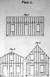
Figure 1: In-line Framing – Image from “The American Cottage Builder,” John Bullock, Stringer and Townsend, New York, NY, 1854. Great, great granddad figured this out way back when.
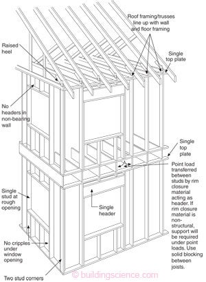
Figure 2: Advanced Framing - 2x6 frame at 24 inch centers with single top plates, two stud corners, no jack studs, no cripples and single headers in load bearing walls and no headers in non-load bearing walls.
Figure 2 shows the current expression of advanced framing. Everything lines up so that double top plates are not necessary (Photograph 1). No headers in non-load bearing walls. Window openings are clean without jack studs and cripples (Photograph 2). Exterior corners have two studs (Photograph 3). Gypsum board is supported with “drywall clips” (Photograph 4). And all of this is code accepted by the model building codes courtesy of a whole bunch for foresight by HUD and the NAHB in the early 1980’s. Although it’s in the code most code officials are not aware of it and even fewer builders. And engineers? Talk about an information disconnect. The push back from structural engineers centers mainly around the fact that with advanced framing they would be required to do something they hadn’t done since graduation – a calculation. Yup, now they would have to deal with different values not found in tables. They would have to look at a textbook and re-program the computer.
Photograph 1: Stack Framing - Everything lines up so that double top plates are not necessary.
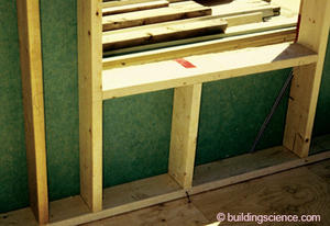
Photograph 2: Window Opening - Non-load bearing wall window openings are clean without jack studs and cripples.
Photograph 3: Corner Framing - My first advanced frame building in 1982 using a two-stud corner.
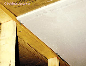
Photograph 4: Gypsum Board Support – Drywall clips result in floating corners, a good thing, as drywall cracking is reduced.
One of the biggest pushback’s from builders and code officials comes from corner support for gypsum board and trim (Figure 3 and Figure 4). Explaining that “floating corners” reduce drywall cracking and are therefore an improvement takes a little bit of time. Wood always moves because of changing moisture contents. Gypsum board does not want to move – ever. When you attach something that is always moving to something that does not want to move you get a problem. We call that a crack. They key to reducing drywall cracking is to attach it less. We learned this with truss rise in the early 80’s where we developed floating corners and drywall clips. Back then the easiest drywall clip was to cut a piece of corner bead into 2-inch lengths. Presto, a corner bead. The best way to attach the drywall “less” is to not have wood there to attach it to. Technically this is called adding an extra degree of freedom of movement. The rest of us would just call it smart.
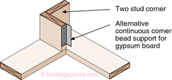
Figure 3: Two-Stud Corner – Gypsum board supported by a corner clip yielding a “floating corner” reducing drywall cracks and call backs.
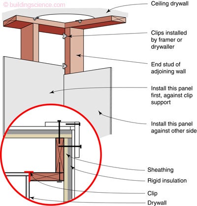
Figure 4: Trim Support – Note that the trim is installed over the wall cladding. Alternatively, a 2x4 can be added to support the wall cladding and trim; see Photograph 8.
Where interior walls intersect exterior walls we have more controversy with today’s advanced framing. I just don’t understand the issues associated with a plate connection and ladder blocking (Figure 5 and Figure 6). Actually, I do understand the issues. Anything new tends to be an issue just because it is new. Even if in this case the “new” is actually decades old.
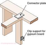
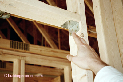
Figure 5: Intersecting Interior Wall – Metal connector plate is used to connect interior wall to exterior wall.
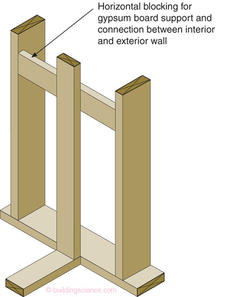
Figure 6: Ladder Blocking – Horizontal blocking used to support gypsum board and tie interior and exterior wall together.
Single top plates seem to be the biggest problem. Not from a structural perspective or from a constructability perspective but from a perception perspective. There are two ways of making a connection: with a metal plate (Figure 7) or with a wood splice (Figure 8). The approach taken is purely one based on preference by the framer. Some framers love the plate others the splice. It is another one of those Mary Ann vs. Ginger things.
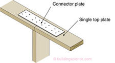
Figure 7: Top Plate Connection – Metal plate is used to connect top plates to one another.
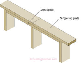
Figure 8: Top Plate Splice – Wood blocking is used as a splice to connect top plates together. Note that the “middle” stud is cut shorter to accommodate the wood splice.
One thing I can say for certain – you do not need a double top plate to straighten out the wall. Give me a break. The floor diaphragm and the roof diaphragm do this. Not an additional top plate. Most us (yes, I used to frame when I was young – in ancient times before the flood and wars…) straightened walls during framing by using something called braces.
The real change involving single top plates is that when you are framing an 8-foot wall the studs have to be 1.5 inches longer. Standard “pre-cuts” don’t work. You need 94 inchers not 92.5 inchers. Easy, take 8 footers and cut them. It takes one guy about 30 minutes with a chop saw to do all of the studs in the typical house. In fact lots of framers do this anyway, because “pre-cuts” cost more to buy than 8 footers. How weird is that.
Load bearing walls need headers and advanced framing typically involves using single headers with the header pushed to the exterior of the wall (Figure 9). This keeps the header away from the gypsum board so that boarders can’t attach to it so that shrinkage in the header does not result in a crack in the drywall.
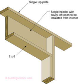
Figure 9: Single Header - Header pushed to the exterior of the wall. This keeps the header away from the gypsum board so that boarders can’t attach to it so that shrinkage in the header does not result in a crack in the drywall.
The most significant change is the fact that the walls are thicker and we have to figure out what to do with 4 inches? Do we make the foundation wider? Do we loose 4 inches to the interior? Do we keep the foundation the same, but cantilever the walls? Decisions. Decisions. These are not trivial. In production housing interior dimensions are a big deal and can mess up kitchen layouts, hallways and stairs. Site set backs as well – no kidding. It typically means that the drawings have to be redone. And that folks is the biggest knock against advanced framing. Taking existing floor plans and redrawing them is a $1,000 to $1,500 hit per plan for a production builder. Of course, this is not a problem if the plans are drawn up from scratch to be “advanced frame.”
What about floors? What about them? The floor framing is now on 24-inch centers and that means the floor sheathing has to be thicker. The savings in the floor framing covers the cost of the thicker floor sheathing. Next.
Folks, the interior walls are also framed on 24-inch centers. But these ones are 2x4’s. And almost all of them are not load bearing so the connections are pretty much non-structural (Photograph 5).
Photograph 5: Interior Wall Framing - Also framed on 24-inch centers. But these ones are 2x4’s. And almost all of them are not load bearing so the connections are pretty much non-structural.
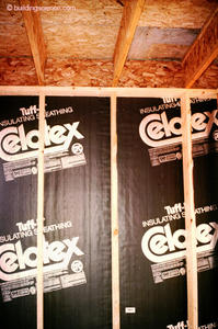
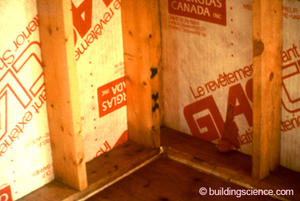
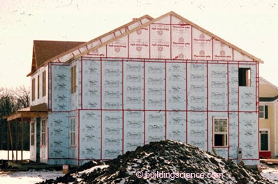
Things get interesting when we add insulating sheathing. Now insulating sheathing is not part of advanced framing. It is just that most folks that use advanced framing today also use insulating sheathing (Photograph 6). With insulating sheathing the water control layer is the exterior face of the insulating sheathing taped. Insulating sheathing provides no “racking resistance” or “shear” properties. For that we need OSB or plywood “braced wall panels” (a.k.a. “shear panels”) – and most builders build them into corners (Photograph 7). This leads to interesting corner construction (Photograph 8). The combination of advanced framing and insulating sheathing leads to deep window openings (Photograph 9). Window returns are typically gypsum board with wood trim only at the bottom.
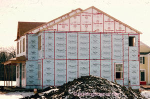
Photograph 6: Insulating Sheathing - With insulating sheathing the water control layer is the exterior face of the insulating sheathing taped.
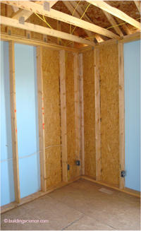
Photograph 7: OSB Braced Wall Panels - Insulating sheathing provides no “racking resistance” or “shear” properties. For that we need OSB or plywood braced wall panels – and most builders build them into corners.
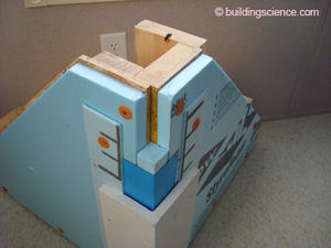
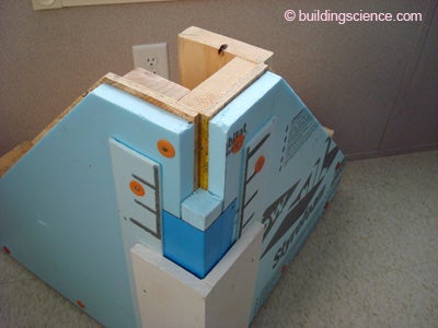
Photograph 8: Corner Framing With OSB and Insulating Sheathing – Note that the foam sheathing is reduced over the OSB shear panel so that the thickness of both sheathing layers line up with the thickness of the sheathing in the field of the wall. Also, note the spacer strip between the cladding and the exterior face of the insulating sheathing to provide back ventilation and drainage of the cladding layer and trim.
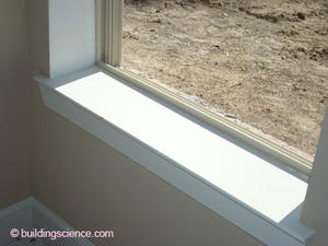
Photograph 9: Deep Window Openings - The combination of advanced framing and insulating sheathing leads to deep window openings. Window returns are typically gypsum board with wood trim only at the bottom.
So how come we don’t see lots of advanced framing? Mostly institutional inertia. Even change that saves money, saves energy, saves resources and reduces callbacks is slow to be adopted because change in general is hard. In the 1970’s there was not enough reason to change standard framing. I think we will see a different outcome this time around.
Footnotes:
The “Illinois cottage” was a site-built stick framed demonstration house displayed at the Paris Exhibition of 1867 (1) as a display of American technological prowess that revolutionized housing construction throughout the world with some help from Mrs. O’Leary’s cow and a century later with help from the NAHB. Mrs. O’Leary’s cow razed a city and the NAHB helped build a nation. After the Chicago fire the city was rebuilt with the new technology faster than the time it takes to get a building permit in Chicago today. Technology today has been supplanted by the “nomenklatura” – “nomenklatura” is the name weary Comrades’ in the old Soviet Union gave to nameless bureaucrats that killed initiative and drive and innovation (it is derived from “nomenclautura” – Latin for “list of names”). If someone invented “wood” today it would never be approved as a building material and it certainly wouldn’t be allowed to be used as a structural element in frame construction – assuming that frame construction would even be allowed. Take note ICC ES and CCMC.
(1) The Solar Decathlon held on the Mall in Washington, DC will be regarded in a century from now by subsequent generations with the same awe that we today regard the Paris Exhibition of 1867.
Chicago’s George Washington Snow and Augustine Taylor are arguably the “inventors” of modern stick framing – according to folks from Chicago. The French and some Dalhousie folks have a different view.
I love this sentence – a civilian reading it would have no clue – it is like a foreign language or like trying to understand your kid’s text messages.
The R-value of the advanced frame assembly is 13.9 and the R-value of the standard frame assembly is 7.7 using the ASHRAE Fundamentals simple parallel paths heat flow calculation procedure and fiberglass batts as the cavity insulation. For you architects this is a 75 percent improvement in thermal resistance. For everyone else, this is a big number.
This “look and feel” thing is not as irrational as it sounds at first blush. Prospective buyers walking these types of frames during construction notice the difference almost immediately and it resonates with them. Things “line up” and everything seems more “rational” because of that. The approach exudes “quality” because things do not look “random” and “random” implies “chaos” and “chaos” is not comforting to a homebuyer. Some builders have said they would use the approach even if it wasn’t faster or cheaper or more energy efficient – they would use it simply because it helps sell the house. The argument that the approach leads to a “cheaper” look because the studs are farther apart with single top plates has not gotten traction in the field walks mostly because the studs are thicker. The 2x6’s replacing the 2x4’s really do make the wall “look” stronger even though they are farther apart and they make that argument go away. The single top plate is rarely noticed and if it is noticed the single top plate versus double top plate argument is easily countered by pointing out that everything lines up so a double top plate for load transfer is unnecessary. Civilians really do “get” the load transfer argument.
HUD established an Office of Research and Technology in 1967. George Romney, Mitt’s father, was Secretary of HUD and promoted “Operation Breakthrough” (1969 to 1978). George Romney placed a strong emphasis on building technology. The early assistant secretary’s running the Office of Research and Technology had technical backgrounds, but by the end of Operation Breakthrough economists were appointed to run the show. HUD research has never recovered. Out of Operation Breakthrough came a seminal document authored by the NAHB Research Foundation and published in November, 1977: “Reducing Home Building Costs With OVE Design and Construction.” I got my hands on a copy in 1981 and had built my first “advanced frame” “OVE” house by 1982. I still get goose bumps when I read it today. Wow. Well-done NAHB. It covered everything, modular dimensioning, minimizing surface areas while maximizing floor areas, stack-framing, two-stud corners, single top plates, no headers, or single headers, it had it all.
The term “advanced framing” did not come from me. I think some of the early energy and environmental greenie weenie geeks wanted to change the name mostly to annoy the NAHB because they felt that the NAHB was not doing enough to promote energy conservation in housing – and yet here was a magnificent example of cost effective energy conservation and resource conservation – and from the NAHB no less – how dare they (the NAHB) do something really good – it does not fit the rhetorical energy geek greenie weenie template.