The design of building enclosures to control rain penetration and control rain shedding is typically based on experience and rules of thumb that make use of traditional details. Unlike heat flow, vapor diffusion, air leakage, etc. there is no theory of rain control to aid the designer or analyst of building enclosures.
Introduction
The design of building enclosures to control rain penetration and control rain shedding is typically based on experience and rules of thumb that make use of traditional details. Unlike heat flow, vapor diffusion, air leakage, etc. there is no theory of rain control to aid the designer or analyst of building enclosures.
Theoretical and empirical means of predicting the amount of driving rain deposited on a vertical above-grade building enclosure have been partially developed elsewhere (Straube, 1998). The objective of this digest is to present the development of a rational and rigorous means of describing, understanding, and classifying rain control for the above-grade enclosure. Such a description and classification are needed because this will:
aid designers in understanding the function of each material and layer in an assembly. Such understanding will result in better enclosure designs that more reliably and economically meet a project's performance requirements;
allow water penetration tests to be developed and applied that impose realistic loads and that more closely match likely service conditions. The results of such testing can also be more accurately interpreted to aid the prediction of actual performance under extreme and typical weather conditions; and
provide a means for the accurate assessment of the reasons for enclosure failures and therefore enhance proper repair and retrofit strategies.
The discussion initially focuses on what happens to rainwater deposited on an external wall surface.
Drainage, Storage, And Transmission
Rain deposited on a wall can either be:
drained (the terms shed or surface drainage are often used in the context of the exterior surface of a wall),
stored (absorbed by capillarity or attached by surface tension), or
transmitted further into the wall (rain penetration or infiltration are other common terms).
At the exterior surface of a wall, some, even most, of the water deposited and draining on the surface of a wall can be removed from the surface by features such as drips and ledges. If the wall consists of many layers, each of them responds in a manner similar to that described above. If water penetrates through an entire wall assembly, that assembly has obviously failed to control rain penetration. However, partial water penetration into the enclosure may also be considered as failure since transmission of rain water into any sensitive layer of a wall assembly may cause damage, degrade performance, and affect durability. Although all water theoretically causes wetting of the material, in a practical sense only the water that is stored for longer than a few minutes will be considered to have caused wetting, i.e., this water must be subsequently removed.
The above reasoning can be made more rigorous by applying simple mathematical rules. Consider the enclosure assembly element shown in Figure 1. This n-layer wall system can be discretised into smaller sub-elements, each chosen to be sufficiently small so that the drainage, storage and transmission characteristics are constant over the element.
Figure 1: Discretisation of enclosure into sub-elements and layers
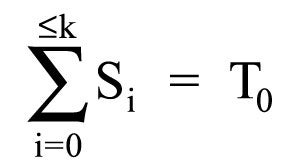
At each layer i, the water from the previous layer, i-1, must be either stored (Si), drained (Di) or transmitted to the next layer (Ti) (Figure 2). Since the sub-element under consideration is one-dimensional, drainage is considered as water that leaves the assembly. In a 2-D (height and layers) or 3-D (height, width, layers) analysis, drainage (Di,x,y) may subsequently become stored (Si,x,y) or transmitted water (Ti,x,y) in an adjoining sub-element.
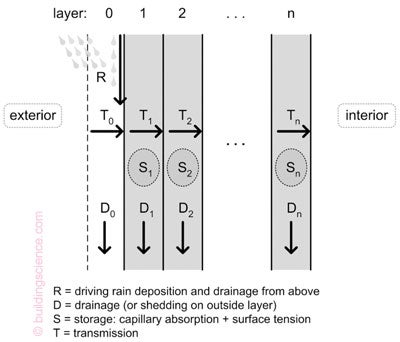
Figure 2: Distribution of rain within a multi-layer enclosure assembly
From observation of Figure 2 and conservation of mass:
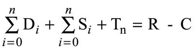 (Eq. 1)
for any given period of time, ranging from a few seconds to an entire rain event. This constant relationship will henceforth be termed the DST ratio for brevity. R is the amount of surface water from both rain deposition and drainage from above. C is the amount of water that splashes back or is removed from the surface by features such as drips, ledges, etc.
The interfaces between enclosure layers can have an important influence on an assembly's storage, drainage and transmission characteristics. Water does not drain in a layer such as an air gap, but rather water flows along a surface, e.g., the interface between the back of the cladding and the airspace or the interface between roofing paper and a roof shingle. The use and definition of layers and interfaces in the model depends on the need and on the analyst’s modelling preferences. In practise, clear air-filled gaps over about ¼” (6 mm) can easily allow drainage on both surfaces of the gap. If the gap is much less than about 1/8” (3 mm), water draining in a gap tends to contacts both surfaces and hence can be considered as a single layer.
It is also useful to define an imaginary outer surface layer, layer zero. This imaginary layer, analogous to a surface film in heat transfer theory, allows one to consider surface drainage as this layer's drainage (D0), water beading on the surface as storage (S0), and transmission (T0) as the water that penetrates the outer surface of the cladding:
Note that S0 is a negligible quantity for walls, although it can be significant for low-slope and flat roofs. By contrast, C is usually zero for roofs (rain drops may splash back from the surface on impact, but eventually end up on the roof), but can be quite significant for walls. (Recall that cast off water, C, includes water that breaks free of the surface because of drops shattering on impact, surface projections, flashings, etc.)
For walls, S0 can be assumed to be small and Equation 2 rewritten as:
Equation 3 merely states the obvious fact that rainwater deposited on a wall can either penetrate (T0) or be drained (D0). The amount of water stored on the exterior surface of an enclosure has been studied, and depends strongly on the texture and contact angle. However, values of 50 to 200 g/m2 are typical: this water very quickly evaporates after rain deposition ceases.
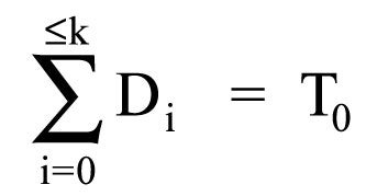
Since the total amount of rainwater that reaches an interior enclosure layer (Ti-1) acts as if rain were being deposited on that layer, then for any given layer:
Di + Si + Ti = Ti-1 for all layers i = 1 to n (Eq. 4)
It is useful to generalise values for each layer by providing fractions of rainwater. Since Di + Si + Ti =Ti-1 , then
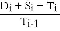 = 1.0 or, (Eq. 5)
di + si + ti = 1.0 (Eq. 6)
where lower case letters denote rainwater fractions, e.g. di = Di / Ti-1
The design strategy in most wall assemblies is such that water cannot penetrate further than a specific surface (layer), k, k ≤ n , or it will be considered to have failed to control rainwater. It is logical to choose a layer k that can tolerate wetting, and is able to dry. Most would not accept rainwater penetrating as far as a layer made of fibreglass batt insulation, or paper faced gypsum. However, in practise, a small amount of water may penetrate beyond a drainage plane to a material with a moderate amount of safe storage capacity (for example, plywood). An analyst may define this as failure, although no failure actually occurs in service. Hence, the definition of k may be less than clear in some designs and depends on rain loading, risk tolerance, and drying capacity. From a design point of view, one can usually choose a layer beyond which rainwater should not penetrate, e.g., into the studspace of a framed wall, or onto the interior drywall finish of a concrete masonry wall). In the case of k=n, every layer of the assembly is presumed to be tolerant to rain wetting.
The description given above is valid for time scales of perhaps a few minutes. Because drainage is not instantaneous and rain intensity varies, mass may be not be conserved for very short time scales (e.g., less than a minute) since water may accumulate in a film before draining from the sub-element.
However, in longer time scales the relative fractions will change: capillary theory requires that as the amount stored in a layer increases, the rate of storage (i.e., absorption) will decrease and as the intensity of deposition increases, the ability of materials to absorb water will decrease. An extreme example is highly absorbent cladding during low intensity rain events: rainwater deposited on the surface of such cladding will first be absorbed, perhaps for some time. Eventually, the surface will reach a certain moisture content at which water deposition will exceed the water uptake capacity of the material and both surface drainage and transmission will begin.
The above analysis of rainwater movement leads to some conclusions:
the relative amount of water dealt with by each part of the DST ratio, and at which surfaces/layers is a rational and rigorous, non-subjective means of describing the behavior of building enclosure elements exposed to rain;
because the response of materials and interfaces changes due to changes in moisture content, temperature, time, etc., enclosure response is a function of the same variables;
based on the previous conclusions, the rate and duration of rain deposition, the time between rain events, and the drying of the envelope, i.e., the environmental conditions preceding the time in question, may all influence the behavior of an enclosure to a driving rain event.
These conclusions have significance for understanding in-service performance and interpreting the results of rain penetration testing, both in the lab and the field.
Rain Control Strategies
Three design strategies are used to control rain penetration through building enclosures. It has been shown above that the behavior of an enclosure system may change with time, rainfall intensity, temperature, etc. However, a designer must chose a strategy so that s/he can design and specify a system, and typically this means the system must be designed for the worst likely rain scenario. In some cases this “worst case” is an intense short-duration rainstorm. In other cases, the worst case may be a series of long-duration moderately intense storms.
The design options that are available to designers are discussed in the context of the relative fractions of rainwater dealt with by each mechanism at each wall layer. Regardless of the control strategy, the amount of water drained from the surface is D0 and the amount that penetrates the outer surface of the envelope is T0. Bear in mind that R denotes the volume of rainwater deposited on the surface and/or drained from above and C the amount of previously deposited water removed.
Face-Sealed (Barrier Wall) / Perfect Barrier System
A multi-layer enclosure assembly may contain a single layer where the amount of rainwater transmitted inward must be zero, i.e., at one layer, j:
Tj = tj = 0, j ≤ k, (Eq. 7)
The general term "perfect barrier" system (or “barrier wall”) is preferred.1 If the perfect barrier is located at the exterior-most face of the wall, the rain control strategy is termed "face-sealed." Although the perfectly watertight layer j is often located on the exterior face of an assembly, e.g., for a face-sealed EIFS cladding, j=1 and t1=0, it need not be so. If the perfect barrier is located within the assembly the term “concealed barrier” (and occasionally “protected membrane”) has been coined. Concealed barriers have the advantage that they are exposed to less UV radiation, fewer aesthetic restrictions in material choice, small temperature variations, and less moisture loading.
Since the transmission characteristics of most perfect barrier layers (such as asphaltic and polymeric membranes) is almost always moisture content independent in practical systems, the rain control performance of a perfect barrier system is independent of previous weather conditions. However, in the case of a building paper concealed barrier behind stucco, the perforations by fasteners, and the moisture sensitive nature of the material, means failures can often occur under prolonged and high exposure to rain.
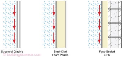
Figure 3: Perfect Barrier Walls
Concealed or protected barrier systems (i.e., perfect barriers with j greater than 1) must also provide drainage or storage for layers n j. For example, although inverted roofs are classed as perfect barrier systems, they must still provide drainage. They do not rely on drainage for good rain control, merely to reduce structural loads and enhance their durability and fault tolerance.

Figure 4: Metal-cladding is being placed over a concealed barrier (a waterproof fully-adhered “self-sealing” membrane) to form the rain control system of this sloped roof.
In the special but common case of a face-sealed perfect barrier, j = 1, and the following characteristics apply:
T1 = t1 = 0 (Eq. 8)
and so,
D0 = R - C (Eq. 9)
i.e., all driving rain deposition and surface drainage from above must be drained on the surface. Drainage and storage within the assembly therefore do not play a role in providing rain control in functional face-sealed perfect barrier systems.
Storage or Mass System
The oldest rain control strategy is to provide an assembly with enough storage mass to absorb all rainwater that is not drained or otherwise removed from the outer surface. By draining or absorbing all rainwater, such an assembly can prevent inward transmission, i.e.,
 (Eq. 10)
Although enclosures employing this strategy might be termed "moisture storage", or “reservoir” systems, "mass" is often used because a large quantity of material is usually required to provide sufficient storage. Unlike perfect barrier or drained systems the maximum quantity of rain that can be controlled is limited by the storage capacity available. Therefore, the performance of mass systems is highly dependent on weather conditions, e.g. if a series of rain events occurs and drying conditions are poor, the storage capacity may be exceeded and failure to control rain will result. Also, unlike perfect barrier or screened drained systems (see next), mass systems do not need to use drainage within the assembly.
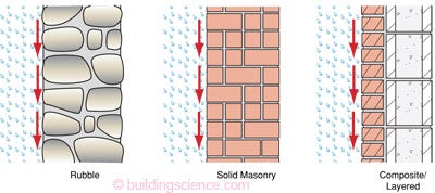
Figure 5: Storage Wall Systems
The storage capacity of the system is not the only characteristic in such a system that is important in rain control. The water transmission of the various layers and interfaces can play a critical role. For example, consider a 400-mm thick, solid brick masonry wall with a certain amount of storage capacity. By applying a thin 15-mm thick, polymer-modified cement rendering, the storage capacity is only marginally increased, but the liquid water transmission of this outer layer is so low, even if cracked or otherwise imperfect, that the rain penetration control of the system is vastly improved.

Figure 6: This old enclosure controls rain penetration by storing moisture in many layers of masonry. Note that overhang and window details shed rain off the surface, thereby reducing the amount of rainwater that needs to be stored between wetting events.
Hence, any treatment that reduces surface water absorption while not reducing the water storage capacity of a wall will increase the ability for the assembly to control rain. However, if water is not absorbed at the surface it will increase the frequency and duration of a film of flowing water on the surface of the enclosure. This in turn will increase the importance of controlling surface drainage and also increase the likelihood of rain penetration through flaws, cracks, and other openings, intentional or not, in the enclosure.
The drying potential of a mass wall relative to the frequency and quantity of rain deposition is also important. Hence, when historic masonry buildings are retrofit, care must be taken not to decrease the drying capacity without an associated decrease in wetting or rain control may suddenly cease to be acceptable (see also BSD-114: Interior Insulation Retrofits of Load-Bearing Masonry Walls In Cold Climates).
Therefore, the rain control of mass systems will be dependent on the moisture storage provided relative to the liquid water transmission through the exterior surface and the drying potential of the wall in its microclimatic exposure.
Drained Systems
Another approach to controlling rainwater is to accept that some water will penetrate the outer surface (the cladding “screens” rain) and remove this water by designing an assembly that provides drainage. This approach is labelled the “drained” or “drained-screened” approach. Drainage is required for proper function but need not be provided at one layer only. In fact, if drainage were required to be provided at one layer only, the wall would be acting as a perfect barrier system, since an enclosure in which Dj = T0 and tj = 0 for any layer j, is the definition of a perfect barrier. Screened and drained walls control rain penetration by reducing the amount of water transmitted at each of several layers, i.e.:
 (Eq. 11)
Although the dominant control mechanism is drainage, the layered and screening nature of the assembly is also important in this approach. The defining characteristics of a screened-drained wall system are that the drainage need not be complete at any one layer, transmission need not be completely controlled at any given layer, and storage is not required. The lack of required perfection at any layer is one of the most important features that has lead to the rapid acceptance of drained systems in modern enclosure design.
Because drained enclosure systems control rain penetration by reducing the successive fractions of water that are transmitted inward, the following relation can be defined: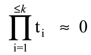 (Eq. 12)
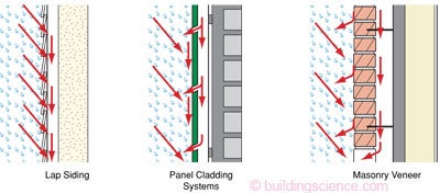
Figure 7: Drained Wall Systems
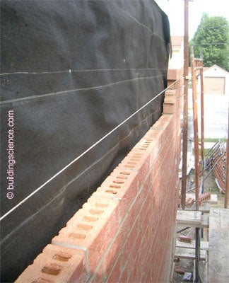
Figure 8: Drained brick veneer, employing lapped building paper as the drainage plane
The practical implications of Equation 12 can be better understood by considering an example assembly with three layers, each with a small penetration fraction, say 10%. The amount of rain penetrating the third layer would be only 0.1·0.1·0.1·(T0) = 0.001·(T0). If all rain deposited on the envelope were to penetrate the screen (T0 = R - C), the amount of water penetrating the third layer during a typical heavy rain storm (e.g., 10 l/m2/hr) would be 0.1% of 10 l/m2/hr, or 10 ml/m2/hr, the equivalent of a water film 0.01 mm thick! Therefore, providing even a small amount of storage in the third layer of this wall will ensure that rain penetration is controlled. In fact, failure to control rainwater in such walls is usually the result of a failure to drain since the required amount of drainage in this wall equals 0.999·(T1). This line of reasoning supports the "drained" part of the label applied to this type of system.
The term “rainscreen” has been rather loosely applied by practitioners and researchers to several special cases of drained walls, especially those that use several layers and several mechanisms to control rain. A rainscreen system typically contains a drainage layer as the second layer of the assembly, (i.e. d2 ≈ 1.0). The first layer (j=1) is the screen, and the second layer (j=2) is often the backside of the screen. Almost without exception, functional rain screen walls provide several additional drainage layers, for example, the front and back of the sheathing paper. Modern windows, car doors, and two-stage joints are exceptions, in that they typically have precisely two layers (hence the term two stage weather tightening). Although these types of joints provide an “almost” perfect inner layer, the intent of the outer layer is to significantly reduce the potential for any water on the second layer.
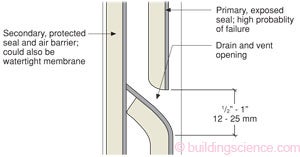
Figure 9: A vertical section through a two-stage joint
It must be noted that the outer layer of a multi-layer drained wall is much more than a rain screen; it must also resist wind, snow, solar radiation, impact, etc.
A pressure-equalised rain screen is a very special type of screened and drained system that equalises (or moderates) air pressure differences acting on the screen to reduce the transmission fraction of the screen. Since all field measurements of pressures behind screens have shown that the pressure is rarely equalised, pressure-moderated rain screen would be a more accurate label for most practical systems. Some types of two-stage joints may also be pressure-moderated and should be labelled pressure moderated two stage joints.
Behavior of the Actual Envelope
During most rain events, many envelope systems may actually perform quite differently than designed. For example, if drainage, storage or both are provided in an enclosure element designed and built as a perfect barrier system, the perfect barrier need not be perfect.
Exterior Insulation and Finish Systems (EIFS) are one of the most popular and contentious face-sealed perfect barrier wall systems. The existence of cracked lamina, leaky windows, and failed sealants in EIFS has been widely documented. For example, in a recent survey of 50 EIFS-clad buildings, Kenney and Piper (1995) found 91% of the buildings over 9 years old to have lamina cracks large enough for water penetration. There are, however, millions of square feet of EIFS in North America that continue to satisfactorily control rain. This is not necessarily because the lamina (the plane assumed by designers to be perfectly watertight) allows no transmission, but may be because the insulation and/or substrate has sufficient storage to store the very small fraction t1, that penetrates. In other cases, this storage capacity may act in conjunction with drainage that is inadvertently provided by interface layers and large pored or fibrous insulation materials.
In most reported cases, EIFS fail to control rain because of poor detailing of joints between elements and penetrations, and poor quality windows. Joints are often made with poor workmanship and poor quality field-applied sealant that breaks down quickly when exposed to the sun. The failure of face-sealed sealant joints is the location of failure rather than the lamina. There is insufficient safe storage capacity behind the lamina to deal with the excessive amounts of water that penetrate because of such conditions and the result is failure of the assembly. The inability of poorly-built EIFS systems to dry once rain penetrates, an important part of a moisture storage rain control strategy, often results in other serious performance and durability problems (for example, the well-publicised cases in Wilmington, North Carolina).
As noted earlier, a "rain screen" drained system typically contains a drainage layer as the second layer of the assembly, (i.e. D2 » 1.0). In the popular brick veneer rain screen wall system, drainage is provided along both the inside face of the veneer, layer 2, and the outside face of the inner wythe, layer 4. The airspace acts as a capillary break so that the fraction crossing it is as small as possible, t3 » 0. If drainage is provided, usually in the form of an unobstructed air space, such a wall system will control rain independently of moisture content. The critical characteristic of a drained wall system is that the drainage need not be perfect at any one layer, nor does transmission need to be completely controlled. Several "almost perfect" layers, each with the ability to drain, act in conjunction to control rainwater.
Storage may play an important role in walls designed as drained-screened wall systems. For example, in most masonry veneers, S1 = R-C during many rain events (which typically have rain deposition rates less than the masonry absorption rates: see Straube, 1998) and therefore no water is available to be shed or transmitted inward. However, during extended rainy periods and intense rain events, the veneer may become saturated, and some water will penetrate the permeable veneer (since masonry veneers are remarkably water permeable). The layers behind the veneer only need to perform their drainage function during extreme events, and it is therefore only during these events that drainage becomes critical. Inspection of many functional veneer walls shows that drainage spaces are often blocked by mortar bridges and dams. The exposure conditions and storage capacity of such walls suggest that they are actually behaving as mass walls, with several low transmittance layers (e.g., the sheathing membrane/WRB) behind the storage. While these walls may be functional in certain exposure conditions (e.g., low-rise housing) this may not be the case if they are used in an area with different climate. If the same wall were exposed to more driving rain deposition (e.g., near the top of high rise buildings), or less drying potential (e.g., Maine, Vancouver or other rainy, coastal climates), the storage capacity could be exceeded resulting in a rain control failure.
Brick veneer wall systems, like most screened-drained enclosure systems, should be analysed as two- or three-dimensional systems. Although the majority of a brick veneer assembly may be drained and screened, the most critical component is usually the flashing at the base of the drainage cavity. The flashing is usually designed as a perfect barrier exposed to small hydraulic head — any penetration, crack, or unsealed lap joint can lead to a rain control failure. However, one of the benefits of a concealed barrier system is that the barrier layer, the flashing in this example, is protected from direct weather exposure.
Roof Systems
Low-slope roof assemblies provide many examples of the perfect barrier approach. An inverted roof is one which has a waterproof membrane (t = 0) located below several layers of moisture tolerant materials such as crushed stone (i=1), a geotextile (i=2), and extruded polystyrene insulation (i=3). In this assembly, T4 = 0, and usually k=4. It is an accepted fact that a large fraction of water is drained along the top of the insulation (typically, d2 ≅ 70%) in these systems. Nevertheless, the success of these designs rests on the perfection of the protected membrane layer.
Most low-slope roofs are still designed with exposed membranes, i.e., face-sealed, perfect barrier systems. Because of the often shorter-than-desired life-span of these roofs, a new philosophy has recently arisen (Desjarlais, 1995). This philosophy accepts the fact that the exposed membrane will not be perfect for the design life of the roof. Numerous layers of storage are provided, typically in the form of insulating fibreboard, which are sized to allow for the safe storage of moisture equal to T1. Solar heating and appropriately vapor permeable inner layers assist in removing this water by evaporation and diffusion to the interior. This type of roof therefore is intended, by design, to revert to a mass system near its end of life, with a very low transmittance outer layer and enhanced drying potential to the interior (ensured by not providing an interior polyethylene vapor barrier).
Sloped shingled roofs are drained-screened systems with the unique characteristic that the majority of drainage occurs on the surface. The overlapping shingles however, provide a second drainage layer. If the roof deck is covered with a water resistant roofing paper, as is often the case, this provides a third layer of drainage. In all cases, the roof sheathing acts as a final drainage plane and a storage layer. It is clear from the theory presented here that increasing the number of layers in a drained-screened enclosure system will provide more protection against higher rain loads. Asphalt shingle roofs provide a practical example of this theory. For lower-slope shingle applications (for slopes between 1:12 and 3:12) shingle manufacturers generally recommend doubling the layers of shingles, i.e., providing a total of 4 drainage layers.
In summary, it can be concluded that the rain control of a perfect barrier enclosure is dependent on a single layer resisting all inward water transmission, a mass or storage system relies on sufficient storage capacity, and a drained-screened system depends on drainage at other than the outside surface. As has been pointed out above, despite the fraction that dominates, all fractions play a role in almost all wall systems. If some storage and drainage is possible in walls designed as perfect barriers, these walls may not fail even if and when the perfect barrier is less than perfect. In the same way, many screened and drained walls may, in fact, have poor drainage and therefore can only function if sufficient storage is available. However, the designer is often concerned with the behavior of the wall under extreme events, and should choose a rain control strategy from one of the three.
Wall Classification
An enclosure wall classification system based on the above analysis is presented in Figure 10. This system, developed over the last several years (Straube 1993, Straube and Burnett, 1997), is based on the method by which the wall system controls rain penetration. Because the control of rainwater penetration has historically been a major function of above-grade enclosure walls, the classification is widely useful. The classification is independent of materials, building function, or design intent. Although the focus of this classification is on wall systems, it can be extended to the other above-grade building enclosure systems, especially windows and roofs.
A fundamentally important point is that walls should be considered to be comprised of elements and the joints between these elements. Both the elements and joints may be classified in the same manner, but the classification of the joints in any given system may be quite different than for the element. This distinction is critical for some systems; perfect barrier elements made of modern materials rarely fail (often because they are built of high performance materials under tight quality control in factories), but the joints between the elements are a common source of problems, e.g., joints between metal or precast concrete panels, window openings in EIFS, laps of flashing, etc. Windows are commonly designed assuming that the glazing unit is a perfect barrier and that the joints must be drained.
The primary and initial classification of this system is whether a wall is a perfect barrier or an imperfect barrier.
Perfect barriers stop all water penetration at a single plane, as much as a perfect air barrier would prevent airflow. Examples of perfect barrier walls are some window frames, EIFS, and metal and glass curtain wall systems. Because it is very difficult to build and maintain a perfect barrier wall, most walls are designed as, or perform as, imperfect barrier wall systems of either the mass type or the screened type.
Mass or storage systems control rain penetration by absorbing and storing rainwater which penetrates the exterior surface. In a functional mass wall this moisture is eventually removed by evaporative drying before it reaches the inner surface of the wall. Some examples of mass walls include adobe, solid brick masonry, and single-wythe block masonry. Poorly drained masonry cavity walls (i.e., those with blocked air spaces or blocked weep holes) often behave as multi-layer mass walls.
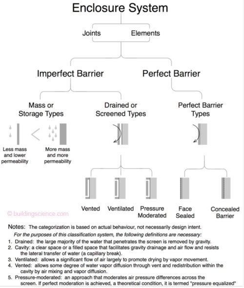
Figure 10: Wall classification with regard to rain penetration control
Screened and drained walls control rain penetration by draining any water that is not shed from the front face. Such walls are also imperfect-barrier type wall systems in that this approach acknowledges that some rainwater will penetrate the outer surface. A supplementary mechanism, such as a capillary break, storage, and multiple drainage planes are usually employed to resist further inward movement of the water that penetrates the screen. The dashed lines in the figure indicate that, while not desirable, poorly drained walls do exist. Some examples of drained wall systems include cavity walls, brick and stone veneer, vinyl siding, two-stage joints, and drained EIFS.
Although the above is all that is necessary to classify a design, the multiple and important roles of air spaces and cavities means that further practical classifications are possible.
Function of a Cavity
A cavity behind the screen provides a capillary break, as well as a clear path for gravity drainage and a path for airflow. A cavity is defined for our purposes as any continuous space behind the screen, which may be filled with a porous material, that fulfills these functions. An air space is the unfilled part of the cavity.2 (Note: from a structural point of view, a cavity is the space between two wythes. It may be empty, completely filled, or partially filled by insulation).
A small gap is all that is needed to provide drainage. This gap may be 1/16” or less. Hence a drained wall need not have a large gap, or cavity, and in fact increasing the gap width does almost nothing to improve drainage.
However, a larger cavity can provide for air movement and enhanced moisture re-distribution, as well as dimensional tolerances necessary for many claddings (such as masonry). Given a cavity behind the screen, four major sub-classifications relating to air movement and vents are possible: vented, pressure-moderated, ventilated, or pressure moderated and drained.
A vented wall system allows some degree of water vapor diffusion and air mixing between the cavity and the exterior. Venting (and, to a greater degree, ventilation) provides a mechanism for the removal of water that does not drain from behind the cladding. Venting, or better still, ventilation, may also remove water vapor that may have diffused outward from the inner wythe. Venting may be explicitly provided (e.g., in the form of unfilled head joints in brick veneers) or it may be provided implicitly by the nature of the cladding (e.g., in the form of openings and cracks in overlapping wood siding).
By increasing the flow of air into and through the cavity, a relatively large volume of water vapor can be transported from the cavity. Such a ventilated wall will assist the drying of both the inner wythe and the cladding by providing a mechanism for the removal of water that does not drain from behind the cladding. Ventilation may also remove water vapor that may have diffused outward from the inner wythe. The distinction between vented and ventilated walls is not clear — it is presumed here that ventilated walls are those that have a “significant” amount of airflow. The relative significance of various flow volumes will be discussed elsewhere..
A pressure-moderated wall system promotes the moderation of the pressure difference across the cladding. The proper choice of venting, i.e., size, number, and location, and the division of the cavity into stiff, airtight compartments are necessary requirements. Although such walls have heretofore been described as pressure equalized rainscreens (PER) in Canada, instantaneous pressure equalization rarely occurs in reality, and the screen deals with more than rain. Hence the more realistic term, pressure-moderated screened or pressure-moderated drained wall, is preferred.
A drained and ventilated wall is not only feasible, it should be the preferred solution for most applications where high performance is required.
Conclusions
The rain control classification described provides a rigorous and practical means of understanding the function of each layer and material in an assembly. This approach will aid the development of realistic test methods and provide the means for a more accurate assessment of the reasons for enclosure failures and therefore the proper repair and retrofit strategies.
References
Kenney, R.J. and Piper, R.S., 1995. “Proposed Material and Application Standards for More Durable Exterior Insulation and Finish Systems”, Development, Use, and Performance of Exterior Insulation and Finish Systems, ASTM STP 1187, Mark Williams and Richard Lampo, Eds., American Society of Testing and Materials, Philadelphia, pp 56-73.
Desjarlais, A.O., 1995. “Self-Drying Roofs: What!? No Dripping!”, Proceedings of Thermal Performance of the Exterior Envelopes of Buildings VI, Clearwater Beach, Florida, Dec. 2-5, pp. 763-773.
Straube, J.F., 1993. The Performance of Wall Systems Screened with Brick Veneer. M.A.Sc. Thesis, Civil Eng. Dept., University of Waterloo.
Straube, J.F., 1998. Moisture Control and Enclosure Wall System. Ph.D. Thesis, Civil Eng. Dept., University of Waterloo.
Straube, J.F., and Burnett, E.F.P., “Rain Control and Screened Wall Systems”, Proceedings of the Seventh Conference on Building Science and Technology, Toronto, Mar. 20-21, 1997, pp.17-37.
Footnotes
It may seem that “perfect barrier” is a redundant term, but the building industry almost always uses the term barrier in a relative, not absolute sense (e.g.. vapor barrier, moisture barrier). Therefore it is deemed necessary to qualify the barrier as being perfect.
From a structural point of view, a cavity is the space between two masonry wythes or between cladding and framing. It may be empty, completely filled or partially filled by insulation. From a moisture control standpoint it is the functions previously listed that are important.