Sometimes we make easy things hard. And sometimes we make hard things easy. With continuous insulation and punched openings both things are true.
The physics is easy. A wall has to control water, air, vapor and heat. A window has to control water, air, vapor and heat. Both have a water control layer, an air control layer, a vapor control layer and a thermal control layer. All you have to do is connect the water control layers to each other, the air control layers to each other, the vapor control layers to each other and the thermal control layers to each other. Oh, yeah, one other point, you don’t want the windows to be sucked out of the wall when it is really blowing.
Now it gets interesting. Where is the wall water control layer? With continuous insulation it can be the continuous insulation layer itself—or it can be behind it. It is pretty dumb to put a separate water control layer—specifically a film or thin membrane—over the exterior of the continuous insulation layer because it is impossible to install the additional layer in a practical manner—one that prevents it from getting sucked off and one that has constructible details.1
Now, I don’t have a problem with water control layer films when they are used correctly. Historically, they have an awesome track record. Tar paper, impregnated felt, coated paper, and polyolefin films go back a long way. The best performance from a wind load perspective and a durability perspective—comes from installing such films behind the continuous insulation layer over structural sheathing. That way the film is supported on both sides—it is sandwiched typically between OSB/plywood/gypsum structural sheathing on one side and the continuous insulation layer on the other. Neither sucking nor blowing cause it to flex. Of course, you can turn the structural sheathing itself into a water control layer and air control layer and not need the film layer at all.2
I think the winning technologies are to make the structural sheathing itself the water and air control layer—and to install continuous insulation over the structural sheathing (Figure 1). Back in the day we called this the “perfect wall” (see BSI-001: The Perfect Wall). Or make the continuous insulation itself the water and air control layer and include or exclude the structural sheathing based on—wait for it—structural considerations (Figure 2). Note that this is an “opinion” so everyone relax. You get to have your own opinions, too.

Figure 1: Structural Sheathing as the Water and Air Control Layer–Continuous insulation is installed over the structural sheathing.

Figure 2: Continuous Insulation as the Water and Air Control Layer–Include or exclude the structural sheathing based on structural considerations.
So, according to me, there are two locations for the water and air control layer–behind the continuous insulation or the exterior face of the continuous insulation. Now for the “pain” part–the windows. Are they going to be “innies” or “outies”? Who talks like this? Welcome to my world.
Are the windows going to be “inset” or are they going to be outboard of the structure at the exterior face of the continuous insulation? If the windows are “inset” and the water and air control layer is behind the continuous insulation everything is real easy—things “line up.” If the windows are “outset”3 and the water and control layer is the face of the continuous insulation things are also real easy—things also “line up.” But if the windows are outset and the water and control layer is behind the continuous insulation things get more complicated.
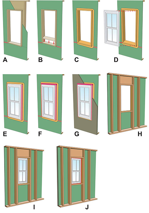
Let’s go with the easy stuff first. “Innies” with the water and air control layer being the sheathing behind the continuous insulation. Check out the sequence of installation (Figure 3). Note that the water control of the flanged window lines up with the water control of the sheathing. Note the sloping sill. Note that the pan flashing can be liquid applied or a formable membrane. Note that sealant is not necessary (or desirable) behind the window flanges. For an explanation see “BSI-067: Stuck on You”. Note that the seams in the continuous insulation do not need to be sealed or taped.
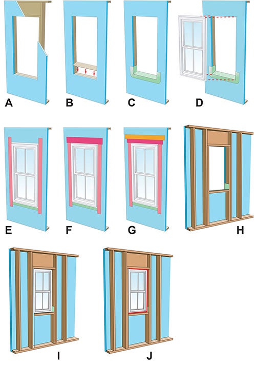
Figure 3: Window Installation Sequence For “Innies”– The water and air control layer is the sheathing behind the continuous insulation. Note that the water control of the flanged window lines up with the water control of the sheathing. Note the sloping sill. Note that the pan flashing can be liquid-applied or a formable membrane. Note that sealant is not necessary (or desirable) behind the window flanges. Note that the seams in the continuous insulation do not need to be sealed or taped.

A. Structural sheathing installed over frame wall
B. Install beveled wood siding in frame opening at sill to create slope
C. Install formable flashing at sill
D. Install window plumb, level and square
E. Install flashing tape at jambs
F. Install flashing tape at head
G. Install continuous insulation
H. Interior view prior to window installation
I. Interior view after window installation
J. Air seal window around entire perimeter with sealant and sealant back rod
And here’s a real neat point—the continuous insulation does not have to be rigid with this approach—windows being “innies” with the water control layer and air control layer being the structural sheathing. The continuous insulation does not have to be extruded polystyrene (XPS) or expanded polystyrene (EPS) or foil-faced isocyanurate. It could be mineral fiber insulation boards (a.k.a. “stone wool”). See Figure 4. It can be any type of continuous insulation: rigid or mineral fiber.

Figure 4: Mineral Fiber Insulation (“Stone Wool”)–With mineral fiber insulation the face of the mineral fiber insulation cannot be the water and air control layer. We also need structural sheathing with mineral fiber insulation. Typically the structural sheathing is turned into the water and air control layer.
And you can make the continuous insulation pretty much any thickness. Check out Photo 1. The trim is returned to the flange or face of the inset window. The flashing at the top of the window opening at the horizontal strip of head trim just covers the top of the trim itself—it only protects the top of the trim—it does not have to extend to the back of the continuous insulation and connect to the face of the structural sheathing/water control and air control layer. The window head—the flange at the top of the window—is already flashed to the face of the structural sheathing/water control and air control layer behind the continuous insulation. A gap is left at the inboard side of the horizontal return trim at the top of the window opening to let any penetrating rainwater run out between the window flange and the horizontal trim (Figure 5).
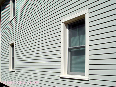
Photograph 1: Beautiful “Innies”– The trim is returned to the flange or face of the inset window. The flashing at the top of the window opening at the horizontal strip of head trim just covers the top of the trim itself–it only protects the top of the trim - it does not have to extend to the back of the continuous insulation and connect to the face of the structural sheathing/water control and air control layer.
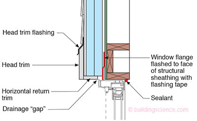
Figure 5: Window Head–The window head–the flange at the top of the window–is flashed to the face of the structural sheathing/water control and air control layer behind the continuous insulation. A gap is left at the inboard side of the horizontal return trim at the top of the window opening to let any penetrating rainwater run out between the window flange and the horizontal trim.
Now lets go with “outies” with the water and air control layer being the face of the continuous insulation. Check out the sequence of installation (Figure 6). We have seen this before. We have been doing this for over 50 years. Note that the water control of the flanged window lines up with the water control of the face of the continuous insulation. Again, note the sloping sill and that the pan flashing can be liquid applied or a formable membrane. Again, note that sealant is not necessary behind the window flanges. And finally note that there is no wood behind the window flange—you don’t need any—the flange is seated directly over the continuous insulation—you attach the window through the flange and continuous insulation to the framing with long screws.
Figure 6: Window Installation Sequence For “Outies” – The water and air control layer is the face of the continuous insulation. Note that the water control of the flanged window lines up with the water control of the face of the continuous insulation. Again note the sloping sill and that the pan flashing can be liquid applied or a formable membrane. Again note that sealant is not necessary behind the window flanges. And finally note that there is no wood behind the window flange–you don’t need any–the flange is seated directly over the continuous insulation–you attach the window through the flange and continuous insulation to the framing with long screws.
A. Insulating sheathing installed over frame wall
B. Install beveled wood siding in frame wall opening at sill to create slope
C. Install formable flashing at sill
D. Install window plumb, level and square
E. Install flashing tape at jambs
F. Install flashing tape at head
G. Install sheathing tape over flashing tape at head to terminate flashing tape
H. Interior view prior to window installation
I. Interior view after window installation
J. Air seal window around entire perimeter on interior with sealant and sealant backer rod
But we have some important changes from the “innies” approach described previously. The continuous insulation has to be rigid with this approach. It cannot be mineral fiber insulation boards (stone wool). We will deal with mineral fiber insulation boards (stone wool) later. The continuous insulation in this approach is limited to extruded polystyrene (XPS) or expanded polystyrene (EPS) or foil-faced isocyanurate. And, the seams in the continuous insulation do need to be sealed or taped. And, pay attention here, the thickness of the continuous insulation is limited to 11/2-inches. If you want to go thicker, the opening needs to be lined with a structural box (Photo 2) and the windows attached with straps (Photo 3 and Figure 7). The structural box is typically plywood or OSB and it protrudes past the exterior face of the framing the thickness of the continuous insulation. How thick can you go with the continuous insulation with the structural box? Typically 4-to-6 inches. Note that with the structural box the water control layer is wrapped into the box opening and the material is typically flashing tape.

Photograph 2: Structural Box–Typically plywood or OSB protruding past the exterior face of the framing extending the thickness of the continuous insulation. How thick can you go with the continuous insulation with the structural box? Typically 4 to 6 inches.
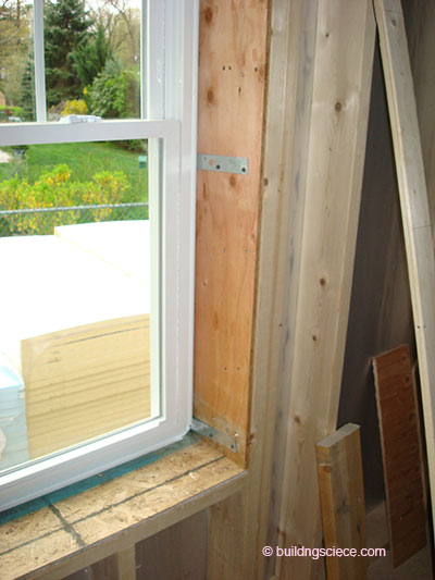
Photograph 3: Strap Window Attachment–Similar to window installation in masonry opens lined with window bucks. Unlike masonry openings the window flanges are retained for water control.
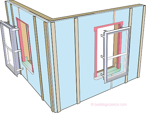
Figure 7: Structural Box–Note that with the structural box the water control layer is wrapped into the box opening and the material is typically flashing tape.
So what if I want to use mineral fiber insulation (stone wool) as my continuous insulation and I want my windows to be “outies”? Note that with mineral fiber insulation the face of the mineral fiber insulation can- not be the water and air control layer. We need that layer to be located behind the mineral fiber insulation—recall our previous discussion. We also need structural sheathing with mineral fiber insulation—no option here either. So we typically turn the structural sheathing into the water and air control layer (go back and check out Figure 4again).
To get the windows to be “outies” with mineral fiber insulation (stone wool) we need to do a couple of things. We need to line the window opening with wood framing that is the thickness of the mineral fiber insulation (stone wool) and this “structural extension” needs to be wide enough on its face to be able to integrate the window flange with the water control layer at the face of the structural sheathing. This is typically 2X material. With 11/2-inch thick mineral fiber insulation (stone wool) the rough opening is “picture framed” with 2×2’s. If you want to go thicker with the continuous mineral fiber insulation (stone wool) use 2×4’s or 2×6’s—trimmed to the correct thickness—for the “picture framing.” Check out the sequence of installation (Figure 8). Note that liquid applied flashing is used to provide continuity with the water control layer on the face of the structural sheathing and the “picture framing” “structural extension.” The liquid-applied flashing wraps into the frame opening and creates the “pan flashing” for the opening. The window installation now follows the same steps as for the “innie” approach.
Figure 8: Window Installation Sequence For Mineral Fiber Installation (Stone Wool)–Note that liquid applied flashing is used to provide continuity with the water control layer on the face of the structural sheathing and the “picture framing” “structural extension”. The liquid applied flashing wraps into the frame opening and creates the “pan flashing” for the opening. The window installation now follows the same steps as for the “innie” approach.
A. Structural sheathing installed over frame wall with opening “picture framed” with 2x material extending past face of sheathing
B. Install beveled wood siding in frame opening at sill to create slope
C. Install liquid-applied flashing wrapping into the frame opening
D. Install window plumb, level and square
E. Install flashing tape at jambs
F. Install flashing tape at head
G. Install continuous insulation
H. Interior view prior to window installation
I. Interior view after window installation
J. Air seal window around entire perimeter with sealant and sealant backer rod
So which are better? “Innies” or “outies”? And what is the correct location of the water control layer? Depends on whom you ask. And when you ask them. It becomes a Ginger or Mary Ann question. There is usually no wrong answer. But regardless of where you end up the water control layer of the wall has to connect to the water control layer of the window.
Footnotes
* A “Straube-ism” . . . after Professor John Straube. He is a master punster. I stole this line from him to make this column work.
- The only folks that recommend the practice are the folks that sell water control layer films (a.k.a. housewraps, water-resistant barrier films and coated papers). The only reason I can come up with as to why is that they don’t want the rest of us to figure out that you don’t need their products if you turn the continuous insulation layer itself into the water control layer.
- Not good if you are in the water control layer film business—but pretty good if you are in the liquid-applied over structural sheathing water control and air control layer business or if you make structural sheathing that is itself the water control and air control layer. Of course, both of these groups hate the continuous insulation people who argue that the continuous insulation can do both on its own. Ah, the marketplace is getting interesting and the squabbles are getting ugly. Each group is trying to screw over the other groups to either hold on to market share or capture market share.
- Pretty sure this is not what Webster’s had in mind for the meaning of “outset.” But what the heck, I have been making things up for years. I coined the phrase “drainage plane” because I needed rhymes that would help architects and consultants understand water control: “you need to drain the rain on the plane” and “don’t be a dope, slope.