Common Advanced Framing Details
Optimum-value engineering (OVE) framing techniques were developed under a Housing and Urban Development (HUD) initiative in the 1960's to cut the cost of houses by omitting unnecessary lumber. The approaches did not get widely adopted at the time. However, with the passage of time, many of the original OVE techniques have been incorporated in what we today refer to as "advanced framing. Advanced Framing includes OVE framing techniques such as increasing joist, stud, and rafter spacing to 24 in.; placing doors and windows on stud layout; and using stacked framing for direct load transfer. Application of advanced framing not only saves on lumber and labor costs, but also supports better insulation detailing and reduces the occurrence of drywall cracking. This information sheet will explain the essential basis for advanced framing and some of the more common advanced framing details.
General Conditions:
Advanced framing, as the name implies, means using the lumber intelligently in wood framing. The foundations of advanced framing are 1. use common material dimensions (24-inch grid) as a basis for design to maximize material use and minimize waste and 2. efficient load transfer to reduce unnecessary framing members from the home. Some of the techniques used include stack framing allowing for the use of single top plates, elimination of wood beams/headers in non-load bearing walls, and two-stud corners. Framing around openings in exterior walls limited to those framing members needed for vertical load transfer (e.g. jack studs) or horizontal load resistance (e.g. king studs where needed around larger openings in larger buildings or high-wind areas).
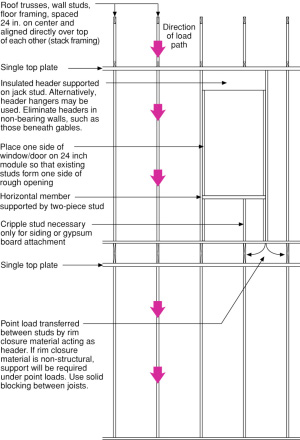
Stack framing elevation view
Exterior Wall Openings:
Structural headers are reserved for bearing wall conditions – they are not needed in non-bearing walls and non-bearing partitions. Headers should be sized appropriately for the load. When possible a single header should be used, however for lager openings a double header may be required. At exterior walls the header should be pushed to the exterior to allow for insulation to be installed on the interior. A framing member on the flat should be used below the header to allow for attaching of the interior drywall. Openings should be aligned with stud spacing (at least one side, preferably two) where possible. Cripple studs are not needed to support sill studs where windows are “hung.” Cripple studs are included at the wall stud spacing intervals for siding or interior finish attachment.
Exterior Wall Corners:
Advanced framing uses a two-stud corner as depicted on the following page. A two-stud corner provides the number of framing members necessary for structural support for most residential. Structural continuity between the two intersecting walls is provided by nailing the two studs together, a connector plate at the top of the wall, and nailing into the floor sheathing at the bottom of the wall. Where structural wall sheathing is needed for shear resistance, this can further connect the intersecting wall assemblies.
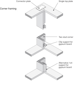
Corner Framing of Exterior Wall
- Thermal bridging by framing is minimized
- Framing cavity space available to insulation is maximized
- Drywall attachment is to one wall only to reduce cracking resulting from differential wood shrinkage. Alternately, use floating corner for the exterior wall.
Single Top Plate:
With stack framing and structural rim board material transferring loads, a double top plate is not needed for load transfer. The framing members must be centered over the studs with a tolerance of no more than 1”.
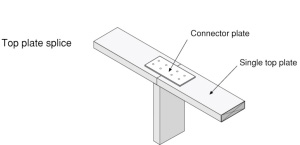
Top Plate Splice Over Stud
- Top plate joint aligned over stud
- Connector plate provides structural continuity to top plate

Top Plate Splice Between Studs
Partition Wall Connection:
Similar to exterior corners, adding additional stud framing for drywall support where partition walls intersect exterior walls creates unnecessary material use and unnecessary thermal bridges. The diagram to the right shows how dry wall support at this intersection can be provided by drywall clips or a 1x6 (alternately, a strip of plywood could be used) attached to the back of the partition’s terminal stud. These measures allow insulation of full, or nearly full-, cavity depth to continue past the intersection. Structural connection between the partition wall and the exterior wall can be achieved by a connector plate at the top of the wall and nailing into the floor sheathing at the bottom of the wall.
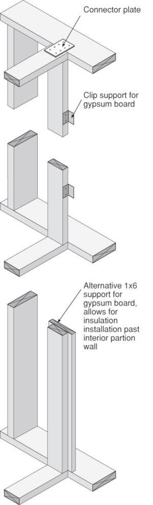
Partition Wall to Exterior Wall Intersection
Thermal bridging by framing at intersection is avoided.
Insulation continues behind intersection.
Drywall attachment is to partition wall only to reduce cracking resulting from differential wood shrinkage. Alternately, use floating corner for one wall.