Introduction
This guide provides information on how to construct vapor diffusion ports when using fiberglass and mineral wool insulation with conditioned unvented attics and unconditioned unvented attics in International Energy Conservation Code (IECC) Climate Zones 1, 2 and 3. The guide follows the requirements of the 2018 and 2021 International Building Code (IBC) and the International Residential Code (IRC).
Conditioned unvented attics are constructed with thermal insulation at the roof deck and the attic space is thermally connected to the building (Figure 1).
Unconditioned unvented attics are constructed with the thermal insulation at the ceiling line and the attic space is not thermally connected to the building (Figure 2).

Figure 1: Conditioned Unvented Attic With Vapor Diffusion Port – Conditioned unvented attics are constructed with thermal insulation at the roof deck and the attic space is thermally connected to the building.
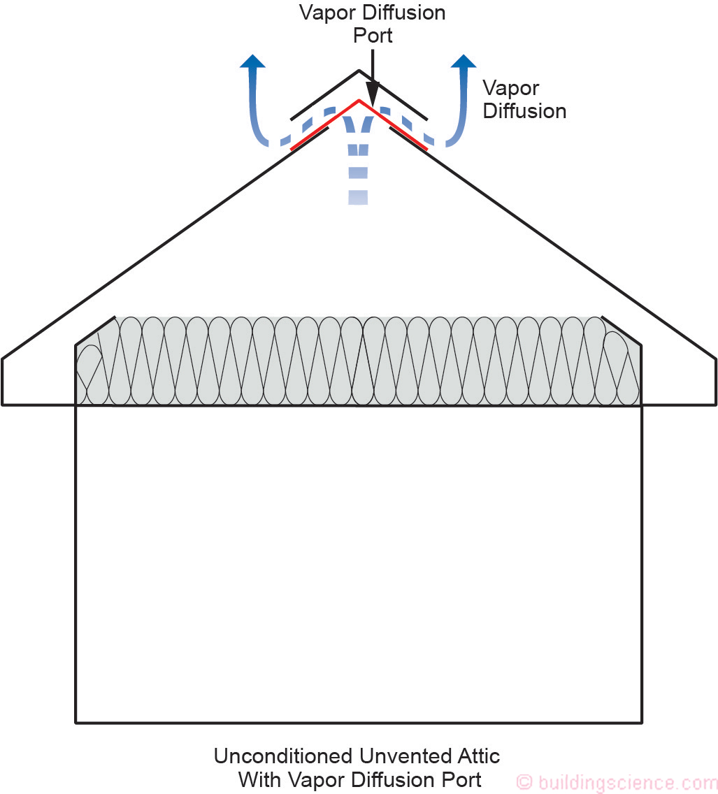
Figure 2: Unconditioned Unvented Attics With Vapor Diffusion Port- Unconditioned unvented attics are constructed with the thermal insulation at the ceiling line and the attic space is not thermally connected to the building.
The research that this guide is based on was developed as part of the Department of Energy’s “Building America Program” and dates back to practices developed in the mid 1990’s in Florida and Texas.
Conditioned unvented attics have certain advantages over unconditioned vented attics. The building enclosure can be made significantly more airtight much easier by constructing an unvented attic, thereby making the building much more energy efficient.
Conditioned and unconditioned unvented attics are also significantly more “fire safe” in wildfire areas and where neighboring buildings are close.
In high wind regions – particularly in coastal areas – wind driven rain is a problem with vented roof assemblies. Unvented roofs – principally due to the robustness of their soffit construction – outperform vented roofs during hurricanes: they are safer.
In coastal areas salt spray and corrosion are a major concern with steel frames, metal roof trusses, and truss plate connectors in vented attics. This is not an issue with unvented attics.
Benefits of Using Fiberglass and Mineral Wool to Construct Conditioned and Unconditioned Unvented Attics
Using fiberglass and mineral wool insulation to construct conditioned and unconditioned unvented attics provides benefits over other approaches to construct conditioned unvented attics. First is fire performance. Fiberglass and mineral wool perform extremely well compared to other insulation materials in fire situations. Next is environmental performance. Fiberglass and mineral wool have low global warming potential (GWP), as they are manufactured and installed without blowing agents. They also have relatively low carbon footprints, contain recycled content, and do not off-gas odors, potentially affecting indoor air quality. Finally, in the event of a roof leak in a conditioned unvented attic constructed with fiberglass and mineral wool. it is much easier to notice the leak, find the leak, and repair the leak. Furthermore, any associated damage may be significantly less. The roof dries much faster when constructed with fiberglass and mineral wool.
IRC and IBC Model Code Language
Using fiberglass and mineral wool insulation to construct conditioned unvented attics and unconditioned unvented attics is permitted in the 2021 IRC (Section R806.5) and the 2021 IBC (Section 1202.3). The language in both the IRC and IBC are substantially the same. The information in this guide satisfies both the 2018 and 2021 versions of both the IRC and IBC.
In “code language,” the words fiberglass and mineral wool insulation are not used – the words “air-permeable insulation” are used instead. The following language is taken from the 2021 IRC (Section R806.5).
Vapor Diffusion Port. An assembly constructed or installed within a roof assembly at an opening in the roof deck to convey water vapor from an unvented attic to the outside atmosphere.
5. 2 In Climate Zones 1, 2 and 3, air-permeable insulation installed in unvented attics shall meet the following requirements.
5.2.1 An approved vapor diffusion port shall be installed not more than 12 inches (305 mm) from the highest point of the roof, measured vertically from the highest point of the roof to the lower edge of the port.
5.2.2. The port area shall be greater than or equal to 1:600 of the ceiling area. Where there are multiple ports in the attic, the sum of the port areas shall be greater than or equal to the area requirements. (see Footnote[1] and Footnote[2])
5.2.3 The vapor-permeable membrane in the vapor diffusion port shall have a vapor permeance rating of greater than or equal to 20 perms when tested in accordance with Procedure A of ASTM E96.
5.2.4 The vapor diffusion port shall serve as an air barrier between the attic and the exterior of the building.
5.2.5. The vapor diffusion port shall protect the attic against the entrance of rain or snow.
5.2.6 Framing members and blocking shall not block the free flow of water vapor to the port. Not less than a 2-inch (51 mm) space shall be provided between any blocking and the roof sheathing. Air-permeable insulation shall be permitted within that space. (see Footnote[3])
5.2.7 The roof slope shall be greater than or equal to 3:12 (vertical/horizontal)
5.2.8 Where only air-permeable insulation is used, it shall be installed directly below the structural roof sheathing, on top of the attic floor, or on top of the ceiling.
5.2.9 Air-impermeable insulation, if used in conjunction with air-permeable insulation, shall be directly above or below the structural roof sheathing and is not required to meet the R-value in Table 806.5. Where directly below the structural roof sheathing, there shall be no space between the air-impermeable insulation and air permeable insulation. (see Footnote[4]).
5.2.10 Where only air-permeable insulation is used and is installed directly below the roof structural sheathing, air shall be supplied at a flow rate greater than or equal to 50 CFM (23.6 L/s) per 1,000 square feet (93 m2) of ceiling area. The air shall be supplied from ductwork providing supply air to the occupiable space when the conditioning system is operating. Alternatively, the air shall be supplied by a supply fan when the conditioning system is operating.
5.2.11 If both air-impermeable and air-permeable insulation are used, and the requirements of Table 806.5 are met, then air supply to the attic is not required. Otherwise the air supply requirements of 5.2.10 shall apply when both air-impermeable and air-permeable insulation are used.
Vapor Diffusion Ports
A vapor diffusion port is basically a standard ridge vent or off-ridge vent where the opening in the roof deck is covered with an airtight, water tight but vapor open layer. Think of this layer as a “house wrap or building wrap” for your vent. It “breathes” vapor but keeps the outside air out and the rain out.
Unvented attics can be insulated on the bottom of a roof deck (conditioned attic) and attics can be insulated on the top of ceilings or attic floors (unconditioned attic) using fiberglass and mineral wool insulation. The approaches constructing vapor diffusion ports are different for each approach.
There are limitations to these approaches based on climate and roof slope. The approach is limited to hot-dry and hot-humid climates (IECC Climate Zones 1, 2 and 3). Additionally, the roof must be sloped to allow moisture buoyancy to work – the roof slope must be greater than or equal to 3:12 (vertical/horizontal).
Installing a “vapor diffusion port” at the upper part of attic spaces and sloping rafter roof assemblies allows moisture (in the vapor phase) to exit the attic and roof assembly. In practice, this involves eliminating the lower soffit attic/roof vents, while installing standard roof vents near the ridge, but covering the vent opening in the roof deck with an airtight but vapor open layer.
Two types of vapor diffusion port configurations are used. The first are ridge port openings located at roof ridge lines and hips (Figure 3). The second are off-ridge port openings located at the upper part of attics but not on ridges or hips (Figure 4).
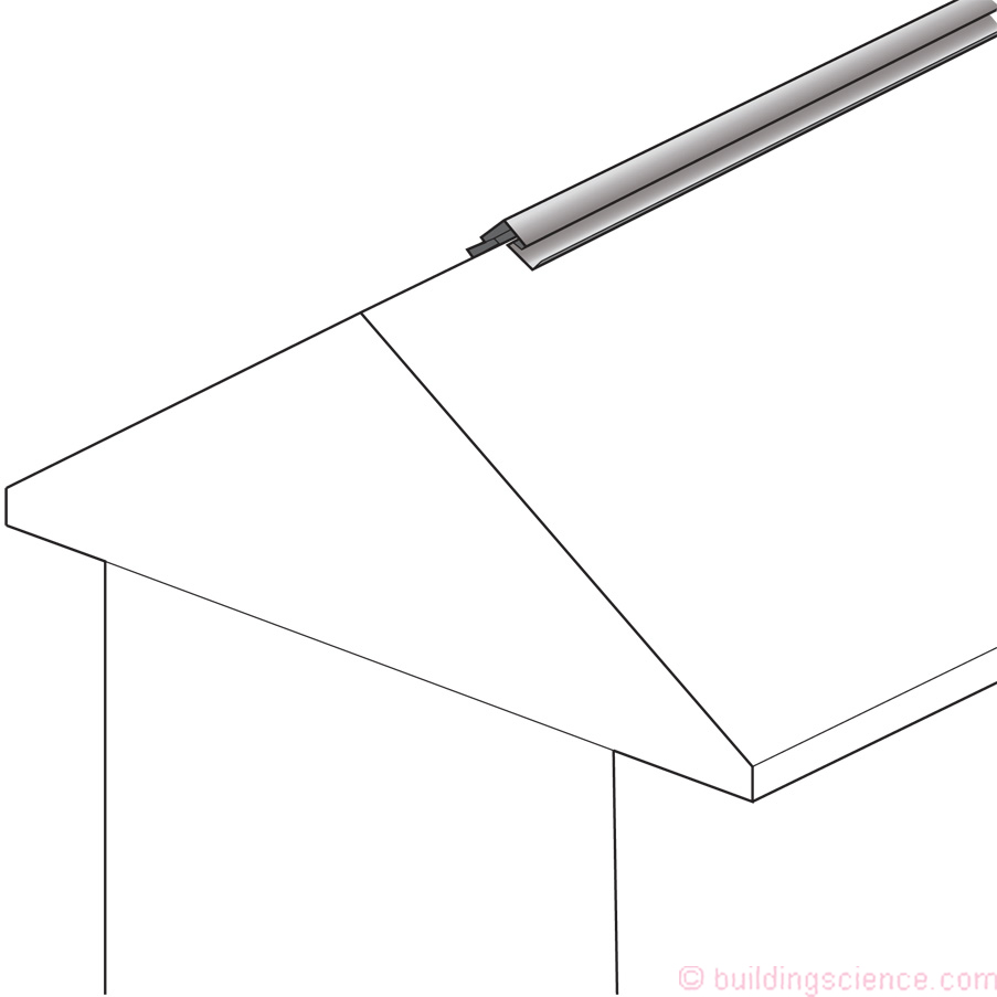
Figure 3: Ridge Port Openings - Ridge port openings located at roof ridge lines and hips. Ridge port openings can be used for both conditioned unvented attics and unconditioned unvented attics. Ridge port openings are analogous to the omitted sheathing used in typical vented roof ridge vents.
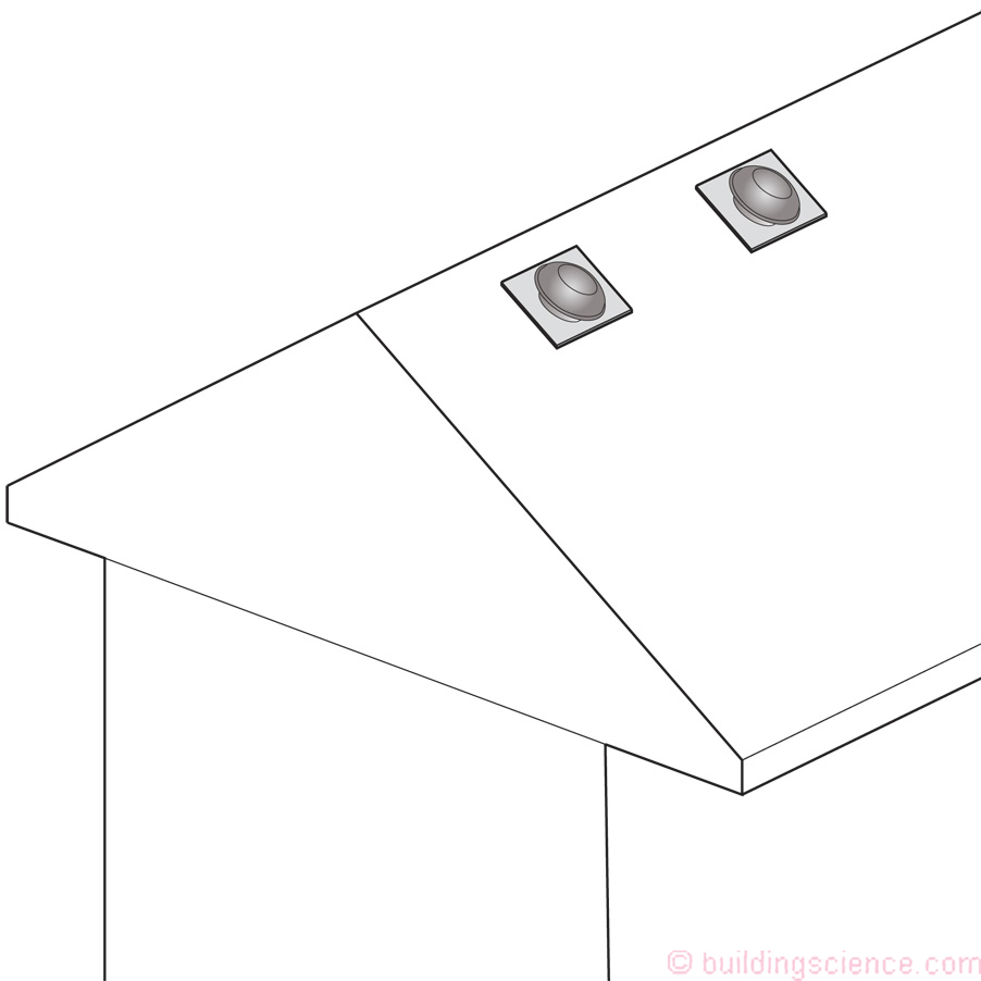
Figure 4: Off-Ridge Port Openings - Off-ridge port openings located at the upper part of attics but not on ridges or hips. Off-ridge port openings can only be used for unconditioned unvented attics – where the insulation is located at the ceiling line. Off-ridge port openings are analogous to typical “button” vents, “mushroom” vents, off-ridge vents, and rooftop intake/exhaust vents.
Ridge port openings are analogous to the omitted sheathing used in typical vented roof ridge vents. Off-ridge port openings are analogous to typical “button” vents, “mushroom” vents, off-ridge vents, and rooftop intake/exhaust vents.
Ridge port openings can be used for both conditioned unvented attics and unconditioned unvented attics. Off-ridge port openings can only be used for unconditioned unvented attics – where the insulation is located at the ceiling line.
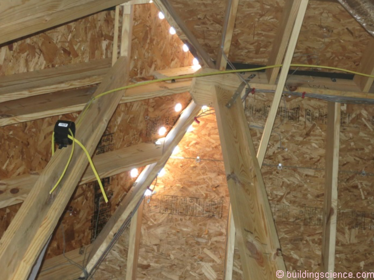
Where insulation is located at the underside of roof sheathing each rafter bay or truss bay requires a vent at the ridge line and at the upper portion of hips. This is necessary to provide a vapor diffusion moisture pathway to the exterior for each rafter bay or truss bay. Note code section 5.2.6: “Framing members and blocking shall not block the free flow of water vapor to the port. Not less than a 2-inch (51 mm) space shall be provided between any blocking and the roof sheathing. Air-permeable insulation shall be permitted within that space” (2021 IRC (Section R806.5).
Where insulation is located at the ceiling line intermittent vents providing the appropriate vent area can be located at the upper portion of the attic but not at the ridge line or at the upper portion of hips. Since the insulation is not installed at the underside of the roof sheathing it is easy for moisture to access distributed off-ridge port openings.
Vapor Diffusion Ridge Port Openings
Two types of vapor diffusion ridge port openings are typical – strip port openings and round port openings – depending on structural requirements (Figure 5, Figure 6, Figure 7 and Figure 8) (Photograph 1, Photograph 2, Photograph 3 and Photograph 4). Ridge strip port openings are analogous to the omitted sheathing used in typical vented roof ridge vents. However, standard ridge vent openings can compromise roof deck diaphragm (“shear”) resistance. Using round openings in roof sheathing addresses this issue (Photograph 5 and Photograph 6). Round openings are typically used at roof hip assemblies to maintain the roof deck structural diaphragm. A standard roof vent is extended downward along the hip a minimum of 2 feet (Figure 9). The model code language does not address hip roof details. However, experience in practice indicates that a minimum extension of 2 feet is necessary. Similar approaches are used for dormer roofs.
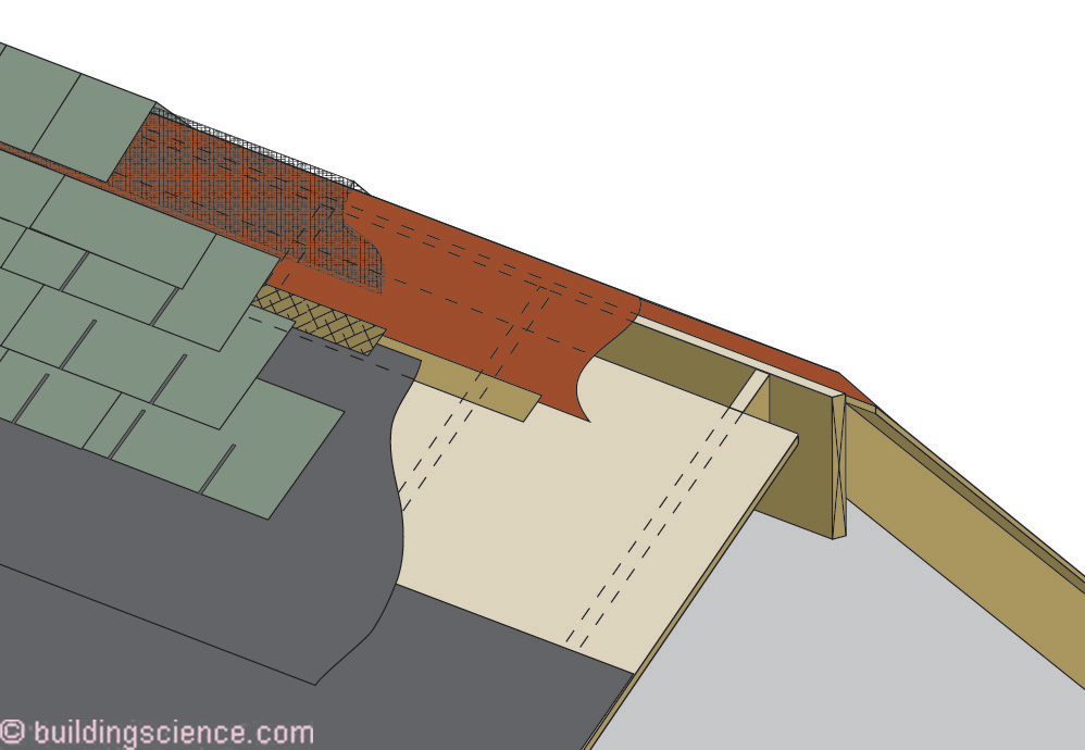
Figure 5: Vapor Diffusion Ridge Port Openings (Strip Port Openings) Shingle Roofs – Standard roof vents located at the ridge, but with the opening in the roof deck covered with an airtight but vapor open layer.
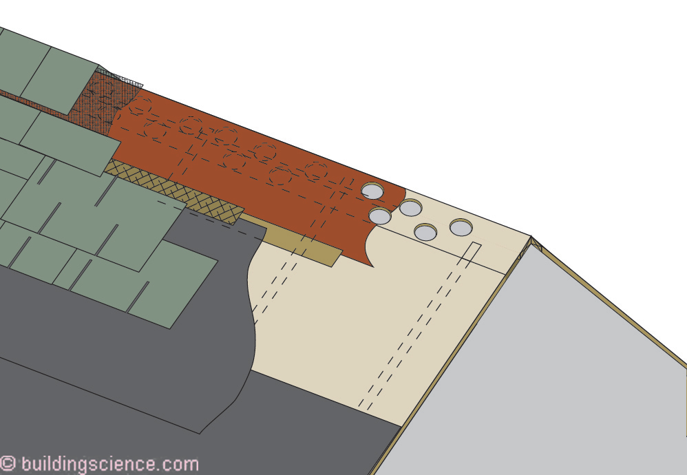
Figure 6: Vapor Diffusion Ridge Port Openings (Round Port Openings) Shingle Roofs – Holes near ridge through sheathing to maintain structural diaphragm, covered with an airtight but vapor open layer.
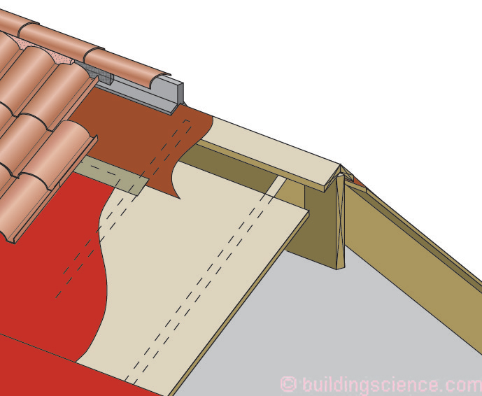
Figure 7: Vapor Diffusion Ridge Port Openings (Strip Port Openings) Tile Roofs - Standard roof vents located at the ridge but with the opening in the roof deck covered with an airtight but vapor open layer.
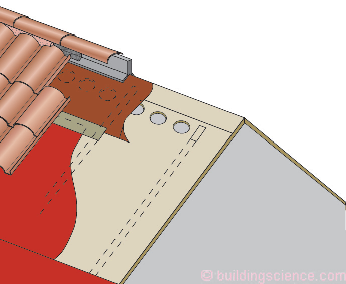
Figure 8: Vapor Diffusion Ridge Port Openings (Round Port Openings) Tile Roofs - Holes near ridge through sheathing to maintain structural diaphragm, covered with an airtight but vapor open layer.
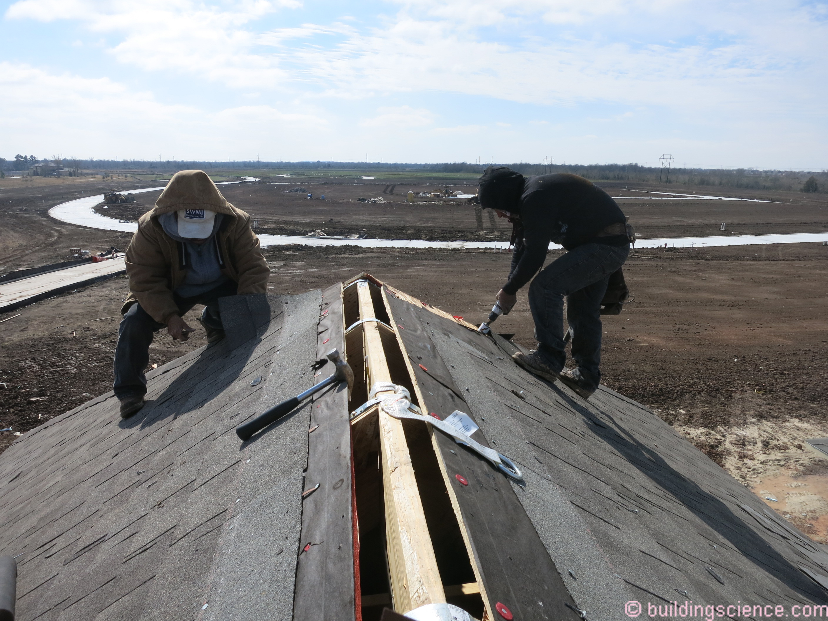
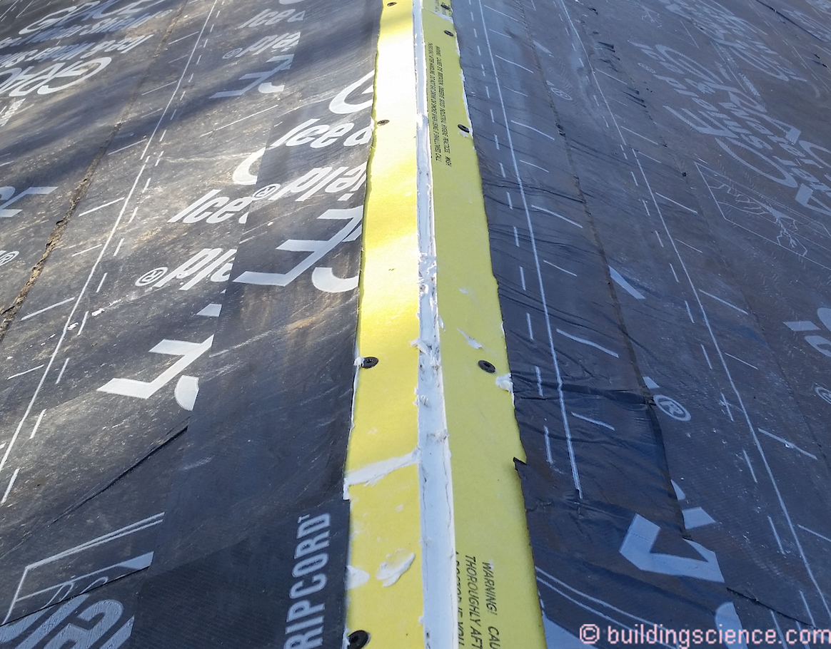
Photograph 1: Vapor Diffusion Port (Strip Port Openings) Asphalt Roofs - Standard roof vent opening located at the ridge.
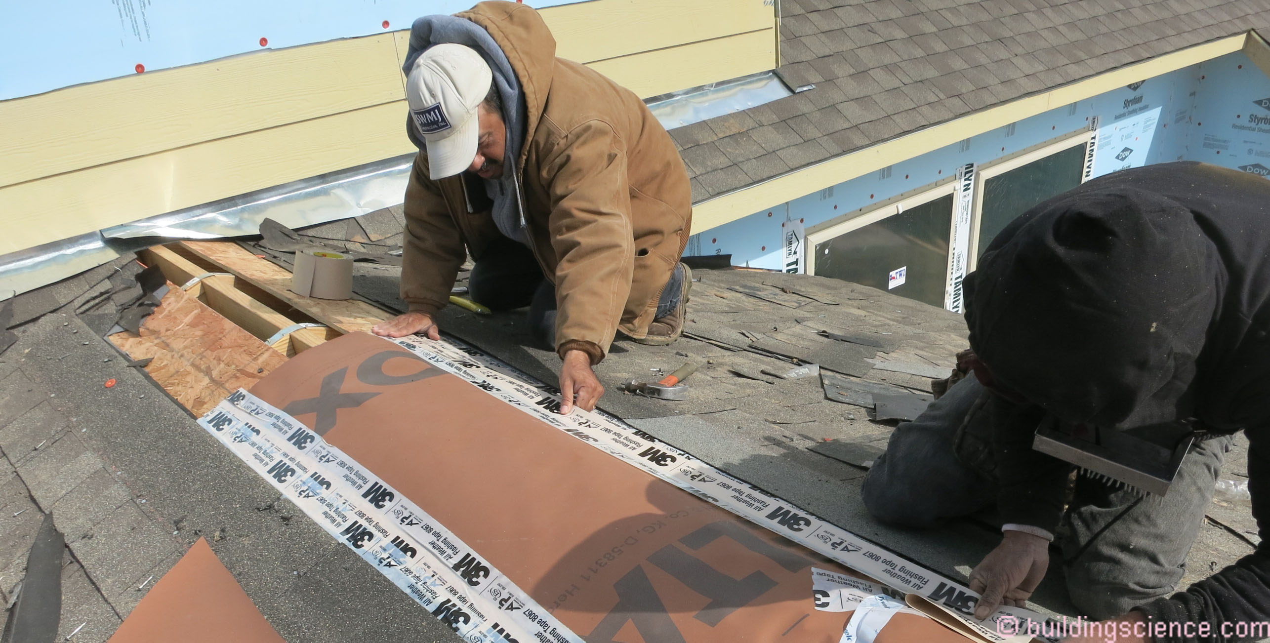
Photograph 2: Vapor Open Layer – Port opening in the roof deck covered with a water tight and airtight but vapor open layer.
Photograph 3: Standard Ridge Vent – A standard ridge vent is installed over the water tight and airtight and vapor open layer.
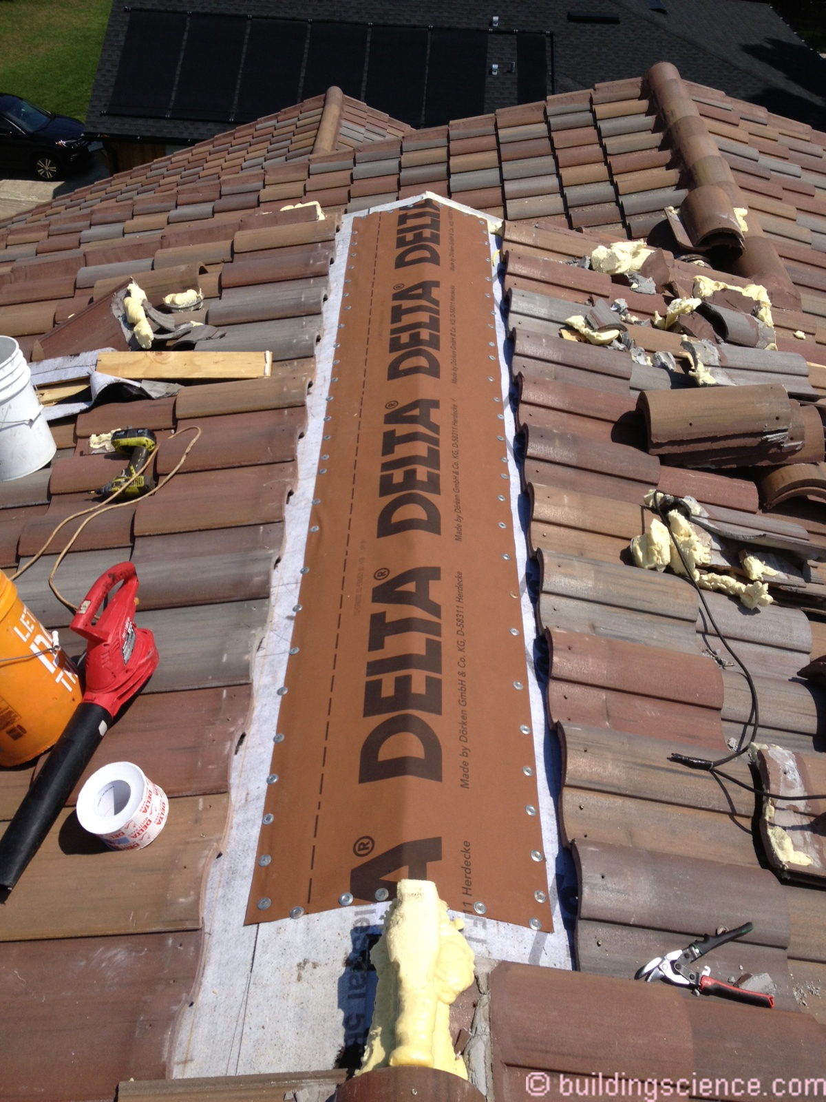
Photograph 4: Tile Roof Opening – Watertight and airtight and vapor open layer being installed.
Photograph 5: Round Port Openings at Hip Roof – View from underneath the roof assembly showing the location of the round port openings at the upper part of the hip roof assembly.
Photograph 6: Fireproof Diffusion Port Layer – Exterior rated gypsum board can be used for the water tight, air tight and vapor open layer.
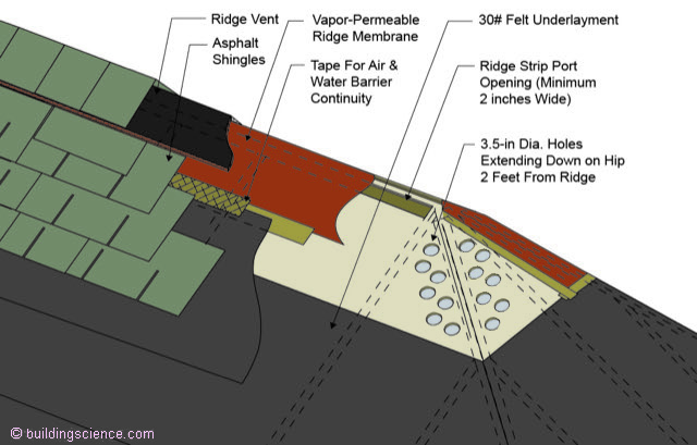
Figure 9: Hip Roof Assemblies - Round openings are typically used at roof hip assemblies to maintain the roof deck structural diaphragm. Standard roof vent extended downward along the hip a minimum of 2 feet.
Skylight and dormer openings need to be framed in a manner that allows vapor to migrate around the opening (Figure 10).
An alternate approach to using round diffusion port openings for hip roof construction is to use smaller hip rafters and doubling them up to provide a vapor path up the hip assembly (Figure 11).
Shed roofs use notched rafters and use diffusion ports at gable ends (Figure 12).
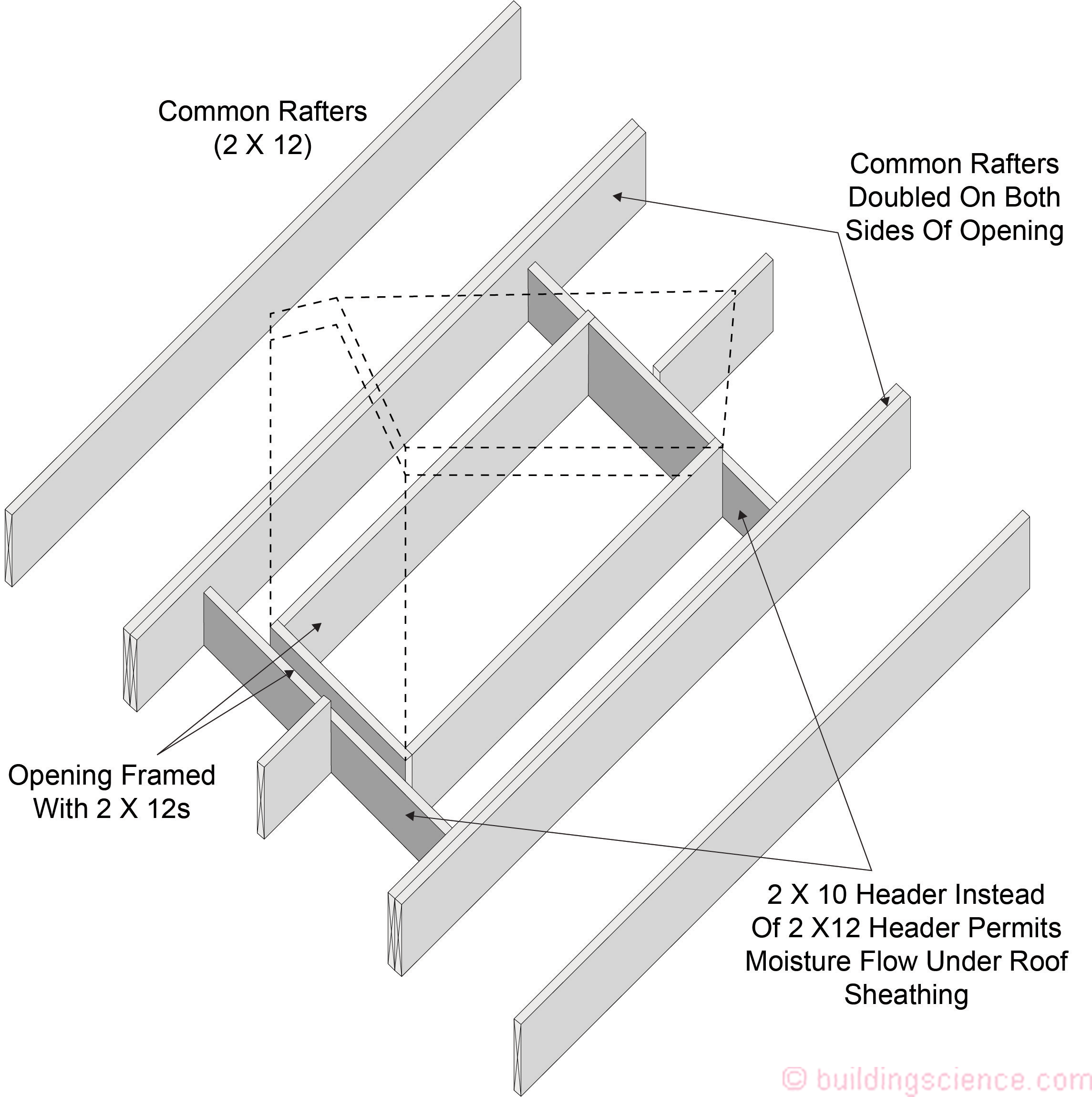
Figure 10: Skylight and Dormer Openings – These openings need to be framed in a manner that allows vapor to migrate around the opening. This can be accomplished by dropping the size of the “headers”.
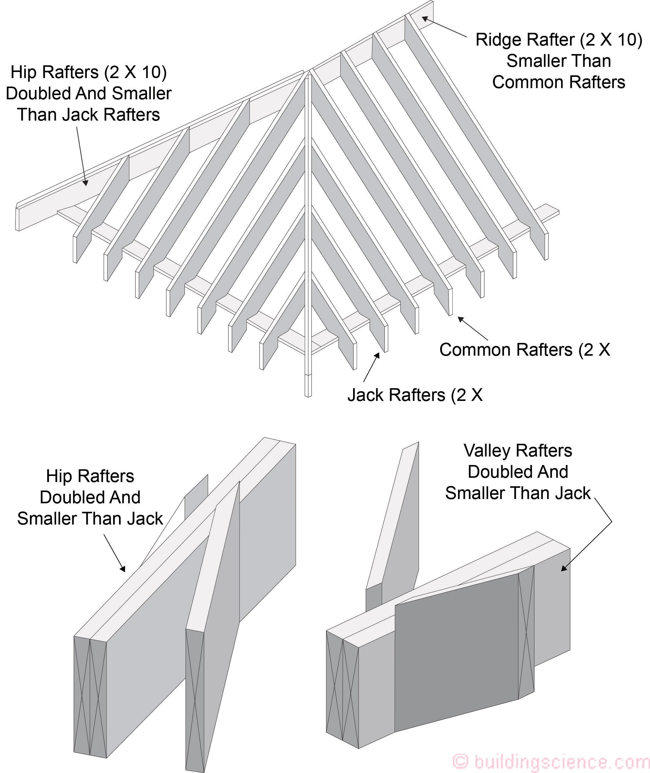
Figure 11: Hip Rafter Framing - An alternative approach to using round diffusion port openings for hip roof construction is use smaller hip rafters and doubling them up to provide a vapor path up the hip assembly.
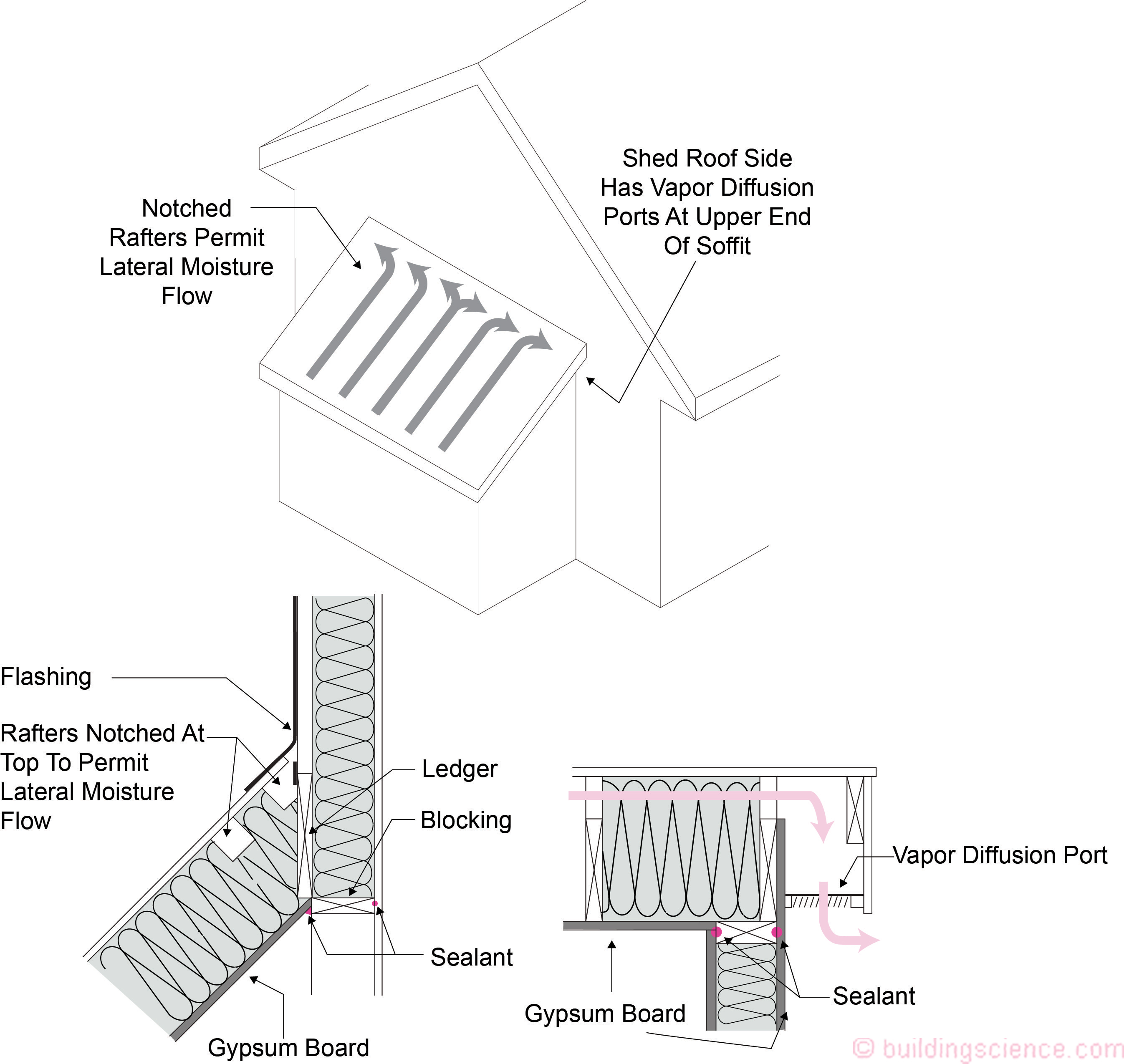
Figure 12: Shed Roofs - Shed roofs use notched rafters and use diffusion ports at gable ends.
Constructing Vapor Diffusion Ports – Ridge Roof Assembly With Dormer
Consider a typical ridge roof assembly with a dormer (Figure 13) along with the roof plan and roof framing plan (Figure14). It is proposed to install a vapor diffusion ridge port “strip port opening” port configuration as configured on Figure 14. In this configuration the shed roof dormer vents into the strip port opening.
Figure 13: Ridge Roof Assembly With Dormer
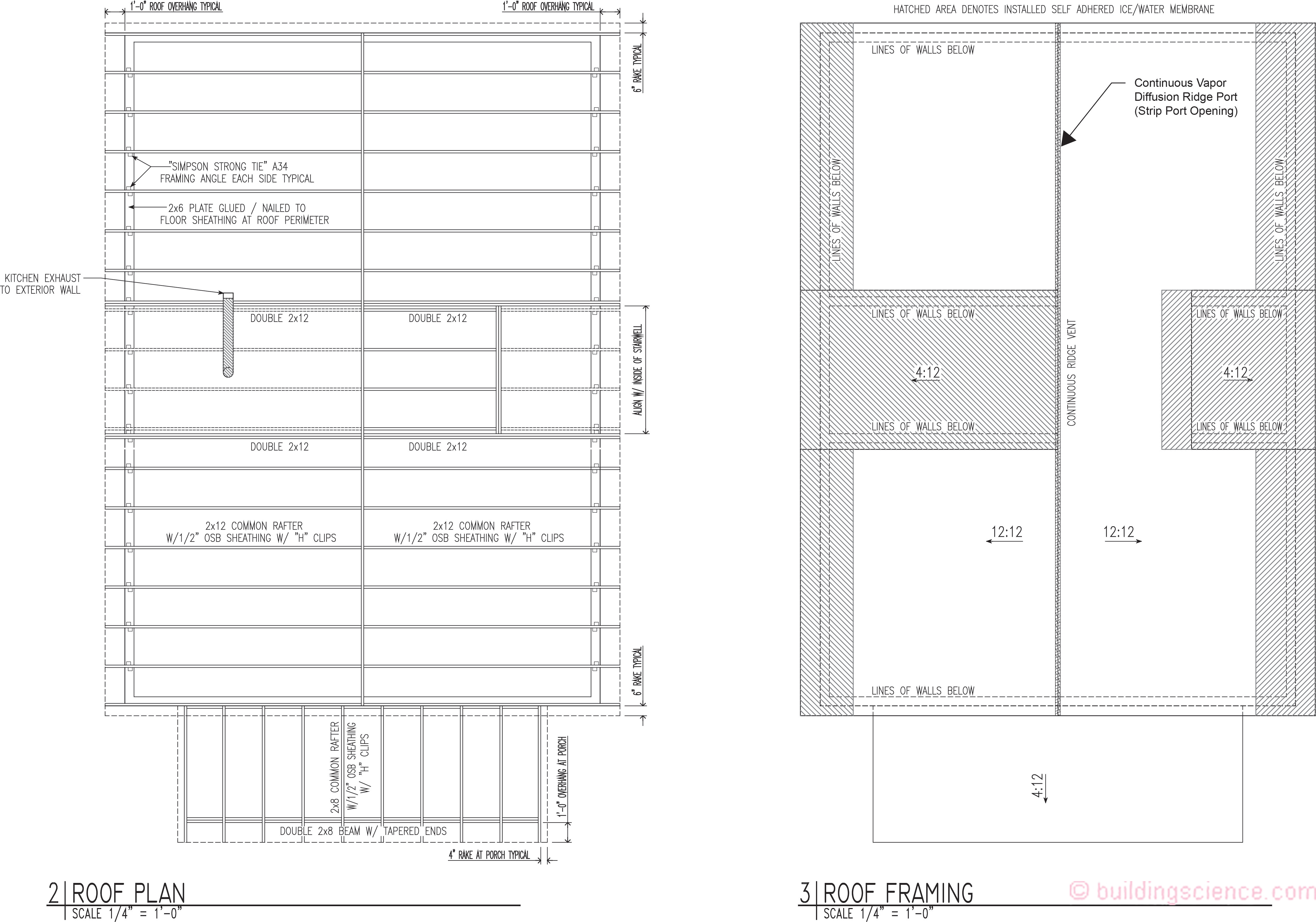
Figure 14: Roof Plan And Roof Framing Plan – Installation of a vapor diffusion ridge port “strip port opening” configuration. In this configuration the shed roof dormer vents into the strip port opening.
The first step is to determine roof slope. The model codes call for the roof to be sloped a minimum of 3:12 or greater. The roof assembly meets this requirement.
The next step is to determine the area and geometry of the strip port.
The dimensions of the roof ceiling area are 34 feet by 24 feet (816 square feet).
This guide’s requirement is a “port area shall be greater than or equal to 1:150 of the ceiling area”. Divide 816 square feet by 150 square feet to yield 5.44 square feet (approximately 780 square inches).
The available ridge length for venting is 34 feet (408 inches).
Dividing 780 square inches by 408 inches yields a “strip port opening width” of approximately 2 inches.
At the ridge a 3 inch strip of roof sheathing is omitted on each side leaving an opening of approximately 2 inches on each side of the ridge beam.
If round port openings are used then 5 openings each 3.5 inches in diameter should be provided in every 24 inch rafter or truss bay on each side of the ridge beam to provide equivalent port area to the recommended strip width described above (2 gaps 2 inches wide – one gap on each side of the ridge beam). The area of a 3.5 inch diameter opening is approximately 10 square inches (Pi x r2)(3.14 times 1.75 times 1.75). The area on each side of the ridge beam in the strip approach per rafter bay or truss bay is 48 square inches. Divide 48 square inches by 10 square inches yielding 5 openings.
The vapor permeance of the diffusion port covering should be greater than or equal to 20 perms.
The edges of the permeable roof membrane should be taped to the OSB roof sheathing to create an air barrier (while allowing vapor diffusion). Additionally, any joints in the permeable roof membrane need to be sealed – also to create an air barrier. Based on multi-substrate adhesion testing, a high performance acrylic adhesive flashing tape should be used.
The remaining field of the roof is “dried-in” using typical underlayment for asphalt shingles.
The top edge of the roof underlayment creates a reverse lap situation (for bulk water drainage) at the intersection with the permeable roof membrane. The connection should be sealed with acrylic adhesive flashing tape.
Asphalt shingles are installed on the roof as per typical practice.
The ridge is covered with a typical attic ridge exhaust vent material which is in turn covered by ridge cap shingles.
Constructing Vapor Diffusion Ports – Hip Roof Assembly
Consider a typical hip roof assembly (Figure 15) along with the roof plan and roof framing plan (Figure 16). It is proposed to install a vapor diffusion ridge port “strip port opening” port configuration at the ridge and round port openings at the hips extending downward 2 feet from the ridge as configured on Figure 16.
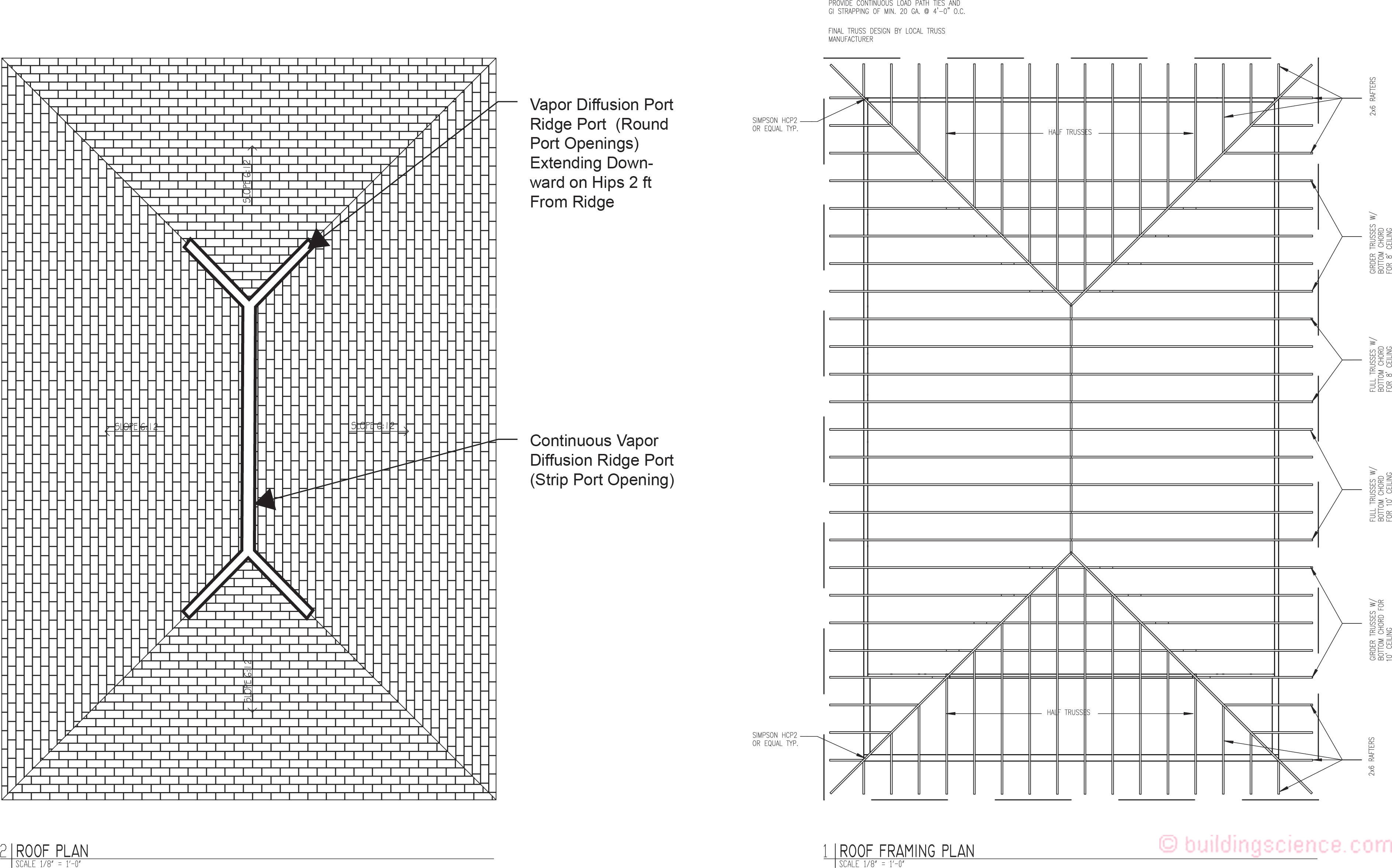
Figure 16: Roof Plan and Roof Framing Plan - Installation of a diffusion ridge port “strip port opening” configuration at the ridge and round port openings at the hips extending downward 2 feet from the ridge.
The first step is to determine roof slope. The model codes call for the roof to be sloped a minimum of 3:12 or greater. The roof assembly meets this requirement.
The next step is to determine the area and geometry of the strip port.
The dimensions of the roof ceiling area are 42 feet by 30 feet (1260 square feet).
The model code requirement is a “port area shall be greater than or equal to 1:600 of the ceiling area”. Divide 1260 square feet by 150 square feet to yield 8.4 square feet (approximately 1,200 square inches).
The available ridge length for venting is 16 feet (192 inches).
Dividing 1,200 square inches by 192 inches yields a “strip port opening width” of approximately 6 inches.
At the ridge a 4 inch strip of roof sheathing is omitted on each side leaving an opening of approxiamtely 3 inches on each side of the ridge beam.
If round port openings are used then 5 openings each 3.5 inches in diameter should be provided in every 24 inch rafter or truss bay on each side of the ridge beam to provide equivalent port area to the recommended strip width described above (2 gaps 2 inches wide – one gap on each side of the ridge beam).
The area of a 3.5 inch diameter opening is approximately 10 square inches (Pi x r2)(3.14 times 1.75 times 1.75). The area on each side of the ridge beam in the strip approach per rafter bay or truss bay is 72 square inches. Divide 72 square inches by 10 square inches yielding 7 openings.
For the round port openings at the hips extending downward 2 feet from the ridge 7 openings each 3.5 inches in diameter should be provided in every 24 inch rafter or truss bay on each side of the hip.
The vapor permeance of the diffusion port covering should be greater than 20 perms.
The edges of the permeable roof membrane should be taped to the OSB roof sheathing to create an air barrier (while allowing vapor diffusion). Based on multi-substrate adhesion testing, a high performance acrylic adhesive flashing tape should be used.
The remaining field of the roof is “dried-in” using typical underlayment for asphalt shingles.
The top edge of the roof underlayment creates a reverse lap situation (for bulk water drainage) at the intersection with the permeable roof membrane. The connection should be sealed with acrylic adhesive flashing tape.
Asphalt shingles are installed on the roof as per typical practice.
The ridge is covered with a typical attic ridge exhaust vent material which is in turn covered by ridge cap shingles.
Air Supply to Attic Space Providing Conditioning
Where the insulation is installed on the underside of the roof deck and the insulation is “air permeable,” then HVAC supply air should be provided to the attic space from the interior of the house to remove moisture, by providing “conditioning” to the attic space, thereby treating it similar to a room or occupied space. At least 50 cfm for each 1,000 ft2 of ceiling area is required. This airflow does not need to be continuous. The typical 30 percent duty cycle of air conditioning system operation has been found to be effective. Alternatively, a dehumidifier can be installed. For attic spaces that are approximately 1,000 ft2 or less a typical 6 inch diameter supply air duct should be provided. For attic spaces that are greater than 1,000 ft2 – two 6 inch supply air ducts should be provided.
Additional Issues to Consider When Constructing Unvented Attics
Combustion Safety
When constructing conditioned unvented attics and unconditioned unvented attics, it is critical that only sealed combustion appliances such as gas furnaces and gas water heaters are installed in such unvented attics. This holds true when retrofitting existing vented attics and converting them to unvented attics.
Effect on Shingle Life
In general, asphalt shingles installed on unvented attic assemblies operate at a slightly higher temperature. This has impacts on the durability of roof assemblies. A 2 or 3 degree F rise in average temperature is typical for asphalt shingles, and a corresponding 10 degree F. rise in average temperature for sheathing. As such, a 10 percent reduction in useful service life for asphalt shingles should be expected. This is comparable to the effect of the installation of radiant barriers. What is more significant to note is that the color of shingles and roof orientation have a more profound effect on the durability of shingles than the choice of venting or not venting – double or triple the effect of venting vs. not venting.
Inward Moisture Drive
Inward moisture drive through asphalt shingles under various configurations/permeabilities of roofing underlayments and under deck insulation systems is not significant to the moisture balance of the roof sheathing from a durability/long term service life perspective, the latent load of the building, or surface condensation.
Hurricanes and WildFires
One of the most damaging effects of hurricanes in the southeast is wind driven rain through roof vents. Various estimates indicate that 20 to 30 percent of hurricane water damage occurs through leaking roof vents. One successful strategy is to construct unvented roof assemblies in these areas. Another successful strategy is to not install soffit vents (or to seal up existing soffit vents in retrofit applications), and install upper vapor diffusion vents (or sealing the upper vents with a water tight but vapor open membrane or sheet good in retrofit applications).
In wildfire areas, the major concern are embers entering vented roofs carried by air currents. It is possible to seal lower vents and then install a vapor open membrane or sheet good covering the upper openings that is also fire resistant, such as exterior fiber faced gypsum board or a fireproof vapor open membrane. In California, requirements for the resistance of embers and flames are outlined in Chapter 7A and products are listed for such applications.
Sweating Ductwork
In hot-humid climates, an increasingly common problem in vented attics is condensation (“sweating”) on attic ductwork and mold growth on attic sheathing and framing members. In addition, “burying” ductwork under attic insulation can greatly improve thermal performance, but has the potential to create moisture risks if implemented incorrectly. One approach to controlling ductwork sweating and burying standard ductwork and boots (insulated to less than R-13 in IECC Climate Zones 1A, 2A, 3A) is to construct unconditioned unvented attics.
References
Lstiburek, J.W.; Venting vapor, ASHRAE Journal, July 2015.
https://www.buildingscience.com/documents/insights/bsi-088-venting-vapor
Lstiburek, J.W.; No sweat, ASHRAE Journal, April 2016.
https://www.buildingscience.com/documents/building-science-insights-newsletters/bsi-094-no-sweat
Lstiburek, J.W.; Hybrid assemblies, ASHRAE Journal, October 2017.
https://www.buildingscience.com/documents/building-science-insights/bsi-100-hybrid-assemblies
Ueno, K and Lstiburek, J.W.; Building America Report: Field testing of an unvented roof with fibrous insulation, tiles, and vapor diffusion venting, Building Science Corporation, November 2015.
Ueno, K and Lstiburek, J.W.; Building America Report: Field testing of unvented roofs with asphalt shingles in cold and hot-humid climates, Building Science Corporation, June 2015.
Ueno, K and Lstiburek, J.W.; Monitoring of two unvented roofs with air-permeable insulation in Climate Zone 2A; Thermal Performance of the Exterior Envelopes of Whole Buildings XIII International Conference, Clearwater, FL, December, 2016.
Footnotes
[1] Although the code calls for the port area to be greater than 1:600 of the ceiling area this guide recommends that the port area to be greater than 1:150 of the ceiling area.
[2] The ceiling area refers to the “flat ceiling of the building”…the “floor” of the attic…even if the ceiling is sloped.
[3] The 2 inch opening should be continuous between rafter or truss member framing.
[4] This insulation is necessary for condensation control.