Yes, we have done unvented conditioned attics before….but mostly with spray foam and rigid foam insulations. But we do not have to use spray foam and rigid foam insulations. You can use almost anything….as long as you follow a few rules. OK, not so much rules, but experience based on measurements and field performance. Real world stuff.[1]
Attics can be insulated on the top of ceilings or attic floors. Additionally, attics or roofs can be insulated on the top of a roof deck, on the bottom of a roof deck and both on the top and bottom of a roof deck.
Attics can be designed and constructed to be either vented or unvented in any climate zone. The choice of venting or not venting is a design and construction choice—not a requirement determined by the building code. The model codes allow both vented and unvented attic assemblies.
Unvented attics are also often referred to as conditioned attics – when they are part of the house that is heated and cooled – and when the insulation is at the roof deck (directly under it, directly on top of it, or a combination of both). Note that unvented attics do not always have to be conditioned. This occurs when the attic is unvented and the insulation is at the ceiling – they are not part of the house that is heated and cooled. The model codes allow both conditioned and unconditioned attics. More specifically, the model codes allow conditioned unvented attics with fiberglass and mineral wool (Figure 1) and unconditioned unvented attics with fiberglass and mineral wool (Figure 2). But there are pretty specific requirements as we will point out.
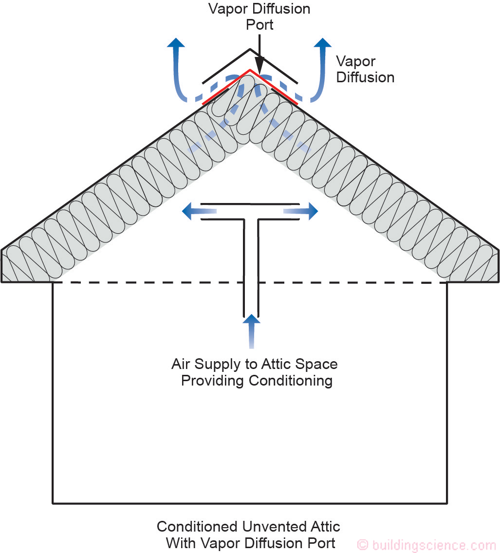
Figure 1: Conditioned Unvented Attic With Vapor Diffusion Port – Conditioned unvented attics are constructed with thermal insulation at the roof deck and the attic space is thermally connected to the building.
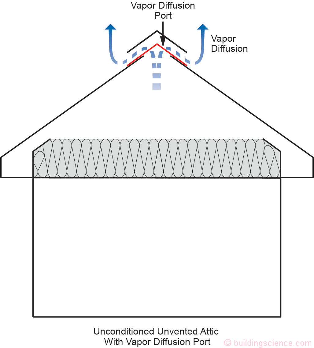
Figure 2: Unconditioned Unvented Attics With Vapor Diffusion Port- Unconditioned unvented attics are constructed with the thermal insulation at the ceiling line and the attic space is not thermally connected to the building.
First, some background. Conditioned unvented attics have significant advantages over unconditioned vented attics. The building enclosure can be made significantly more airtight much easier by constructing an unvented attic, thereby making the building much more energy efficient. Ductwork and air handlers typically leak, leading to significant negative pressures in buildings when they are located in vented attics (Figure 3). By installing insulation on the underside of the attic roof sheathing, any ductwork or mechanical systems installed in attics are now located “inside” rather than “outside,” again making the building much more energy efficient (Figure 4).
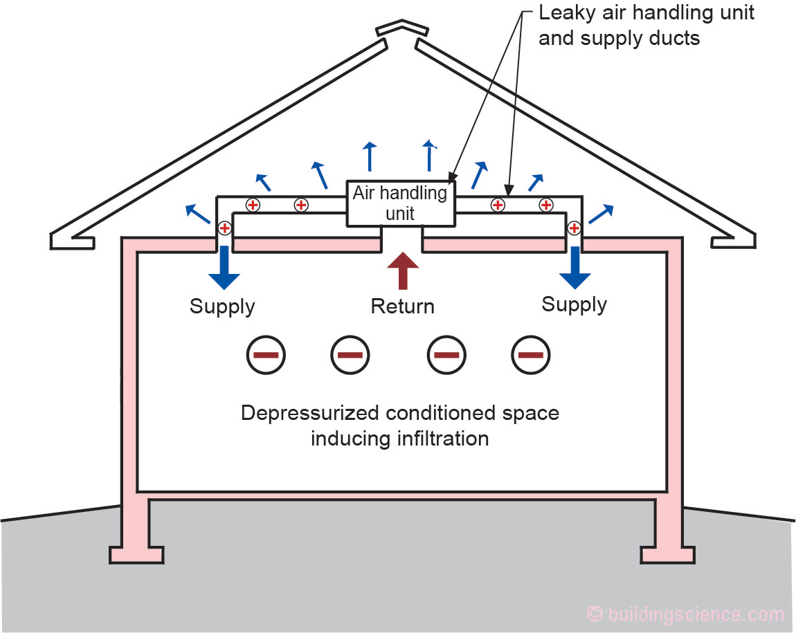
Figure 3: HVAC Systems in Vented Attics - Ductwork and air handlers typically leak air, which leads to significant negative pressures in buildings when they are located in vented attics, with resulting energy penalties.
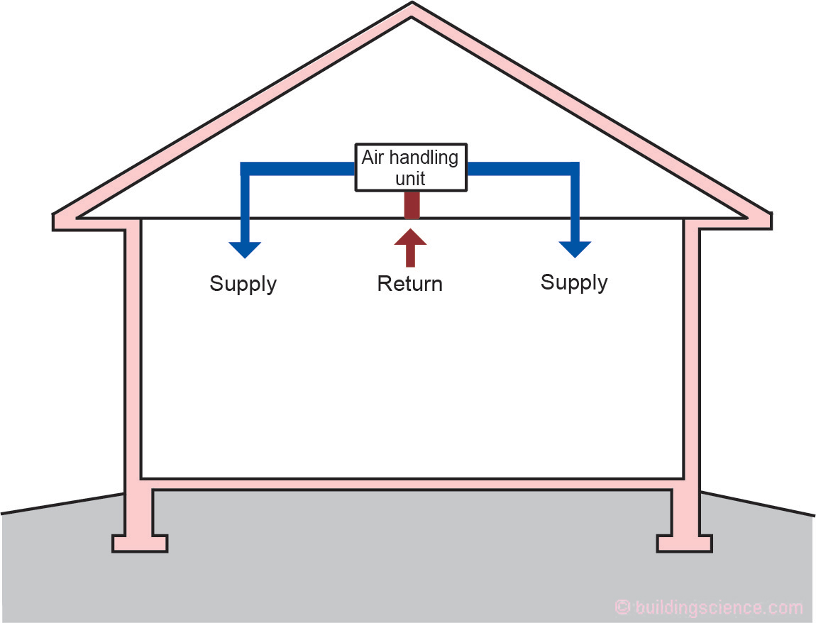
Figure 4: Conditioned Unvented Attics - Conditioned unvented attics have significant advantages over unconditioned vented attics. The building enclosure can be made significantly more airtight much easier by constructing an unvented attic, thereby making the building much more energy efficient.
Unvented attics are also significantly more “fire safe” in wildfire areas and where neighboring buildings are close. Ash and embers enter typical attics through attic vents. No vents means no ash or embers entering attics, and much less risk of fire.
In high wind regions – particularly in coastal areas – wind driven rain is a problem with vented roof assemblies. Additionally, during high wind events, vented soffit collapse leads to building pressurization and window blowout and roof loss due to increased uplift. Unvented roofs – principally due to the robustness of their soffit construction – outperform vented roofs during hurricanes: they are safer.
In coastal areas salt spray and corrosion are a major concern with steel frames, metal roof trusses, and truss plate connectors in vented attics. This is not an issue with unvented attics.
Then why ever build a vented attic? Historically, there were good reasons. The first and foremost reason was to control moisture in attic spaces. However, we have learned how to control moisture in unvented conditioned attics. In hot humid climates we have found that attic venting actually causes moisture problems. Attic venting in hot humid climates brings in outdoor hot humid air into attic spaces, making ductwork sweat and causing mold growth on roof sheathing and roof framing.
The second reason was for comfort during the summer. Before the introduction of air conditioning and attic insulation, venting an attic reduced the temperature inside of houses. With the advent of high levels of attic insulation and the introduction of air conditioning, venting attics no longer saves energy. Today, in modern vented and insulated attics, the dominant form of heat transfer is radiation from the underside of the roof deck to the top of attic ceiling insulation. Ventilation does not affect this heat exchange. The color of the roofing and the type of roofing are more important in controlling radiant heat exchange in an attic than attic venting. Radiant barriers are a common mechanism for directly addressing radiation transfer.
The third reason was to control ice-damming. And yes, we were here before (“BSI-046: Dam Ice Dam”, February 2011 and “BSI-097 De-Icing Ice Dams”, October 2018).
Controlling Moisture in Unvented Attics
The key to unvented attic and roof assemblies is to control condensation or moisture accumulation on the underside of the roof sheathing. This can be done several ways. One way is to raise the temperature of the roof sheathing by insulating on the top of the roof sheathing (Figure 5).
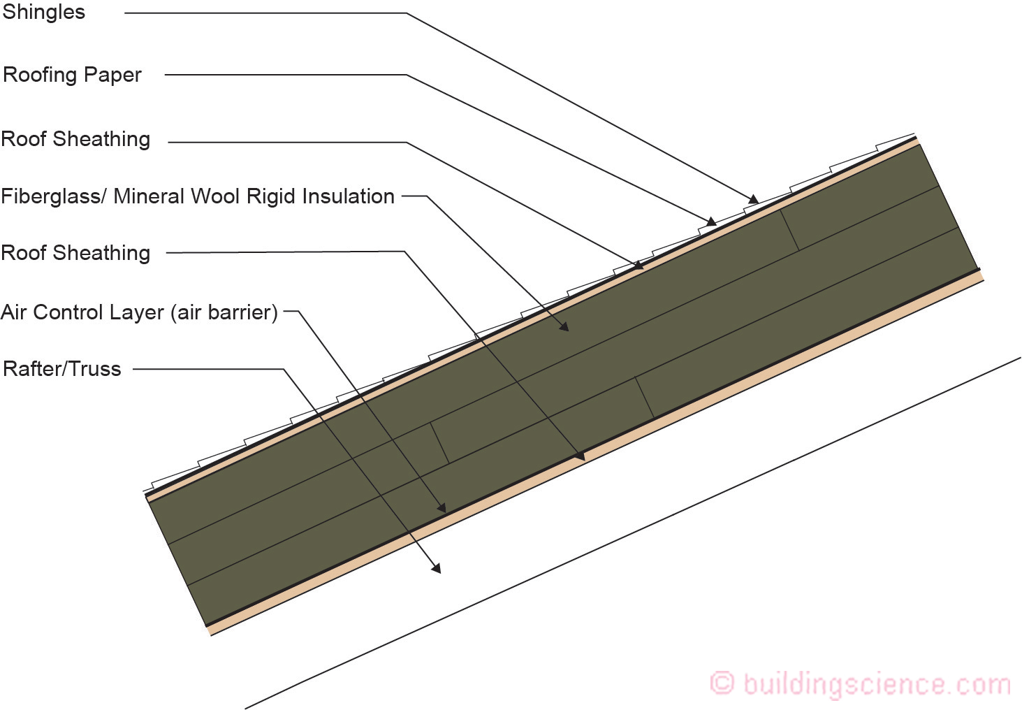
Figure 5: Controlling Condensation - The key to unvented attic and roof assemblies is to control condensation or moisture accumulation on the underside of the roof sheathing. One approach is to raise the temperature of the roof sheathing by insulating on the top of the roof sheathing.
If all of the insulation is on the top of the roof sheathing, it is clear that the temperature of the roof sheathing is raised sufficiently to control condensation and moisture accumulation. Insulation added on the top of a roof deck can be vapor impermeable or vapor permeable. All of the rigid insulation board products work, including mineral wool and rigid fiberglass.
There must be an air control layer (“air barrier”) under the rigid insulation boards. The air control layer can be a fully adhered membrane on the roof deck, or the air control layer can be the roof deck itself (airtight sheathing with taped or sealed seams). The rigid board insulation should be installed in multiple layers, with joints offset to limit three dimensional airflow networks within the multiple layers of this assembly.
It is not necessary to install all of the insulation on the top of the roof sheathing to elevate its temperature sufficiently to control condensation and moisture accumulation. Some insulation can be located above the top of the roof sheathing, and some of the insulation can be located on the underside of the roof sheathing (Figure 6). Sufficient insulation should be located above the roof sheathing to keep the moisture content of the sheathing below 20 percent by weight for the coldest part of the winter. Roof sheathing moisture content drops quite quickly in the spring. The roof sheathing moisture content should be below 16 percent for the summer and the fall. These moisture content limits have been shown to also address mold growth based on historical experience. How much insulation should be located above the roof sheathing depends on the climate zone and the interior moisture load. The model codes specify the amount of insulation necessary based on climate zone. The model codes assume an interior moisture load based on historical experience and test hut experimentation over several decades.
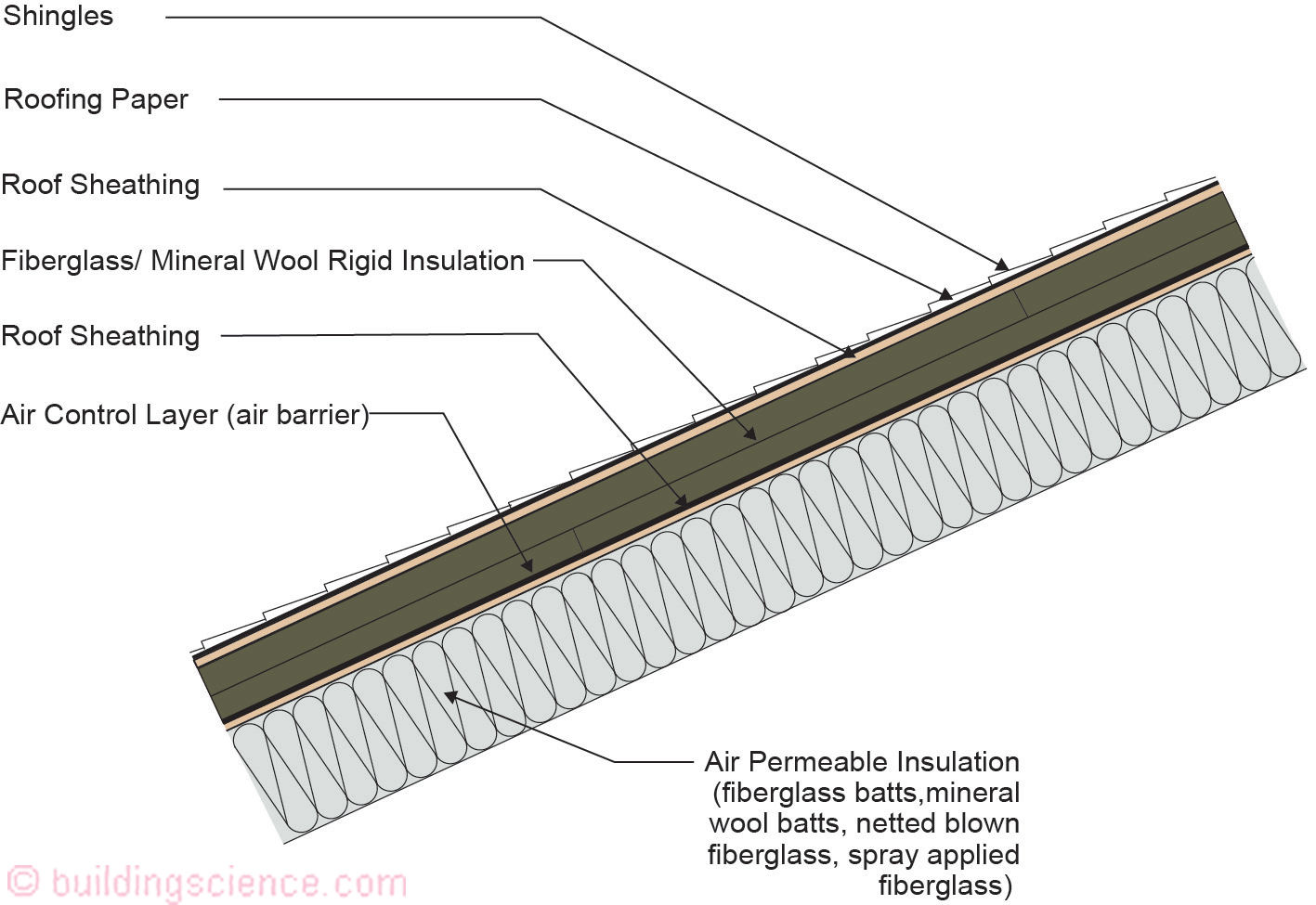
Figure 6: Controlling Condensation - It is not necessary to install all of the insulation on the top of the roof sheathing to elevate its temperature sufficiently to control condensation and moisture accumulation. Some insulation can be located above the top of the roof sheathing and some of the insulation can be located on the underside of the roof sheathing.
The model codes assume a residential occupancy – a moisture load of approximately 35 percent relative humidity at 68 degrees F in winter.
The model codes specify a specific performance requirement: the temperature of the roof sheathing should be maintained above 45 degrees F (7 degrees C). For calculation purposes an interior air temperature of 68 degrees F (20 degrees C) is assumed and the exterior air temperature is assumed to be the monthly average outside temperature of the three coldest months. This is an engineering equation providing boundary conditions derived from observed experimentation and field experience.
This is an “insulation ratio” – the R-value on the top of the roof sheathing compared to the R-value on the underside of the roof sheathing…and the ratio changes based on climate severity. The model codes specify the ratios based on climate zone (Table 1). Note how the ratio changes from approximately 10 percent to 70 percent, as the assembly moves from hot climates to cold climates.
Insulation for Condensation Control*
Climate Zone | Rigid Board or Air Impermeable Insulation | Code Required R-Value | Ratio of Rigid Board Insulation or Air Impermeable R-Value to Total Insulation R-Value |
1,2,3 | R-5 | R-38 | 10% |
4C | R-10 | R-49 | 20% |
4A, 4B | R-15 | R-49 | 30% |
5 | R-20 | R-49 | 40% |
6 | R-25 | R-49 | 50% |
7 | R-30 | R-49 | 60% |
8 | R-35 | R-49 | 70% |
Table 1: *Adapted from Table R 806.5 2015 International Residential Code
The key requirement is that the ratio of the thermal resistance of the exterior rigid insulation versus the thermal resistance of the interior fiberglass or mineral wool must comply with the “ratio” in Table 1.
Another way to control condensation or moisture accumulation on the underside of the roof sheathing is the “flow through” approach.
The “flow through” approach is limited to hot dry climates such as Las Vegas and Phoenix (Climate Zones 2B and 3B). The roof cladding needs to be “back-vented,” and the roof sheathing and roofing paper, roofing felt, or roofing membrane need to be vapor open. The most typical manifestation of this is a tile roof over batten strips over a roofing felt over plywood or OSB sheathing (Figure 7). Any moisture that accumulates on the underside of the roof sheathing (the “first” condensing surface) can pass through (“flow through”) the sheathing and the roofing felt, into the air gap under the tile roof, and be vented away. New materials allow the roofing paper or roofing felt to be replaced with a vapor permeable fully adhered membrane, or a semi vapor permeable taped OSB sheathing. Netted fiberglass, fiberglass batts, and mineral wool batts are common insulations that are used in the rafter cavities.
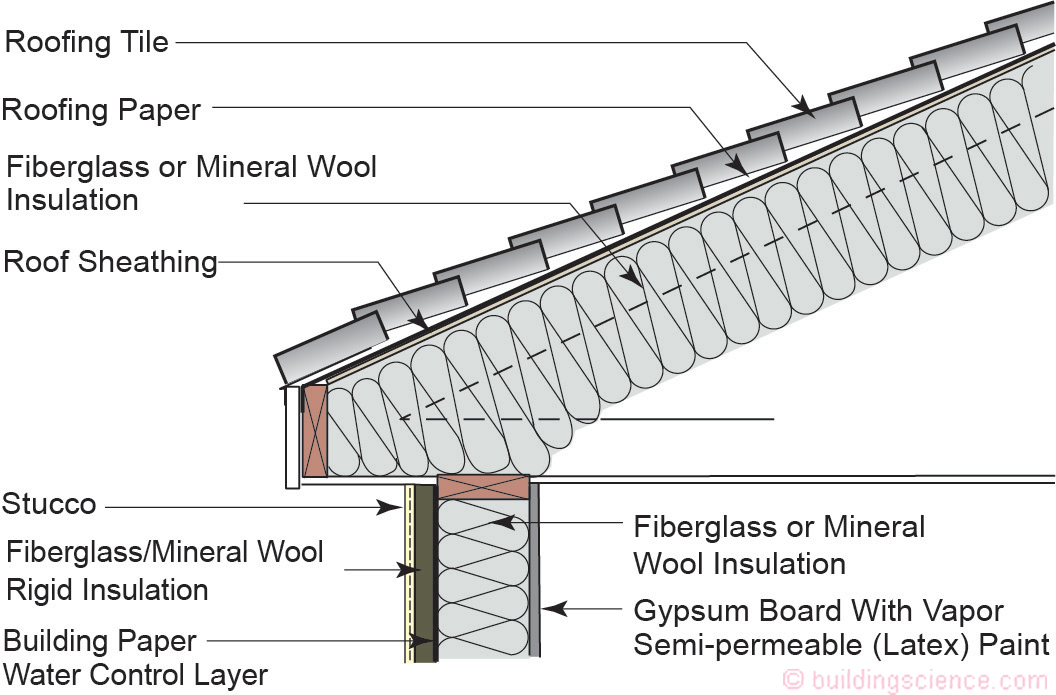
Figure 7: “Flow Through” Approach - The “flow through” approach is limited to hot dry climates such as Las Vegas and Phoenix. The roof cladding needs to be “back-vented,” and the roof sheathing and roofing paper/roofing felt/roofing membrane need to be vapor open. The most typical manifestation of this is a tile roof over batten strips over a roofing felt over plywood or OSB sheathing.
The final way to control condensation or moisture accumulation on the underside of the roof sheathing is to remove attic/roof assembly moisture via vapor diffusion rather than air change between the attic/roof assembly and the exterior.
When using fiberglass and mineral wool insulation to construct conditioned unvented attics or unconditioned unvented attics, moisture control is provided by letting water vapor exit the roof at the roof peak via a mechanism called vapor diffusion. A “vapor diffusion port” allows water vapor to exit—but prevents inward or outward airflow. The vapor diffusion port is “vapor open” but “air tight”. The vapor diffusion port is also “water tight,” preventing entry of rainwater. This mechanism works because air containing water vapor (“humid” air) is less dense and more buoyant than “dry” air. As such, the water vapor ends up at the peak or ridge of attics. When it gets there, the water vapor passes to the exterior, through a vapor permeable, but air and water tight layer.
There are limitations to this approach based on climate and roof slope. The approach is limited to hot-dry and hot-humid climates (IECC Climate Zones 1, 2 and 3). Additionally, the roof must be sloped to allow moisture buoyancy to work – the roof slope must be greater than or equal to 3:12 (vertical/horizontal).
In attic spaces and sloping rafter roof assemblies, one of the reasons moisture accumulates at the ridge is hygric buoyancy – the other is thermal buoyancy. Installing a “vapor diffusion vent or vapor diffusion port” at the upper part of attic spaces and sloping rafter roof assemblies allows this moisture (in the vapor phase) to exit the attic and roof assembly. In practice, this involves eliminating the lower soffit attic/roof vents, while installing standard roof vents near the ridge, but covering the vent opening in the roof deck with an airtight but vapor open layer (Figure 8, Figure 9, Figure 10 and Figure 11). 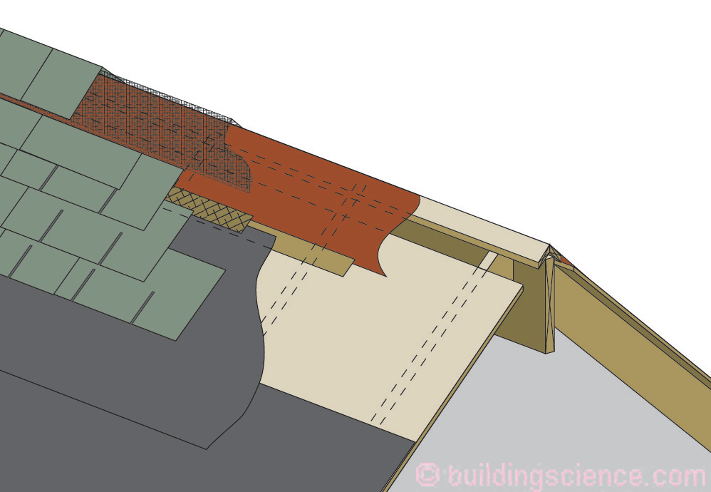
Figure 8: Vapor Diffusion Port (Strip Port Openings) Shingle Roofs – Standard roof vents located at the ridge, but with the opening in the roof deck covered with an airtight but vapor open layer.
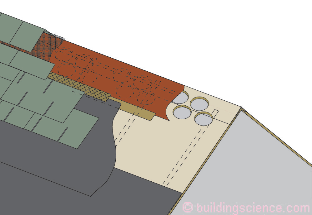
Figure 9: Vapor Diffusion Port (Round Port Openings) Shingle Roofs – Holes near ridge through sheathing to maintain structural diaphragm, covered with an airtight but vapor open layer.
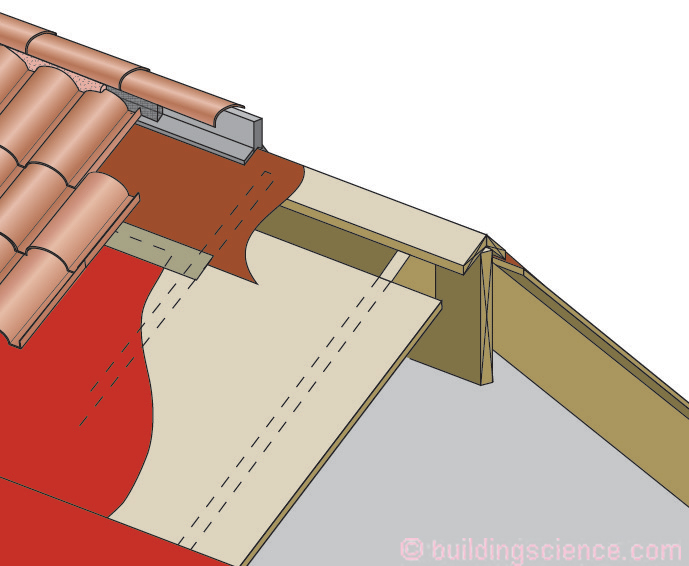
Figure 10: Vapor Diffusion Port (Strip Port Openings) Tile Roofs - Standard roof vents located at the ridge but with the opening in the roof deck covered with an airtight but vapor open layer.
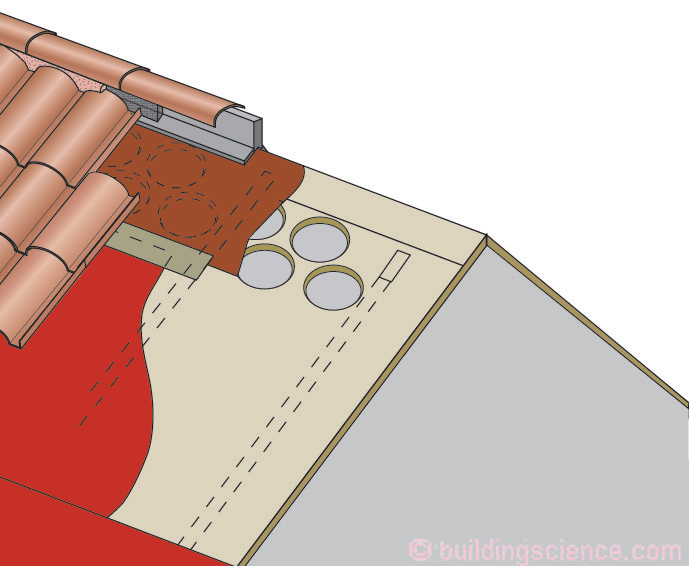
Figure 11: Vapor Diffusion Port (Round Port Openings) Tile Roofs - Holes near ridge through sheathing to maintain structural diaphragm, covered with an airtight but vapor open layer.
Two types of vapor diffusion port openings are typical – strip port openings and round port openings – depending on structural requirements. Strip port openings are analogous to the omitted sheathing used in typical vented roof ridge vents. However, standard ridge vent openings can compromise roof deck diaphragm (“shear”) resistance. Using round openings in roof sheathing addresses this issue. Round openings are typically used at roof hip assemblies to maintain the roof deck structural diaphragm. A standard roof vent is extended downward along the hip 2 to 3 feet (Figure 12). Similar approaches are used for dormer roofs.
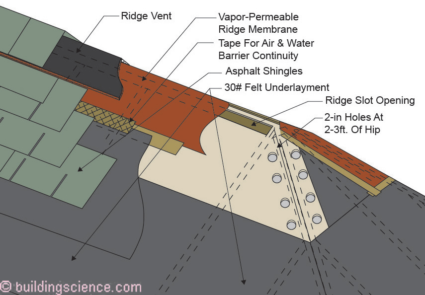
Figure 12: Hip Roof Assemblies - Round openings are typically used at roof hip assemblies to maintain the roof deck structural diaphragm. Standard roof vent extended downward along the hip 2 to 3 feet.
The diffusion port approach is limited to IECC Climate Zones 1, 2 and 3. It should not be used in colder climate zones.
The vapor permeance of the diffusion port covering should be greater than 20 perms. The ridge vent area should be approximately 1:150 of the ceiling area and the roof needs to be sloped a minimum of 3:12 or greater.
Where the insulation is installed on the underside of the roof deck and the insulation is “air permeable,” then HVAC supply air should be provided to the attic space from the interior of the house to remove moisture, by providing “conditioning” to the attic space, thereby treating it similar to a room or occupied space. At least 50 cfm for each 1,000 ft2 of ceiling area is required. This airflow does not need to be continuous. The typical 30 percent duty cycle of air conditioning system operation has been found to be effective. Alternatively, a dehumidifier can be installed.
Unconditioned Unvented Attics
In hot-humid climates, an increasingly common problem in vented attics is condensation (“sweating”) on attic ductwork and mold growth on attic sheathing and framing members. In addition, “burying” ductwork under attic insulation can greatly improve thermal performance, but has the potential to create moisture risks if implemented incorrectly. One approach to controlling ductwork sweating and burying standard ductwork and boots (insulated to less than R-13 in IECC Climate Zones 1A, 2A, 3A) is to seal (or not install) soffit vents, and to install a “vapor diffusion vent or vapor diffusion port” at the upper part of attic spaces and sloping rafter roof assemblies (Figure 2) and yes we were here before (“BSI-094: No Sweat”, April 2016). Doing this we get “unconditioned unvented attics”. Yup, add a new phrase to the vocabulary.
Danger! Danger! [2]
Because there is so much condensation occurring on ductwork in vented attics in hot humid climates folks are retrofitting the attics to be unvented. When both constructing conditioned unvented attics and unconditioned unvented attics and retrofitting attics to become conditioned unvented attics and unconditioned unvented attics, it is critical that only sealed combustion appliances such as gas furnaces and gas water heaters are installed in such unvented attics. Let me repeat this a little differently…if you are stupid you can die. Please don’t be stupid.
Footnotes
[1] Not modeling….you use real world stuff to “tune” models. You do not believe models until you build the “modeled thingy” and measure how it works…in the real world. Then you believe the model. Most models ought to be quarantined with their modelers.
[2] Phrase uttered by Robot B9 from the TV series “Lost in Space” when someone is about to do something stupid…Robot B9 is not to be confused with Robby the Robot from the movie Forbidden Planet. Robby the Robot came to life in 1955…the same year I did…Robot B9 was on television in 1967…the last year the Toronto Maple Leafs won the Stanley Cup…
References
Lstiburek, J.W.; Venting vapor, ASHRAE Journal, July 2015.
https://www.buildingscience.com/documents/insights/bsi-088-venting-vapor
Lstiburek, J.W.; No sweat, ASHRAE Journal, April 2016.
https://www.buildingscience.com/documents/building-science-insights-newsletters/bsi-094-no-sweat
Lstiburek, J.W.; Hybrid assemblies, ASHRAE Journal, October 2017.
https://www.buildingscience.com/documents/building-science-insights/bsi-100-hybrid-assemblies
Ueno, K and Lstiburek, J.W.; Building America Report: Field testing of an unvented roof with fibrous insulaiton, tiles, and vapor diffusion venting, Building Science Corporation, November 2015.
Ueno, K and Lstiburek, J.W.; Building America Report: Field testing of unvented roofs with asphalt shingles in cold and hot-humid climates, Building Science Corporation, June 2015.
Ueno, K and Lstiburek, J.W.; Monitoring of two unvented roofs with air-permeable insulation in Climate Zone 2A; Thermal Performance of the Exterior Envelopes of Whole Buildings XIII International Conference, Clearwater, FL, December, 2016.