A building is an environmental separator. In fundamental terms its function is to “keep the outside out” and the “inside in”. The outside provides “environmental loads” as does the inside. When rehabilitating existing buildings these loads can be addressed from either the inside or outside or both sides. When an existing building has historic significance or when it is “aesthetically attractive” addressing the environmental loads is typically limited to the interior. There are exceptions where the exterior “intervention” is limited or for all practical purposes “invisible” or “subtle” or “stealthy”.
Mass masonry walls manage moisture in different ways than modern, drained assemblies. Therefore, the balance of moisture (into and out of the wall) is strongly affected by interior insulation as the wall becomes colder. The assembly has reduced drying (because the energy flow through the wall has been reduced), and less drying to the interior (due to the addition of vapor-impermeable layers on the interior). In addition, moisture flow caused by air leakage into the interface between the masonry and the insulation can result in condensation problems; therefore, excellent airtightness is critical. The primary concern with insulating older load bearing masonry buildings in cold climates is the possibility of freeze-thaw damage of the brickwork and decay in any embedded wood structure. Both concerns are related to excess moisture content.
Keeping the mass assembly from getting excessively wet from the exterior is important. We have been here before (“BSI-095: How Buildings Age?”, May 2016). Invisible, subtle and stealthy exterior “rain management” is necessary to preserve the historic nature of the façade.
Keeping the mass assembly from getting excessively wet from the interior is also important. The first step is to keep the interior moisture load low. For mass buildings, interiors are assumed to be conditioned to around 70°F in the winter and 75°F in the summer. Unlike new construction, in Climate Zones 5 and higher, interior relative humidity in mass buildings should be limited to 30 percent (no higher) during the coldest month in winter.
Load-bearing masonry walls pose a condensation risk at the masonry-to-insulation interface. Air leakage could bypass imperfectly installed air barriers, resulting in condensation problems. To avoid this problem, excellent airtightness on the interior is essential. Options for retrofitting an air barrier at a mass masonry wall include the application of a liquid- applied or membrane and sheet good air barriers on the interior side, or the use of an insulation material that creates an air barrier.
The mass walls to be retrofitted could include both multi-wythe solid brick walls, and exterior brick with a hollow clay block infill/backup wall. The interior of mass walls may be finished with plaster, often gypsum or lime-cement based, and sometimes installed over furring strips and/or lath. In some cases, a layer of bitumen is applied between the interior finish and the masonry. It is necessary to remove any existing interior furring, lath and plaster to expose the brick structure from the interior for retrofit since they could be moisture sensitive (like gypsum), or form a void that can create unintentional air leakage (such as furring and lath). Photograph 1, Photograph 2, Photograph 3 and Photograph 4 show conditions after removal/demolition of the interior furring, lath, and plaster. No one said this was going to be easy.
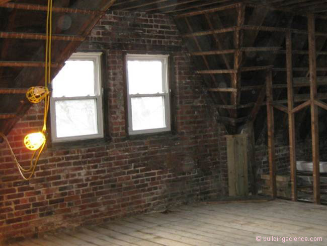
Photograph 1 – Solid Brick: Excellent condition. No large void areas.
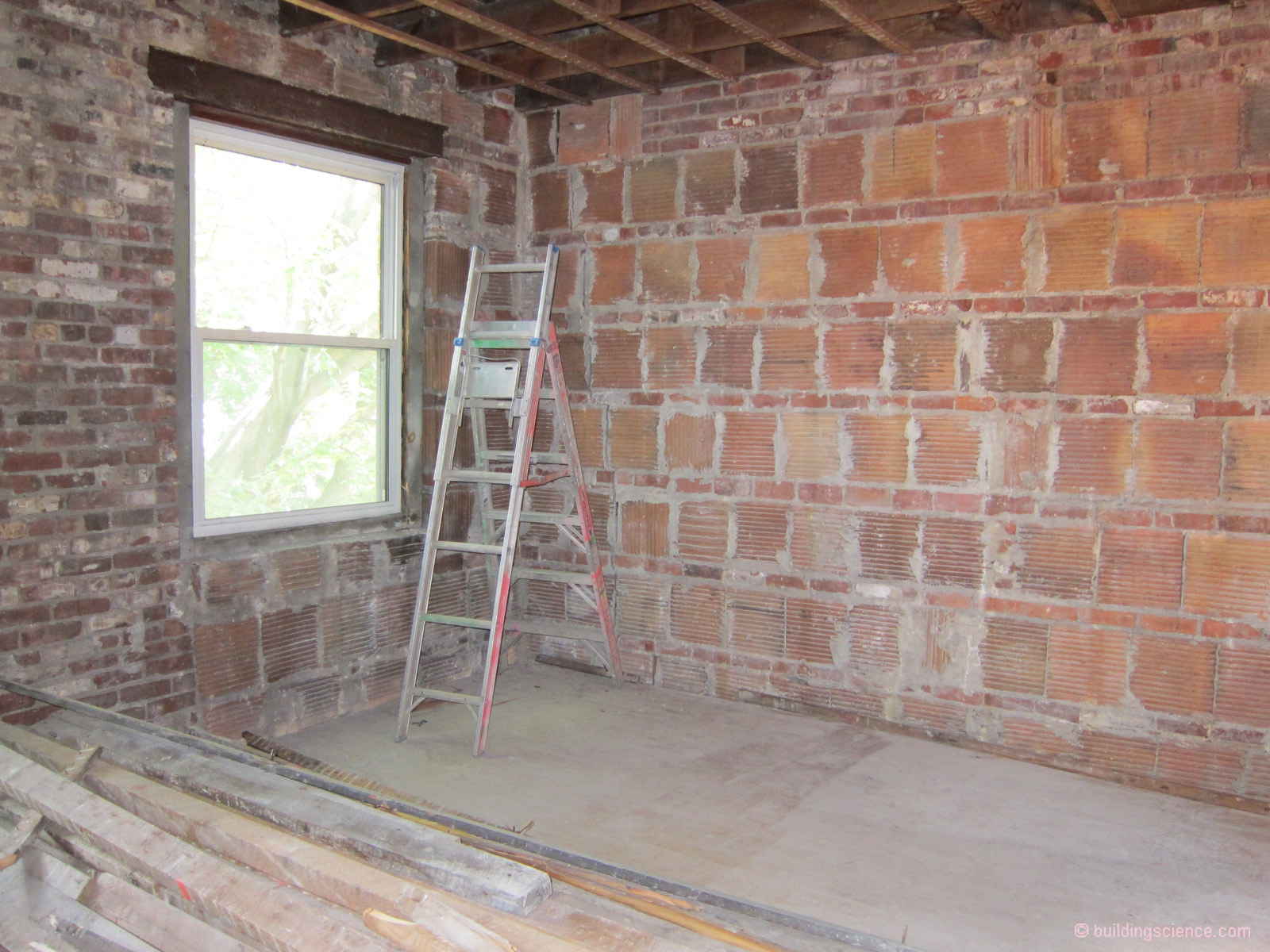
Photograph 2 – Clay Tile: Excellent condition. No large void areas.
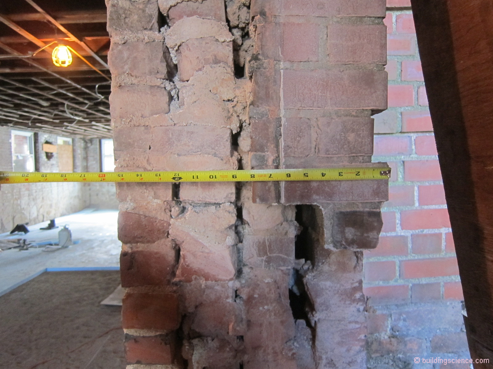
Photograph 3 – Brick Wall Section: Solid mass walls are not typically solid. Let me repeat…solid mass walls are not typically solid.
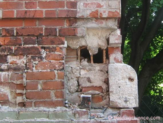
Photograph 4 – Clay Tiles: Clay tiles are hollow. Did I mention that solid mass walls are not typically solid?
The enclosure is not the only thing that needs to be addressed. So must the space conditioning system and ventilation system. All and any atmospherically vented (or naturally aspirated) combustion appliance needs to be replaced with direct-vented or direct exhaust-vented equipment.
Kitchen and bathroom exhaust fans should be vented to the exterior of the building…and added if they do not exist at all. Controlled mechanical ventilation needs to be added (we have been here before as well… "BSI-075: How Buildings Stack Up”, February 2014).
The following approaches can be used in the noted climate zones to insulate mass assemblies on the interior and stay out of trouble….with the following caveats…you need to keep the rainwater from excessively wetting the exterior and you need to keep the interior relative humidity low during the winter months in Climate Zones 5 and higher…
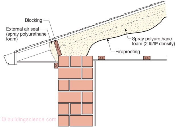
Roof Approach One
Flat roof with parapet insulated from underneath with with spray polyurethane foam (2 lb/ft3 density) installed directly to the underside of the roof sheathing (Figure 1). Spray applied fire proofing is applied to the spray foam. Note the added parapet exterior drip edges.
This approach works in all climate zones.

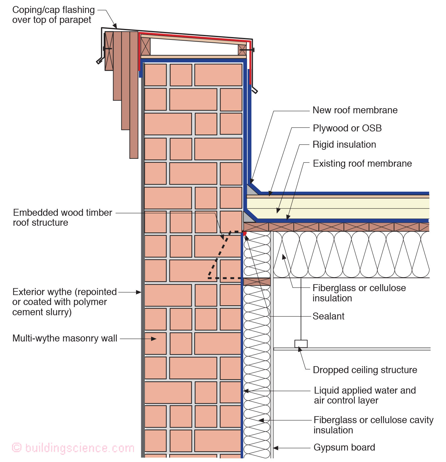
Roof Approach Two
Flat roof with parapet insulated from above with rigid insulation and from underneath with fiberglass or cellulose or rockwool/mineral wool insulation (Figure 2). Note the added parapet exterior drip edges.
This approach works in all climate zones – when the ratio of insulation above the roof deck compared to ratio of insulation below the roof deck is correct (again we have been here before…see “BSI-100: Hybrid Assemblies”, October 2017).
Roof Approach Three
Vented attic with air sealed ceiling penetrations (Figure 3).
Blown cellulose or fiberglass or rockwool or mineral wool insulation .
This approach works in all climate zones.
Roof Approach Four
Conditioned attic with spray polyurethane foam (2 lb/ft3 density) installed directly to the underside of the roof sheathing (Figure 4). Spray applied fire proofing is applied to the underside of the spray polyurethane foam.
This approach works in all climate zones.
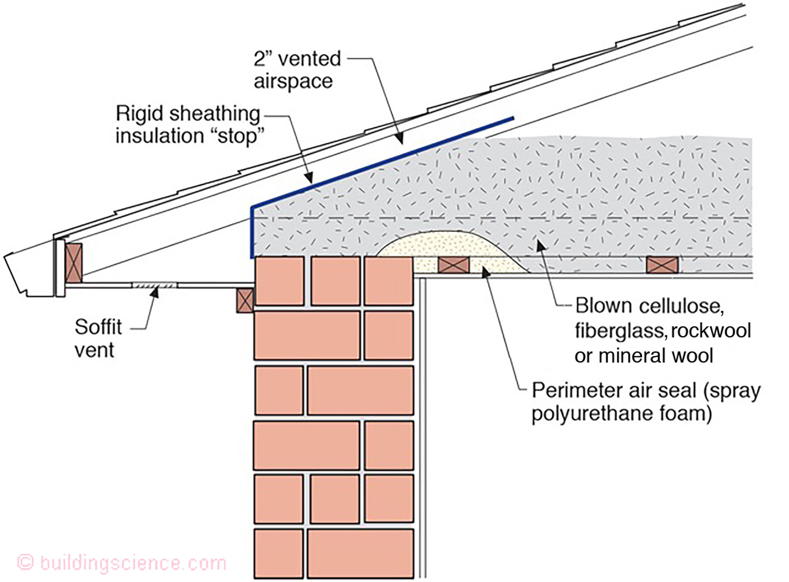
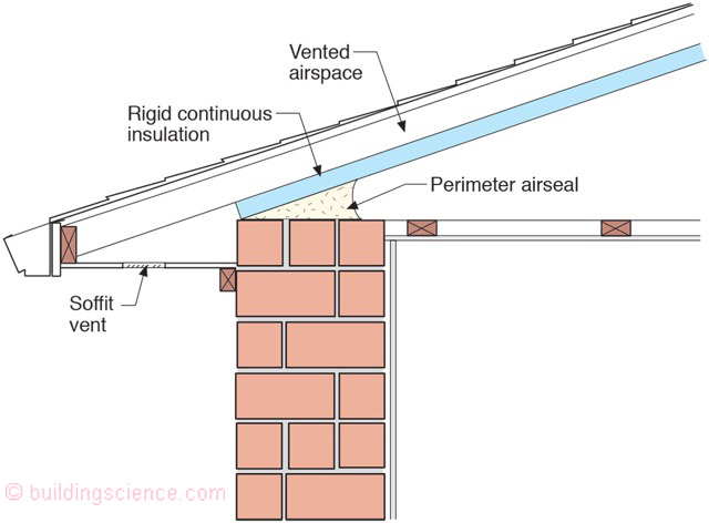
Roof Approach Five
Cathedralized conditioned attic with rigid continuous insulation installed directly to the underside of rafter framing. The rafter cavity is vented (Figure 5).
This approach works in all climate zones.
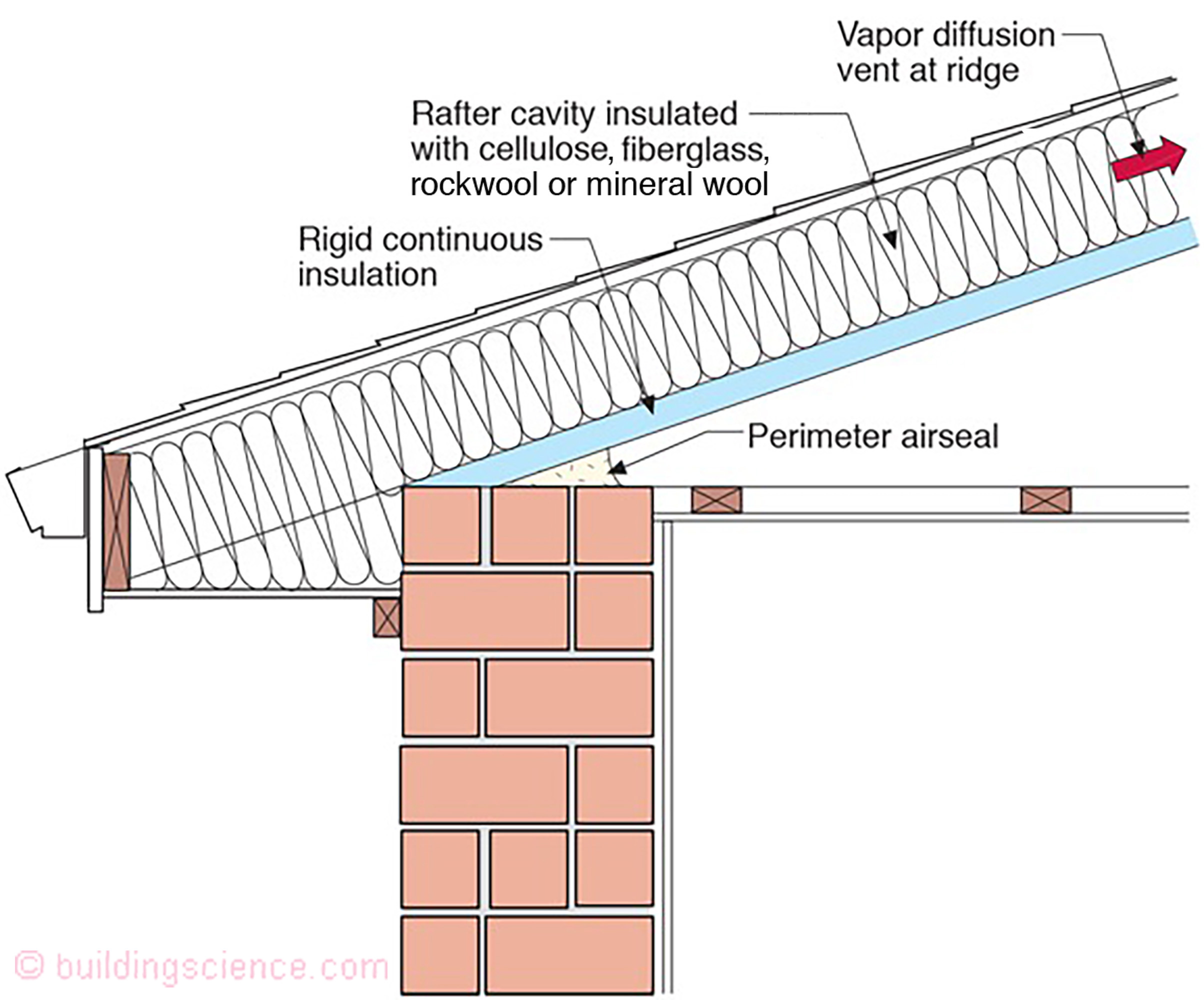
Roof Approach Six
Cathedralized conditioned attic with rigid continuous insulation installed directly to the underside of rafter framing. The rafter cavity is insulated with cellulose or fiberglass insulation (Figure 6). A vapor diffusion ridge vent is located at the ridge only. Soffit venting is not required.
This approach works in all climate zones.
Wall Approach One
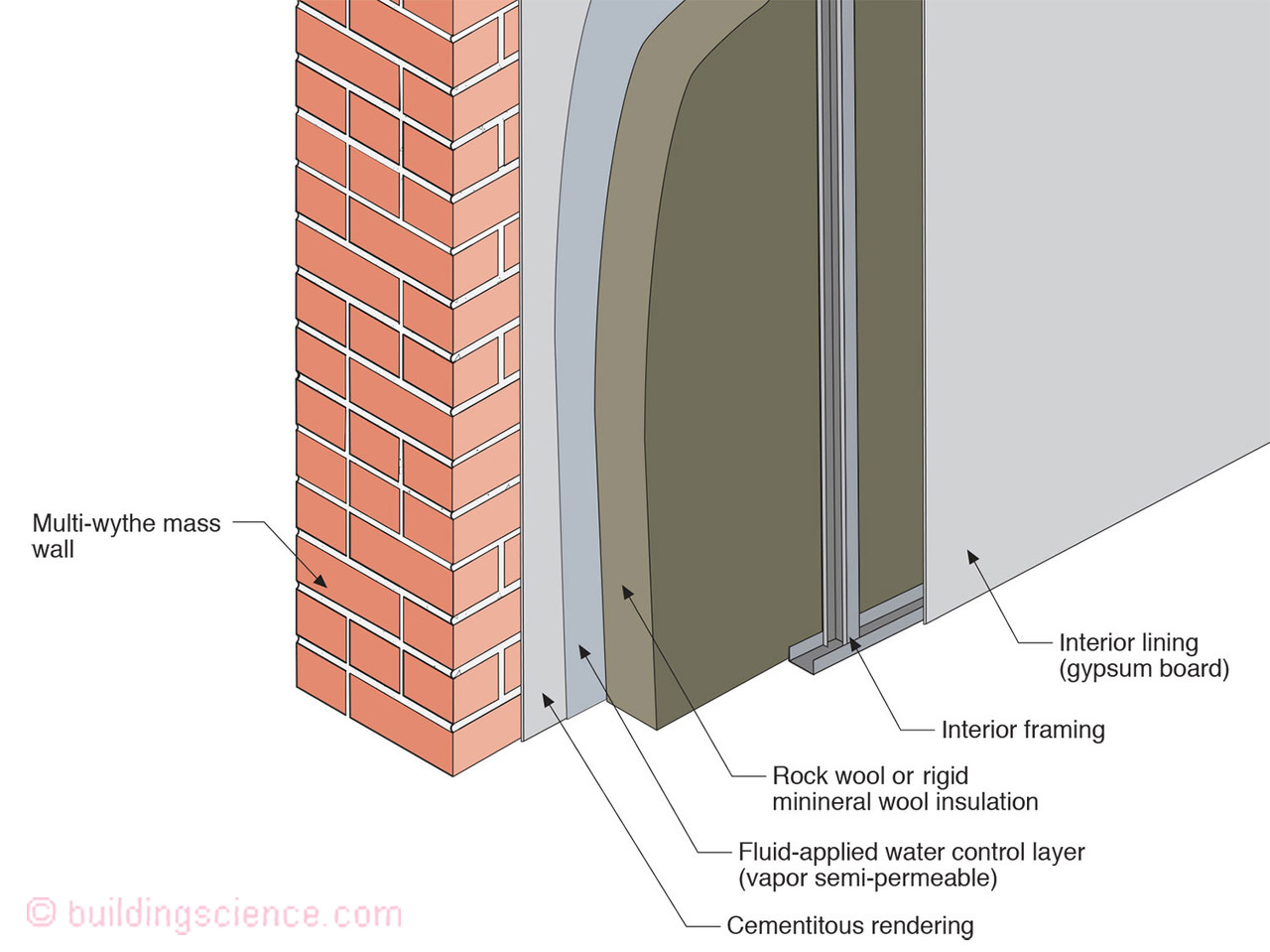
Cementitious parge coat (“rendering”) on the interior of a mass wall assembly (multi-wythe brick or block or clay tile) (Figure 7).
Fluid applied water control layer (vapor semi-permeable) on the cementitious rendering.
Spray applied polyurethane foam (2 lb/ft3 density).
Interior framing (wood studs or metal studs) creating service cavity.
Interior lining (gypsum wall board and interior finish).
This approach works in all climates with the following limitation – in zones where freeze-thaw damage is a risk – exterior rain water control (“rain shedding”) must also be employed.

Wall Approach Two
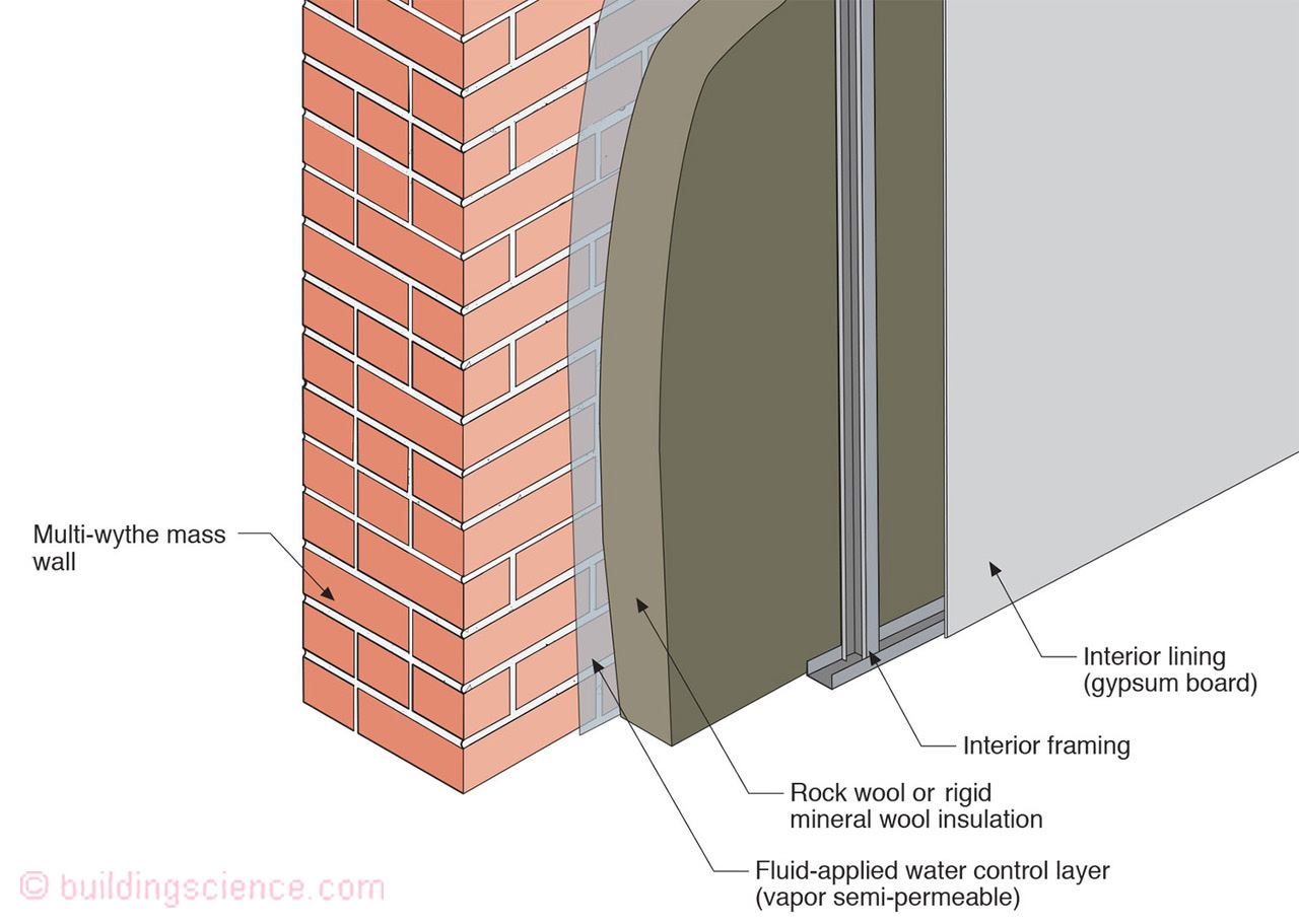
Fluid applied water control layer (vapor semi-permeable) on the interior of a mass wall assembly (multi-wythe brick or block or clay tile) (Figure 8).
Spray applied polyurethane foam (2 lb/ft3 density).
Interior framing (wood studs or metal studs) creating service cavity.
Interior lining (gypsum wall board and interior finish).
The only alteration from Wall Approach One is the removal of the cementitious parge coat. The use of the parge coat is dependent on the “smoothness” of the interior mass wall surface. Rough interior textures may not be able to be coated effectively with a fluid applied water control layer. This approach works in all climates with the following limitation – in zones where freeze-thaw damage is a risk – exterior rain water control (“rain shedding”) must also be employed.

Wall Approach Three
Cementitious parge coat (“rendering”) on the interior of a mass wall assembly (multi-wythe brick or block or clay tile) (Figure 9).
Fluid applied water control layer (vapor semi-permeable) on the cementitious rendering.
Rigid mineral wool board sheathing.
Interior framing (wood studs or metal studs) creating service cavity.
Interior lining (gypsum wall board and interior finish).
The alteration from Wall Approach One is the use of rigid mineral wool board sheathing in place of spray polyurethane foam. This approach works in climate zones 4 or lower.
Wall Approach Four
Fluid applied water control layer (vapor semi-permeable) on the interior of a mass wall assembly (multi-wythe brick or block or clay tile) (Figure 10).
Rigid mineral wool board sheathing.
Interior framing (wood studs or metal studs) creating service cavity.
Interior lining (gypsum wall board and interior finish).
The alteration from Wall Approach One is the removal of the cementitious parge coat and the use of rigid mineral wool board sheathing in place of spray polyurethane foam. This approach works in climate zones 4 or lower.
Wall Approach Five
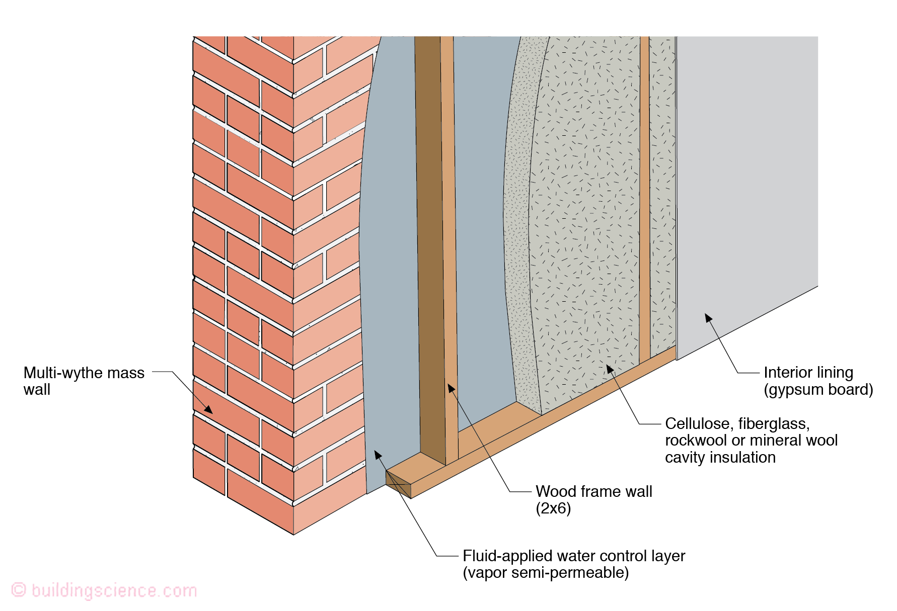
Fluid applied water control layer (vapor semi-permeable) on the interior of a mass wall assembly (multi-wythe brick or block or clay tile) (Figure 11).
Interior framing (wood frame wall – 2x4 or thicker).
Cellulose or fiberglass cavity insulation.
Interior lining (gypsum wall board and interior finish).
The alteration from Wall Approach One is the removal of the cementitious parge coat and the use of cellulose or fiberglass cavity insulation in place of spray polyurethane foam and the use of an interior wood frame wall. This approach works in climate zones 4 or lower.
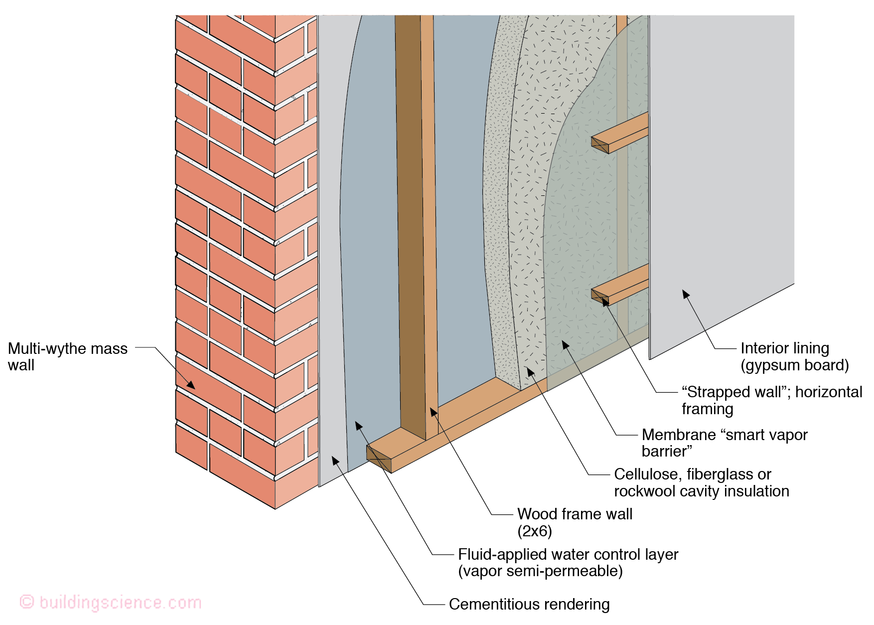
Wall Approach Six
Cementitious parge coat (“rendering”) on the interior of a mass wall assembly (multi-wythe brick or block or clay tile) (Figure 12).
Fluid applied water control layer (vapor semi-permeable) on the cementious rendering.
Wood frame wall (2x4 or 2x6) insulated with cellulose cavity insulation.
Membrane “smart vapor barrier” installed on the interior of the frame wall.
Second layer of interior framing (“strapped wall”) creating service cavity.
Interior lining (gypsum wall board and interior finish).
This approach works in all climates with the following limitation – in zones where freeze-thaw damage is a risk – exterior rain water control (“rain shedding”) must also be employed.
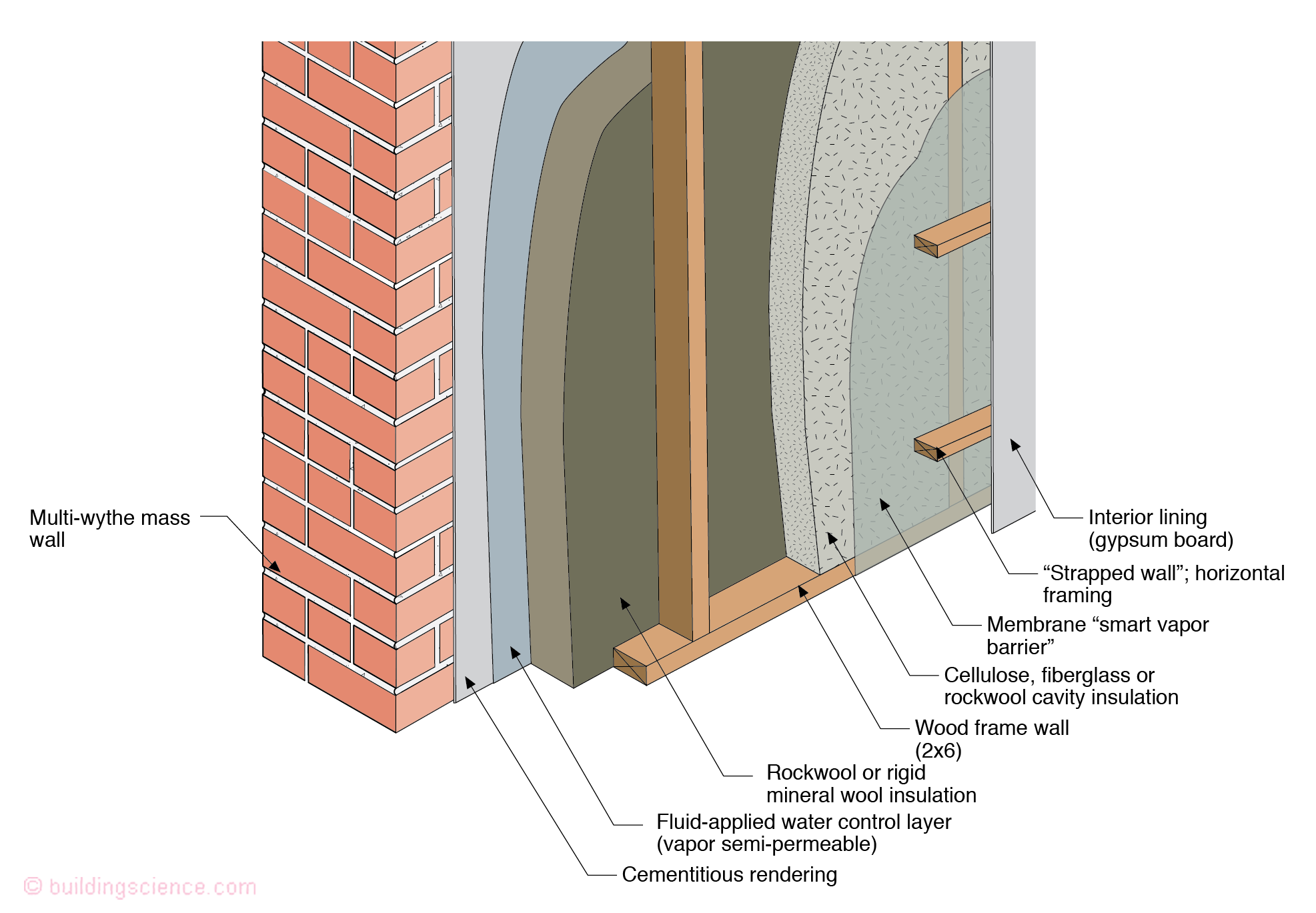
Wall Approach Seven
Fluid applied water control layer (vapor semi-permeable) on the interior of a mass wall assembly (multi-wythe brick or block or clay tile) (Figure 13).
Rigid mineral wool board sheathing.
Wood frame wall (2x4 or 2x6) insulated with cellulose or fiberglass or rockwool cavity insulation.
Membrane “smart vapor barrier” installed on the interior of the frame wall.
Second layer of interior framing (“strapped wall”) creating service cavity.
Interior lining (gypsum wall board and interior finish).
This approach works in all climate zones.
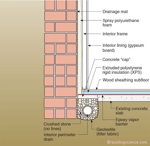
Foundation Approach One
Figure 14.
Interior perimeter drain.
Interior drainage mat.
Spray applied polyurethane foam (2 lb/ft3 density).
Interior framing (wood studs or metal studs) creating service cavity.
Interior lining (gypsum wall board and interior finish).
This approach works in all climates with only the following limitation – where embedded floor joists are utilized sufficient diffusion drying surface area above grade to the exterior must exist to limit the moisture content of the embedded floor joists.
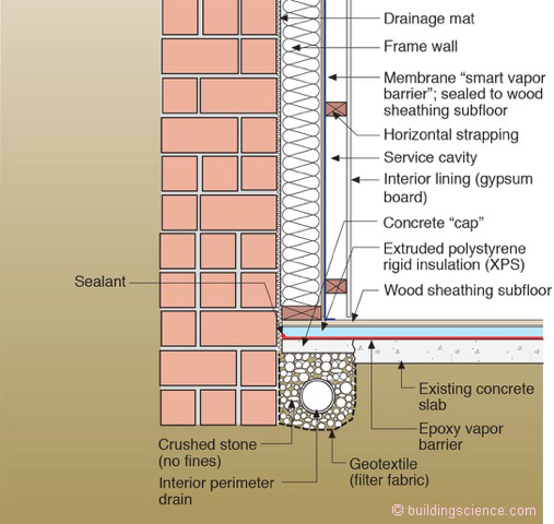
Foundation Approach Two
Figure 15.
Interior perimeter drain.
Interior drainage mat.
Wood frame wall (2x4) insulated with cellulose cavity insulation.
Membrane “smart vapor barrier” installed on the interior of the frame wall.
Second layer of interior framing (“strapped wall”) creating service cavity.
Interior lining (gypsum wall board and interior finish).
This approach works in all climates with only the following limitation – where embedded floor joists are utilized sufficient diffusion drying surface area above grade to the exterior must exist to limit the moisture content of the embedded floor joists.
Foundation Approach Three
Figure 16.
Interior perimeter drain.
Interior drainage mat.
Wood frame wall (2x4) insulated with cellulose cavity insulation.
Interior lining (gypsum wall board and interior finish).
This approach works in climate zones 4 or lower with only the following limitation – where embedded floor joists are utilized sufficient diffusion drying surface area above grade to the exterior must exist to limit the moisture content of the embedded floor joists.
