Maybe not. For years I have said that dog won’t hunt1. I have come around. The engineer in me likes tools. I can’t help it – it is a genetic defect we engineers are born with. With therapy we engineers have learned that tools come with limitations – Clint Eastwood comes to mind2. I think WUFI has turned into a useful modeling tool and is getting progressively more useful. I never thought I would ever write those words.
WUFI is the brainchild of Hartwig Kunzel aka “The Konig of WUFI” from the Fraunhofer Institute for Building Physics and is a software tool for calculating coupled heat and moisture transfer in building assemblies. It has gone through two decades of refinements. I think its time has come. For the record I have always said the problem has never been the model – but the modeler. A tool is only as useful as the skill of the person using the tool3.
The physics has proved to be daunting. We know how to model heat flow and have known so for a long time. Moisture flow? Not so much. The problem, among other things, is that water exists in four phases: vapor, liquid, solid and adsorbate. And these phases interact with each other in ways that are not clearly understood (Figure 1). There is no accepted theory of combined heat and moisture flow. Let me repeat: there is no accepted theory of combined heat and moisture flow. As such the interactions in models—not just WUFI—are currently phenomenologically-based. We engineers build it, wet it and watch what happens. Analysis is observation and experience based. We are still waiting for the physicists to figure out the theory4. In the meanwhile we have got things to design and build.
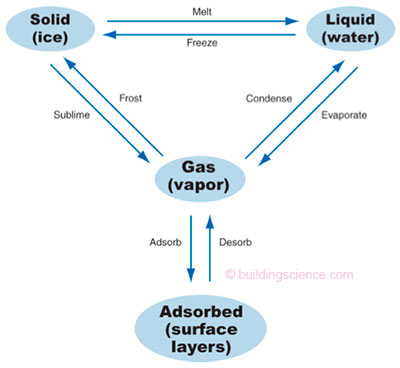
Figure 1: Phases of Water—Water exists in four phases: vapor, liquid, solid and adsorbed.
These phases interact as shown.
We guess – educated guesses – but guesses never-the-less. And we simplify. We take Figure 1 and we apply it to a porous material. We get the transport processes and driving potentials in Table 1. WUFI ignores osmosis. Why? You're kidding righ? Well, because including osmosis interactions makes things way too complicated. Go back and check out “BSI-047: Thick as a Brick” and “BSI-045: Double Rubble Toil and Trouble”. Why porous materials? Non-porous materials are easy to figure out. You don’t need a model for them. They don’t absorb moisture. They don’t get wet – except on the surface. Easy.
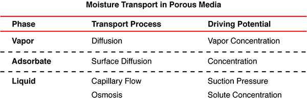
Table 1: Moisture Transport in Porous Media—We take Figure 1 and apply it to a porous material. We get the listed transport processes and driving potentials.
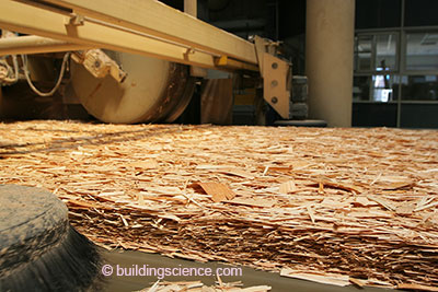
Now what? We need to figure out how model the transport processes and driving potentials in Table 1 (less osmosis). Remember we don’t have theory to work with. Well, we start by wetting a porous material and see what happens (Photograph 1)? Get a good watch. And spend some quality time – about a decade – and play with some gamma rays. And oh, by the way work with a bunch of smart folks and share5. Once you figure it out it gets easy (Photograph 2). Well, not really. It took years to figure it out more or less in a single material (Figure 2). It took the Konig and his colleagues in Germany more years to figure it out when several different materials were in direct contact with one another (Figure 3).
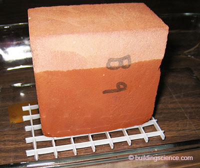
Photograph 1: Wetting “Take 1”—Wetting a porous material to see what happens. Get a good watch.
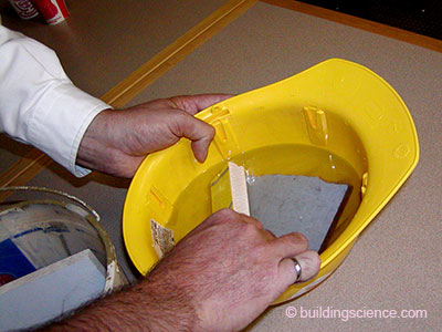
Photograph 2: Wetting “Take 2”—How an old guy does it.
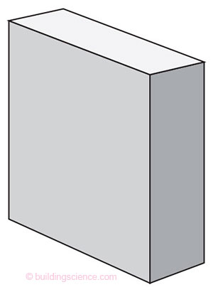
Figure 2: Single Material—Addressing the dynamic interactions in a single material is challenging on its own.

Figure 3: Several Materials in Contact—Addressing the dynamic interactions in several materials simultaneously proved to be an order of magnitude more difficult. Where the materials are in contact with each other, one-dimensional combined heat and moisture flow models provide reasonable correlation with real world examples and measurements.
But when the materials were not in direct contact with each other the models tended to break down (Figure 4). Again, all the models – not just WUFI. The problem was airflow. Airflow is a three-dimensional phenomenon. The models were one-dimensional. Oops. This was not a big issue with the Germans. Huh? Well, the Germans are Europeans – although they are currently having some heartburn with the European thing – and European building assemblies historically tend to be solid mass systems with little or no convective airflow. As such one-dimensional combined heat and moisture flow models – that ignored airflow—the early versions of WUFI—proved useful in analyzing performance and predicting performance – in European assemblies.
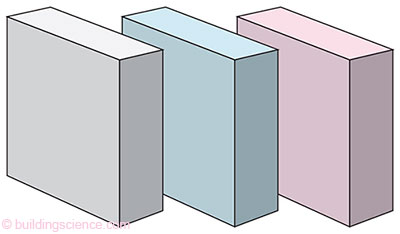
Figure 4: Several Materials not in Contact (Air Gap)—Where the materials are not in contact with each other one-dimensional models tend to break down as they are ill-equipped to handle airflow and the resultant convective flow.
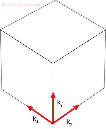
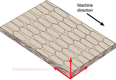
Figure 5 (above left): Material and Transport Properties Based on Orientation
Figure 6: Oriented Strand Board (above right)—OSB material and transport properties are orientation based.
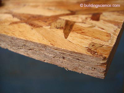
Photograph 3: Oriented Strand Board “Take 1” (above left)—Note the layered mats of aligned strands prior to heat and pressure.
Photograph 4: Oriented Strand Board “Take 2” (above right)—Finished product – an engineered “structural use panel.
Add a half-decade to figure out how to “fool” a one-dimensional model into giving reasonable results with materials that have orientation based properties and you get us to the two current remaining problems. The airflow piece we have already mentioned – and we will get back to it. But we have not yet talked about rainfall – the second of the remaining problems.
Both European and North America building assemblies are exposed to rain – this of course is obvious. That rain is a significant moisture load is also obvious. As such this moisture transport mechanism needs to be considered by hygrothermal models for the models to be useful. Modeling the rain transport mechanism – a three dimensional phenomena in a multi-layer system adds significant complexity.
We needed a “hoser” of German ancestry for this one6. And then some guesses and judgment. The key question to answer is how much rainwater hits the wall. A simple question, but not one that is simple to answer. WUFI software adapts the rainwater exposure models developed by Straube to determine the amount of rainwater that impinges on the wall. Some of this rainwater bounces off the wall. Some of this rainwater penetrates the cladding and finally some of this rainwater penetrates the water control layer. This is summarized in Figure 7.
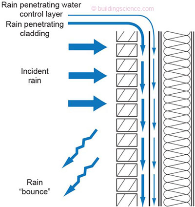
Figure 7: Rainwater Penetration in a Wall—Some of the rainwater bounces off the wall. Some of the rainwater penetrates the cladding and finally some of the rainwater penetrates the water control layer.
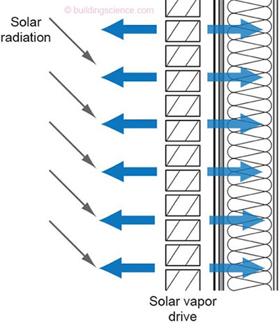
Figure 8: Solar Radiation on a Wall—The retained water is affected by the amount of solar radiation incident on the wall. We all know that solar radiation affects the liquid conductivity and vapor diffusion – except when we forget. Anyway, it should be obvious that model orientation plays a significant role.
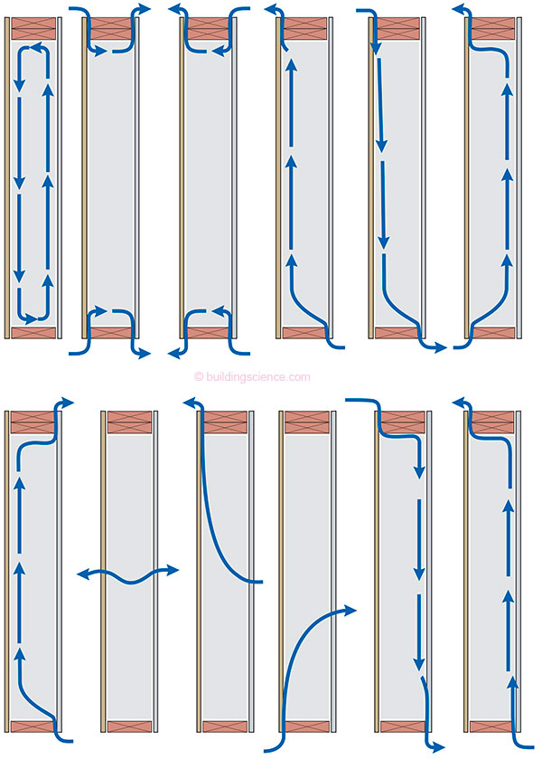
Figure 9: Airflow Mechanisms in a Wall—There are twelve (12) typical airflow pathways that need to be considered in multi-layer systems. The challenge is to model a complex three-dimensional phenomenon in a one-dimensional model.
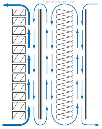
Figure 10: Combined Airflow Pathways (full level of complexity)—The airflow pathways arguably can be combined for modeling purposes as shown. Note the cladding ventilation component that has been added.
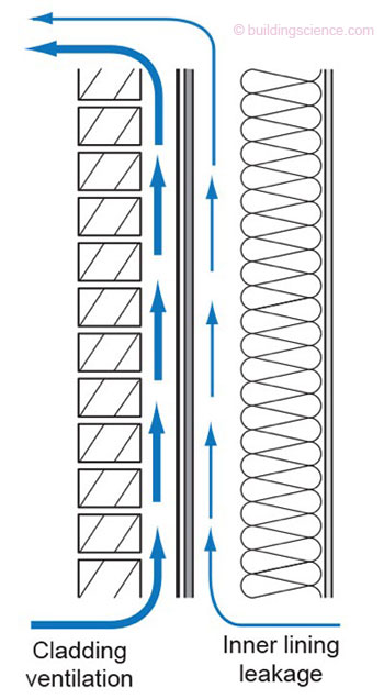
Figure 11: Further Simplification of Airflow Pathways—
The operative phrase is “further simplification of airflow pathways”.
In 2003, probably in a Bavarian beer garden, and after getting a letter from the “hoser” of German ancestry the Konig acknowledged the existence of North America and its particularly bizarre multi-layer airflow dominated method of assembly construction. The “hoser” recommended a “source” and “sink” method to approximate the effect of cladding ventilation and moisture transport. Within a year WUFI software became capable of modeling cladding ventilation. Jawohl, endich ist das Tor fur unsere Mannschaft gefallen!9
With this airflow element added WUFI allows us to approximate the flows in Figure 11 as shown in Figure 12.
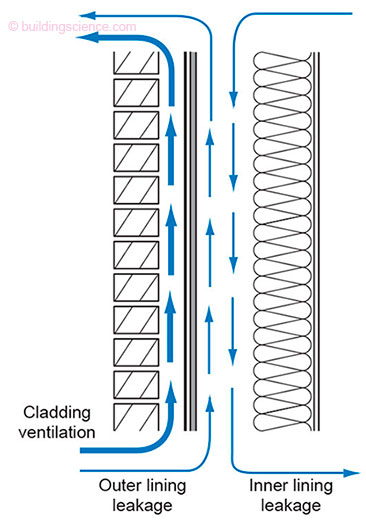
Figure 12: Approximation of Flows (for purposes of modeling)—A “source” and “sink” method to approximate the effect of cladding ventilation and convective (air transported) moisture transport.
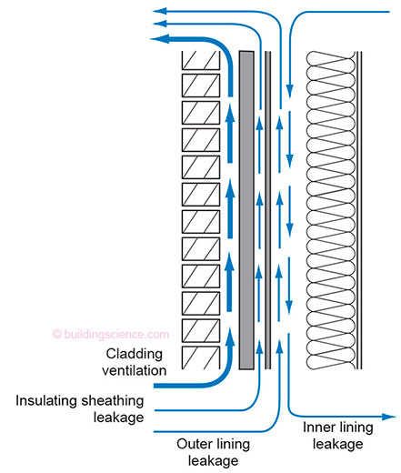
Figure 13: Multiple Layers—Air space coupling to address through the assembly airflow in WUFI.
So what should the flow rates, gap sizes and air changes per hour be for these elements? Check out Table 2. The information in Table 2 comes from a combination of published work (ASHRAE 1091-RP, work done at Oak Ridge, work done at the University of Waterloo) and unpublished work10.
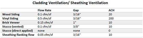
Table 2: Cladding Ventilation/Sheathing Ventilation—Flow rates, gap sizes and air changes per hour be for listed elements are given. The information in Table 2 comes from a combination of published work (ASHRAE 1091-RP, work done at Oak Ridge, work done at the University of Waterloo) and unpublished work.
Bibliography
Kumaran, M., Mitalas, G. and Bomberg, M.; Fundamentals of Transport and Storage of Moisture in Building Materials and Components, ASTM Manual Series: MNL 18, Philadelphia, PA, February, 1994
Künzel, H. (2002). WUFI® PC-Program for calculating the coupled heat and moisture transfer in buildings. Fraunhofer Institute for Building Physics. Holzkirchen, Germany.
Straube, J.F., Moisture Control and Enclosure Wall Systems, Ph.D. Thesis, Civil Engineering Department, University of Waterloo, Waterloo, Ontario, Canada, April, 1998.
Straube, J.F., Burnett, E., VanStraaten, R., Schumacher, C. (2004). Review of Literature and Theory – Report #1. ASHRAE 1091 – Development of Design Strategies for Rainscreen and Sheathing Membrane Performance in Wood Frame Walls. University of Waterloo, Building Engineering Group Report for ASHRAE.
Shi, X., Schumacher, C., Burnett, E. (2004). Ventilation Drying Under Simulated Climate Conditions – Report #7. ASHRAE 1091 – Development of Design Strategies for Rainscreen and Sheathing Membrane Performance in Wood Frame Walls. The Pennsylvania Housing Research/Resource Center, Pennsylvania State University Report for ASHRAE.
Ueno, K. and Lstiburek, J. (2014). Guidance on Modeling Enclosure Design in Above Grade Walls: Expert Meeting Report, NREL, DOE.
Footnotes
- For Canadians and Europeans and others who read this the phrase is an American slang expression that means something will not fulfill its intended purpose. I first heard it in Texas but folks from Arkansas and Kentucky claim it as theirs. The Canadian version is “hosed up” as in “WUFI is all hosed up” and it comes from Rick Moranis who grew up almost next door to me. We are both from Downsview, a suburb of Toronto. Rick is best known as Bob McKenzie—one of the McKenzie Brothers from Great White North. In case you want to know how my mind works check out my favorite clip – “the mouse in a beer bottle”. Rick is credited with coining the phrase “hoser” but we all called ourselves “hosers” in my high school before Rick made it with Second City Television.
- Harry Callahan played by Clint Eastwood from the 1973 movie Magnum Force gives one of the movies best lines: “A man’s got to know his limitations.”
- I own a hammer and a saw – to say that I am a carpenter is a stretch. I built a deck once. I framed houses for a day – before I got fired.
- Similarly we are still waiting for them to figure out the friction thing. Physicists still to this day cannot derive frictional forces from the fundamental forces of nature. Can’t do it with Newtonian Mechanics, Einsteinian Mechanics, Quantum Electrodynamics, or String Theory. We engineers don’t care. We use fudge factors. We don’t call them that because that would upset civilians. We call them “coefficients”. We use the “coefficient of friction” because we don’t have time to wait for the physicists to catch up to us. So in the meantime we engineers live in the coefficient world coupled with judgment and safety factors. And because of this you all have the good life. Cars, planes, trains, electric motors. You are welcome.
- Kumar Kumaran and Gint Mitalas and Mark Bomberg – the “Dream Team” who shared stuff with a young German and his colleagues– young at the time – Hartwig Kunzel.
- John Straube did his doctoral dissertation on the rain wetting of facades and WUFI incorporates his work in providing a reasonable estimate of how much water falls on a wall. Also, as background, ASHRAE 160 uses the Straube rain model. Well done John.
- Big hat tip to the ASHRAE 160 Committee for this. Don’t know who it came from specifically, but thanks to all of you. It has proven to be a very reasonable number. Let me know where this number came from? There has to be a story behind it. There always is a story. ASHRAE 160 says apply the penetrating water to the face of the water resistive barrier (WRB). I and others (see Schumacher) think this is wrong because if we have a reservoir cladding and it is applied to the face of the WRB it does not get into the reservoir.
- ASHRAE 160 also should go the route of assuming 1 percent of the 1 percent penetrates the water control layer and enters into the sheathing.
- Yes, finally the goal for our team has fallen!
- Another big hat tip to Chris Schumacher, Building Science Labs, Waterloo, Ontario.