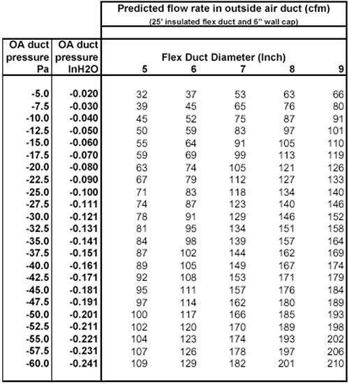
Air flow measurements were taken for 7.6 m lengths of 12.7 cm through 22.9 cm diameter flexible ducts, with a 15.2 cm wall-cap, at duct pressures of -10 Pa to -120 Pa. Using these measurements and field experience, a five-step method was developed as a guide for sizing and installing the ventilation system. An economic evaluation was made by conducting hourly computer simulations to determine the impact on heating, cooling, and fan energy use for four U.S. climates. An effective ventilation system can be achieved using a filtered duct from out doors to the return side of a central air distribution fan with a specialized fan control that automatically cycles the fan if the fan has been inactive for a period of time.
Introduction
Energy efficient homes with low air leakage rates require mechanical ventilation for acceptable indoor air quality [1]. A number of residential mechanical ventilation system types exist. These systems can be generally categorized as follows:
- Supply ventilation, with either central-, single- or multi-point distribution
- Exhaust ventilation, with either single- or multi-point exhaust, and with or without passive inlet vents
- Balanced ventilation, with either single- or multi-point supply and exhaust, and with or without heat recovery or energy recovery (heat and moisture)
Recent related publications describing ventilation systems include [2], [3], [4], [5], [6]. Some economic analysis has been published, however, hourly computer simulations, with real buildings designed to meet national energy standards, and with properly sized heating and cooling equipment has not been published.
Supply Ventilation
Supply ventilation systems draw outside air from a known location and deliver it to the interior living space. This known location should be selected to maximize the ventilation air quality. The air can be treated before distribution to the living space (heated, cooled, dehumidified, filtered, cleaned). If supply ventilation air is not pre-treated, it should be mixed with recirculated indoor air to mitigate discomfort effects of the outside air (at least 2 parts inside air with 1 part outside air). Supply ventilation will tend to pressurize an interior space relative to the outdoors, causing inside air to be forced out through leak sites (cracks, holes, etc.) located randomly around the building enclosure. This strategy is advantageous in warm, humid climates to minimize moisture entry into the building structure from outdoors. Care should be taken with building enclosure design and workmanship when using supply ventilation in climates with cold winters. In some cold climate houses, an exhaust fan may be advisable to balance supply ventilation air to avoid pressurizing the building.
Central-Fan-Integrated Supply Ventilaton System
Ventilation systems that provide ventilation air through a duct that extends from outdoors to the return side of a central air distribution fan have an advantage in that they achieve full distribution of ventilation air using already existing ducts [2]. However, these systems only supply ventilation air when the central fan is operating. During mild outdoor conditions, the fan may not be activated by the thermostat for long periods of time, creating a problem for adequate distribution of ventilation air. Until the introduction of a specialized fan recycling control, the only options to remedy that problem were, 1) run the central fan continuously; or, 2) operate the fan in parallel with a separate timer that had no relation to the fan's operation due to thermostat demand, causing redundant and short-cycling operation. Both of these options are inefficient, and will shorten the life of the central fan. In addition, operating the central system fan continuously can lead to moisture related problems in humid cooling climates. A control [7], [8] can be set to periodically distribute ventilation air during periods when there is no thermostat demand to circulate air for purposes of heating or cooling. The specialized control periodically cycles the fan only if the fan has been inactive for a period of time. This is an energy efficiency strategy that utilizes the normal thermostat driven cycling of the fan for simultaneous distribution of ventilation air. The control can also operate a motorized outside air damper with operation of the central fan but limited to the time set for damper operation on the controller. This serves to disconnect outside air from the house when the fan is not operating, and to limit ventilation air flow if the fan is operating for long continuous periods. This type of central-fan-integrated supply ventilation system can also provide enhanced temperature and humidity comfort control, and air cleaning, through periodic whole house mixing.
As a prerequisite for energy efficiency in any forced air system, the entire air distribution system must be substantially airtight, including all ducts, dampers, fittings, and the air handler cabinet itself. If the air distribution system is leaky to unconditioned space, this will defeat the purpose of intentionally sizing an outside air duct to provide a controlled amount of ventilation air. A good alternative is to locate the entire air distribution system inside the conditioned space.
Ventilation Requirements
Two code jurisdictions in the United States require whole house mechanical ventilation for homes. One is the HUD Manufactured Home Construction and Safety Standards [9], and the other, the Washington State Ventilation and Indoor Air Quality Code [10]. A new code requirement for residential ventilation will go into effect July 1999 in the State of Minnesota.
Test for Determining Outside Air Flow Rates
Measurements were made to establish ventilation air flow rates for central-fan-integrated supply ventilation systems having an outside air duct connected to the return side of a central air distribution fan. Outside air duct configurations included: 15.2 cm wall caps (outside air inlets), 12.7 cm to 22.9 cm diameter flexible duct sizes, and round to rectangular duct transitions with filter. Outside air duct pressures ranged from -10 to -120 Pa.
Test Apparatus Description
All outside air ducts with the associated wall cap, balancing damper, transition, and filter were constructed using off-the-shelf components from local suppliers of HVAC or building products. All flexible ducts were uncut 7.6 m lengths.
All joints between ducts and fittings were sealed with tape (for permanent field installations, fiberglass mesh and mastic should be used). A calibrated fan was used to create the range of negative pressures and to measure air flow. Digital pressure manometers were used to measure the outside air duct pressure upstream of the balancing damper, and to measure fan pressure to calculate the air flow rate from the fan calibration formulas. . .
Download complete report here.
References:
- ASHRAE, 1989. ANSI/ASHRAE Standard 62-1989, Ventilation for acceptable indoor air quality. Atlanta: American Society of Heating, Refrigerating and Air Conditioning Engineers, Inc.
- Reardon, J., C. Shaw, 1997. Evaluation of five simple ventilation strategies suitable for houses without forced-air heating. ASHRAE Transactions, Vol. 103, Part 1, pp. 731-744. Atlanta: American Society of Heating, Refrigerating and Air Conditioning Engineers, Inc.
- Lubliner, M., D. Stevens, B. Davis, 1997. Mechanical ventilation in HUD-Code manufactured housing in the Pacific Northwest. ASHRAE Transactions, Vol. 103, Part 1, pp. 731-744. Atlanta: American Society of Heating, Refrigerating and Air Conditioning Engineers, Inc.
- Sherman, M., N. Matson, 1997. Residential ventilation and energy characteristics. ASHRAE Transactions, Vol. 103, Part 1, pp. 731-744. Atlanta: American Society of Heating, Refrigerating and Air Conditioning Engineers, Inc.
- Holton, J., M. Kokayko, T. Beggs, 1997. Comparative ventilation system evaluations. ASHRAE Transactions, Vol. 103, Part 1, pp. 731-744. Atlanta: American Society of Heating, Refrigerating and Air Conditioning Engineers, Inc.
- Miller, J., C. Conner, 1997. Estimated costs of ventilation systems complying with the HUD Ventilation standard for manufactured homes. Battelle Pacific Northwest Laboratory, PNL-8947/UC-350, November.
- Energy Design Update, 1997. "Controller Improves the Efficiency of Furnace-Based Ventilation Systems." Cutter Information Corp., Arlington, MA. September.
- Builder, 1998. "Space Shot Building Products," Builder Magazine, January. Hanley-Wood, Inc., Washington, D.C.
- HUD 1994. Part 3280 Manufactured home construction and safety standards, interpretive bulletins to the standard, excerpted from the Code of Federal Regulations Housing and Urban Development.
- WSBCC 1997. Washington State Ventilation And Indoor Air Quality Code (1997 Edition), Chapter 51-13 WAC. Department of Community Development, Washington State Building Code Council, Olympia, Washington.