Attics or roofs can be designed and constructed to be either vented or unvented in any hygro-thermal zone (Map 1). The choice of venting or not venting is a design and construction choice not a requirement determined by the physics or by the building code. The model building codes allow both vented and unvented roof assemblies. The applicable physics impacts the design of attic or roof systems as does the applicable building code but neither limit the choice.
Throughout the balance of this digest the terms attic and roof will and can be used interchangeably.
In cold climates, the primary purpose of attic or roof ventilation is to maintain a cold roof temperature to control ice dams created by melting snow, and to vent moisture that moves from the conditioned space to the attic (ventilation acts to bypass the vapour barrier created by most roof membranes). Melted snow, in this case, is caused by heat loss from the conditioned space. The heat loss is typically a combination of air leakage and conductive losses. The air leakage is due to exfiltration from the conditioned space (often because a ceiling air barrier is not present) and from leaky supply ductwork (often because ductwork located in attics is not well sealed) and from penetrations like non-airtight recessed lights. The conductive losses are usually from supply ductwork and equipment located in attic spaces above ceiling insulation (ductwork is typically insulated only to R-6—whereas ceiling insulation levels are above R-30). Conductive losses also occur directly through insulation, or where insulation is missing or thin.
In hot climates, the primary purpose of attic or roof ventilation is to expel solar heated hot air from the attic to lessen the building cooling load. The amount of cooling provided by a well ventilated roof exposed to the sun is very small. Field monitoring of numerous attics has confirmed that the temperature of the roof sheathing of a unvented roof will rise by a few to no more than 10 F more than a well ventilated attic.
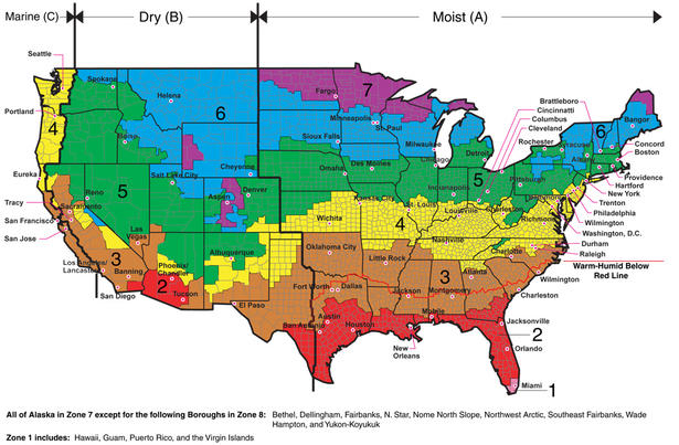
Map 1: IECC/IRC Climate Zones
The amount of attic cavity ventilation is specified by numerous ratios of free vent area to insulated ceiling area ranging from 1:150 to 1:600 depending on which building code is consulted, the 1:300 ratio being the most common.
Control of ice dams, moisture accumulation and heat gain can also be successfully addressed by unvented attic or roof design.
Why Two Approaches – Vented and Unvented?
Vented attic and roof construction has a long history of successful performance. Why change a good thing?
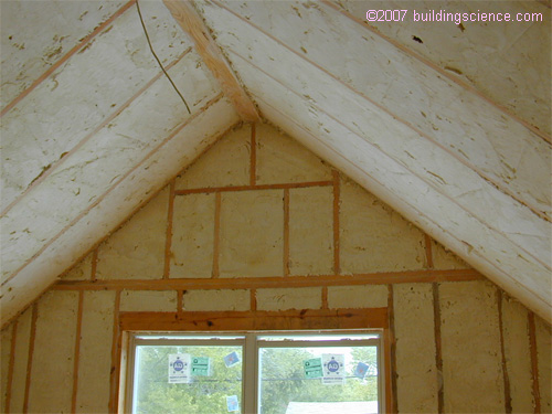
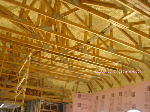
As the complexity of attic and roof assemblies increases, the difficulty to construct vented assemblies also increases. The more complex a roof geometry, the easier it is to construct the assembly in an unvented manner. With complex roof designs, multiple dormers, valleys, hips, skylights combined with cathedral construction with interior soffits, trey ceilings and multiple service penetrations (Photograph 1) it is often not practical to construct a vented roof assembly with an airtight interior air barrier at the ceiling plane.
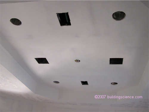
Photograph 1: Ceiling Penetrations – “Swiss Cheese Services”
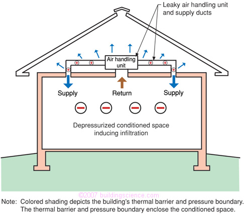
Additionally, it is becoming more common to locate mechanical systems and ductwork in attic spaces in all climate zones. When such ductwork is leaky significant problems can occur (Figure 1). There are significant energy advantages and durability advantages to move the thermal boundary and pressure boundary (air barrier) to the underside of the roof deck (Rudd, Lstiburek, & Moyer; 1997) thereby locating these mechanical systems and ductwork within the building conditioned spaces (Figure 2).

Supply ductwork and air handler leakage can be more than 20 percent of the flow through the system.
Leakage out of the supply system into the vented attic results in an equal quantity of infiltration through the enclosure. In cold climates the heat loss can lead to ice dam creation, in hot humid climates the infiltration leads to high latent loads due to infiltration into the conditioned space. In all climates this leads to thermal penalties – increased energy consumption in the order of 20 percent of the total space conditioning load (Rudd and Lstiburek, 1997).
In hot humid climates condensation on ductwork and air handlers located in vented attics is common.
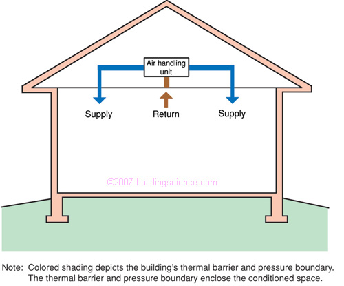
Figure 2: Ductwork Interior to Thermal and Pressure Boundary
Duct leakage does not result in infiltration or exfiltration (air change) as ductwork is located within the conditioned space.
This results in significant energy savings compared to Figure 1.
In high wind regions – particularly in coastal areas, wind driven rain is a problem with vented roof assemblies. Additionally, during high wind events, vented soffit collapse leads to building pressurization and window blowout and roof loss due to increased uplift. Unvented roofs – principally due to the robustness of their soffit construction - outperform vented roofs during hurricanes – they are safer.
In coastal areas salt spray and corrosion are a major concern with steel frames, metal roof trusses and truss plate connectors in vented attics.
Finally, in wildfire zones, unvented roofs and attics have significant benefits in terms of fire safety over vented roof assemblies.
Approach
The main strategy that should be utilized when designing roof or attics to be free from moisture problems and ice dams along with control of heat gain or heat loss regardless of ventilation approach is the elimination of air movement, particularly exfiltrating air in cold climates and infiltrating air in hot and hot humid climates. This can be accomplished by the installation of an air barrier system or by the control of the air pressure difference across the assembly (depressurizing a building enclosure reduces the exfiltration of interior air – pressurizing a roof assembly with exterior air also reduces the exfiltration of interior air).
Air barrier systems are typically the most common approach, with air pressure control approaches limited to remedial work on existing structures (Lstiburek & Carmody, 1994).
Vapor diffusion should be considered a secondary moisture transport mechanism when designing and building attics. Specific vapor retarders are often unnecessary if air movement is controlled or if control of condensing surface temperatures is provided.
Vented Design
Vented attics should not communicate with the conditioned space – they should be coupled to the exterior. Therefore, an air barrier at the ceiling line – such as sealed gypsum board - should be present to isolate the attic space from the conditioned space. Ideally, no services such as HVAC distribution ducts, air handlers, plumbing or fire sprinkler systems should be located external to the air barrier (Figure 3).
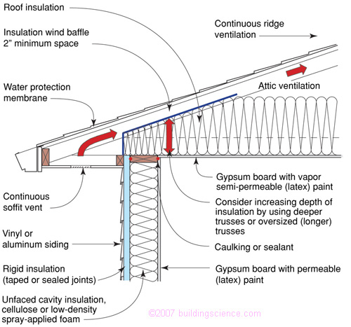
Roof insulation thermal resistance at roof perimeter should be equal or greater to thermal resistance of exterior wall.
1:300 ventilation ratio recommended.
The recommended ventilation ratio to provide for vented attic assemblies when an air barrier is present, is the 1:300 ratio (as specified by most building codes). This is based principally on good historical experience and simple psychrometric analysis (Handegord & Giroux, 1984).
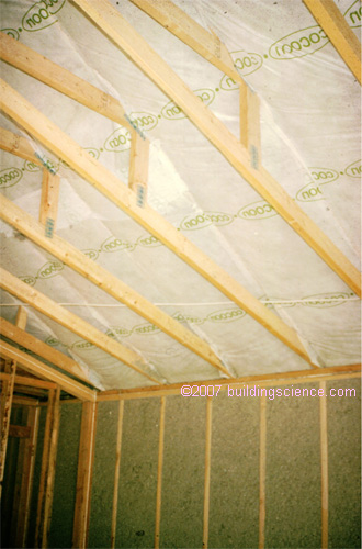
In vented cathedral ceiling assemblies a minimum 2-inch clear airspace is recommended between the underside of the roof deck and the top of the cavity insulation. This is not a code requirement but ought to be (only 1-inch is typically specified in the model codes). It is the author’s experience that typical installation practices and construction tolerances do not result in an airspace of at least 1 inch and rarely is it “clear.” Even when 2” clear space is provided, the rate of ventilation flow will be significantly less than in an open ventilated attic.
In addition to an air barrier at the ceiling line, a Class II vapor retarder (see sidebar) should be installed in Climate Zones 6 or higher (see Map 1).
Class I vapor retarders (i.e. vapor barriers – see sidebar) can be installed in vented attic assemblies in Climate Zones 6 or higher (see Map 1) but should be avoided in other climate zones as top side condensation can occur in summer months during air conditioning periods.
No interior attic assembly side vapor control is required or recommended in climate zones other than Climate Zones 6 or higher (see Map 1) for vented attic assemblies (note the distinction, this is not the case for unvented attic assemblies as will be discussed later). With vented attic assemblies moisture that diffuses into the attic space from the conditioned space is vented to the exterior by attic ventilation.
Unvented Design
Unvented attic design falls into two categories: systems where condensing surface temperatures are not controlled (Figure 4) and systems where condensing surface temperatures are controlled (Figure 5). The two categories essentially are the demarcation between regions where cold weather conditions occur with sufficient frequency and intensity that sufficient moisture accumulation from interior sources can occur on an uninsulated roof deck to risk mold, corrosion and decay problems.
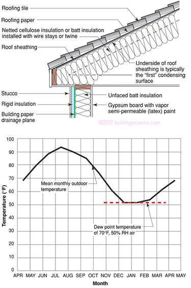
Potential For Condensation in Phoenix, AZ With Unvented Roof (see also curve).
No potential for condensation on the underside of the roof sheathing until interior moisture levels exceed 50 percent RH at 70 degrees F.
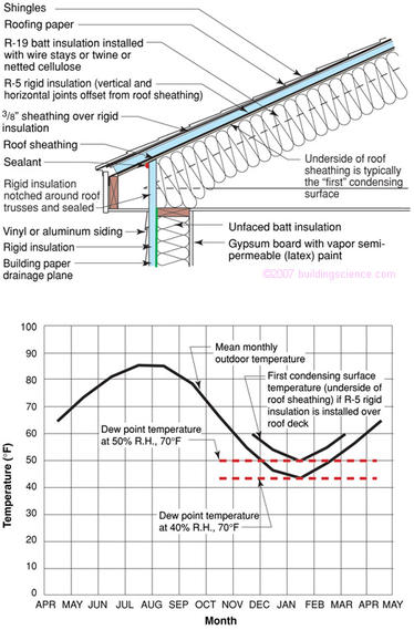
Potential For Condensation in Dallas, TX With Unvented Roof And Insulating Sheathing (see also curve).
Rigid insulation installed above roof deck.
No potential for condensation on the underside of the roof sheathing until moisture levels exceed 40 percent RH at 70 degrees F. when rigid insulation is not present.
Rigid insulation is recommended in this roof assembly to raise the condensation potential above 50 percent RH at 70 degrees F.
Ratio of R-value between rigid insulation and batt insulation is climate-dependent.
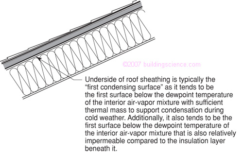
The key is to keep the roof deck – the principle condensing surface in roof assemblies (Figure 6) – sufficiently warm throughout the year or to prevent interior moisture laden air from accessing the roof deck. This can be accomplished in several ways: the local climate may be such that the roof deck stays warm, or rigid insulation can installed above the roof deck, or air-impermeable insulation (typically spray foam – Photograph 2) is installed under the roof deck in direct contact with it.
Where rigid insulation is installed above the roof deck, or air impermeable insulation (spray foam) is installed under the roof deck condensing surface temperatures are said to be controlled.
The climate demarcation is a distinction between regions where the monthly average temperature remains above 45 degrees F. throughout the year and where it drops below 45 degrees F. during the year. An additional criteria is also necessary – that of keeping the interior relative humidity below 45 percent during the coldest part of the year.
These criteria were selected for two reasons. First, by keeping the roof deck above 45 degrees F., condensation will not occur unless the dewpoint temperature of the interior air exceeds 45 degrees F. and this air contacts the roof deck. This interior dewpoint temperature is approximately equal to an interior conditioned space temperature of 70 degrees F. at an interior relative humidity of 45 percent. Higher interior moisture conditions can easily be avoided with air change/ventilation or the avoidance of over humidification during the coldest month of the year in the climate zones specified.
Second, a monthly average temperature was selected, rather than a design heating temperature, as it is more representative of building enclosure performance. Short term, intermittent “spikes” in parameters/environmental loads are of significant interest to structural engineers and in the sizing of space-conditioning equipment, but are not typically relevant to moisture induced deterioration. Wood-based roof sheathing typical to residential construction has sufficient hygric buffer capacity to absorb, redistribute and re-release significant quantities of condensed moisture should intermittent condensation occur during cold nights when sheathing temperatures occasionally dip below 45 degrees F. The average monthly temperatures more accurately reflect moisture content in wood-based assemblies.
The temperature criteria was also based on tile roofing systems not membranes and asphalt shingles. Membrane, metal, and shingle roofs can experience night sky cooling that can depress roof deck temperatures significantly below ambient air temperatures, especially in arid and high-altitude locations. When membrane, metal or shingles are used it is typically necessary install rigid insulation above the roof deck or install air impermeable insulation below the roof deck.
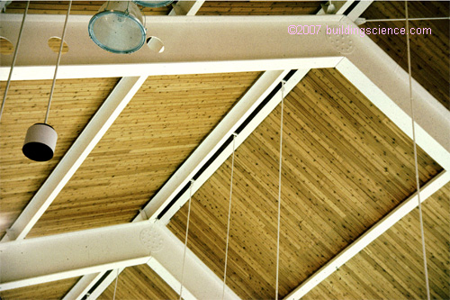
The demarcation between regions that require the control of condensing surface temperatures and regions that do not can be obtained by consulting climate information or from Map 1. Note that both hot-humid and hot-dry climate zones meet the 45 degree F. roof deck criteria. However, the high interior relative humidities found in buildings located in hot-humid climate zones during the winter months do not always meet the 45 percent interior relative humidity criteria. Therefore, the only zone that meets both of these requirements is the hot-dry hygro-thermal region. Only hot-dry climates do not require the control of condensing surface temperatures or the use of air impermeable insulation at the underside of the roof deck (Photograph 3). All other regions require some form of control.
Control of condensing surface temperatures typically involves the installation of insulating sheathing above the roof deck. In residential wood frame construction this involves installing rigid insulation between the roof shingles and the roof plywood or OSB. The installation of the rigid insulation elevates the temperature of the roof deck during cold weather and hence minimizes condensation.
Figure 4 and Figure 5 illustrate the difference between two fundamental systems. Figure 4 shows the potential for condensation of an unvented roof assembly in Phoenix, AZ. Phoenix, AZ is located in a hot-dry climate zone. This roof assembly has no insulating sheathing installed above the roof deck.
Figure 5 shows the potential for condensation of an unvented roof assembly in Dallas, TX. Dallas, TX is located in a mixed-humid climate zone. Note that this roof assembly has rigid insulation installed above the roof deck in order to control the condensation potential. The thermal resistance of the rigid insulation (thickness) necessary to control condensation depends on the severity of the climate. The colder the climate, the greater the resistance of the rigid insulation required.
Figure 7 shows a roof design that is not dependant on controlling interior moisture levels – as the other roof designs previously discussed have been. The absence of cavity insulation in this design yields the highest condensing surface temperature of all of the designs presented. Note that all of the insulation is installed over the top of the roof deck. In this particular design, the condensing surface is the air barrier membrane installed over the wood decking (Photograph 4). The design and configuration of the roof in Figure 7 is consistent with and based on typically constructed flat compact roofs common in commercial construction – it is just that the roof assembly is “tilted” or constructed with a slope (Figure 8). This is the type of roof design most appropriate for swimming pools or other humidified building types in cold climates. It is also one that provides the most durability to the primary components of the structure by keeping these warm and dry.
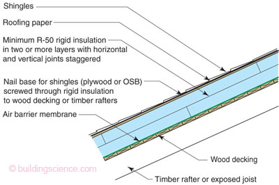
- All insulation located above air barrier membrane.
- Optimum roof design for pool and spa enclosures.
- All insulation located above roof deck.
- Structure exposed to interior inside air barrier and thermal barrier.
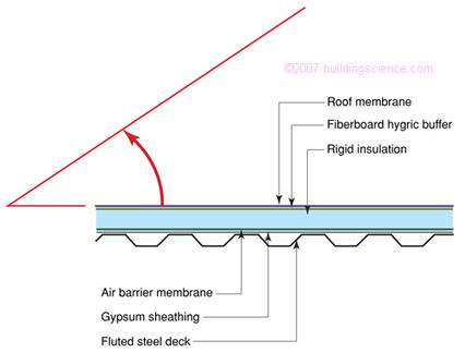
- Historically successful performance not affected if constructed with a slope
In extreme snow regions it is necessary to add a vented air space between the roof cladding (shingles) and the rigid insulation to avoid ice damming (see the digest on ice dams for more information). The vented air space is needed to flush heat away trapped by the insulating value of relatively thick snow (the snow becomes an insulating “blanket”). This approach creates a vented-unvented hybrid roof assembly (Figure 9).
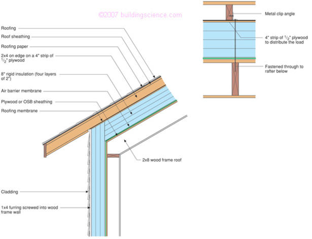
In extreme climates such as high snow load mountain regions a vented space should be provided between the roof cladding and the thermal layer to vent heat.
Note that in these types of unvented roof assemblies (except Figure 7, Figure 8 and Figure 9), interior vapor barriers (Class I vapor retarders – see sidebar) are not recommended as these assemblies are expected to be able to “dry” towards the interior.
Instead of installing rigid insulation above the roof deck to control condensing surface temperature, air-impermeable insulation can be installed in direct contact with the underside of the structural roof deck (Figure 10). Air-impermeable insulations are typically low density or high-density spray foams (Photograph 5). Netted or blown cellulose, fiberglass or rockwool insulation are not considered air impermeable.
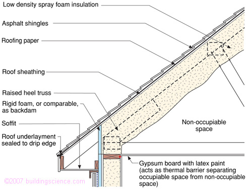
In Climate Zones 5 or higher a Class II vapor retarder is required on the interior of the spray foam layer.
If a high density foam is used in this assembly, a Class II vapor retarder is not required in Climate Zones 5 or higher as the high density foam itself qualifies as a Class II vapor retarder.
A thermal barrier is required to separate spray foams from occupiable spaces due to the fire performance of spray foam insulations.
In Climate Zones 5 or higher (see Map 1) the air-impermeable insulation, including any covering adhered continuously to the bottom side should have a vapor permeance of 1 perm or less (i.e. have the characteristics of a Class II vapor retarder or lower – see sidebar). This can be achieved by applying a vapor retarder paint over the interior surface of the low density spray foam or by installing a material layer in contact with the foam that has a vapor permeance of 1 perm or less.
High density spray foam insulation due to its impermeability properties can be installed directly under roof decks in any climate zone without any additional provision for vapor diffusion resistance - including Climate Zones 5 or higher (see Map 1).
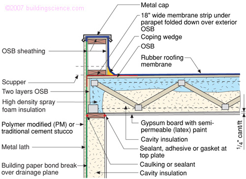
High density spray foam insulation – which is considered an “air impermeable insulation (air permeance of not more than 0.02 L/s-m2 at 75 Pa pressure differential tested according to ASTM E 2178 or E 283 – identical to the definition of an air barrier material in the National Building Code of Canada) can be used in combination with other insulation systems that are not “air impermeable” (Figure 11). In this particular instance the high density foam insulation controls the access of interior moisture to the roof deck by air movement and by diffusion. This approach is similar in effect to the approach described in Figure 12 where rigid insulation is placed above the roof deck.
High density spray foam insulation does not require an interior vapor retarder in any climate
Membrane, metal, and shingle roofs can experience night sky cooling that can depress roof deck temperatures significantly below ambient air temperatures. When membrane roofs and asphalt shingles are used it is typically necessary install rigid insulation above the roof deck or install air impermeable insulation below the roof deck.
The thermal resistance (thickness) of the rigid insulation is climate dependent and moisture load dependent.
The colder the climate the higher the thermal resistance required for the rigid insulation.
The higher the interior moisture load the higher the thermal resistance required for the rigid insulation.
Membrane roofs and shingle roofs can experience night sky cooling that can depress roof deck temperatures significantly below ambient air temperatures. When membrane roofs and asphalt shingles are used it is typically necessary install rigid insulation above the roof deck or install air impermeable insulation below the roof deck.
Effect on Shingle Life
In general, shingles installed on unvented attic assemblies operate at a slightly higher temperature. This has impacts on the durability of roof assemblies. A 2 or 3 degree F. rise in average temperature is typical for asphalt shingles and a corresponding 10 degree F. rise in average temperature for sheathing (Parker & Sherwin, 1998; Rudd & Lstiburek, 1998; TenWode & Rose, 1999).
All other things being equal, applying the Arrhenius equation (Cash et.al, 2005), a 10 percent reduction in useful service life should be expected. This is comparable to the effect of the installation of radiant barriers. What is more significant to note is that the color of shingles and roof orientation have a more profound effect on the durability of shingles than the choice of venting or not venting (Rose, 1991) – double or triple the effect of venting/non venting.
Summary
Both vented and unvented attic/roof designs can be used in all hygro-thermal regions. However, the designs need to be climate sensitive.
Control of ice dams, moisture accumulation and heat gain can be successfully addressed by both vented and unvented attic or roof design.
The choice of the venting approach is up to the designer.
Vented attic/roof designs have the advantage of a long, proven historical track-record. However, they work best with airtight ceiling/attic interfaces and where ductwork and air handlers are not located within attic spaces. The increase in the use of complex roof shapes and cathedral ceilings has resulted in problems with vented roofs.
Unvented attic/roof designs have the advantage of providing conditioned spaces for ductwork and air handlers. However, they require different approaches in different climate locations.
References
Cash, C.G., D.M. Bailey, et al, “Predictive Service Life Tests for Roofing Membranes”, 10DBMC International Conference on Durability of Building Materials and Components, Lyon, France, April 2005.
Handegord, G.O. and G. Giroux, "An Attic Condensation Ventilation Model”, Division of Building Research, National Research Council of Canada, Ottawa, Canada, 1984.
Lstiburek, J.W. and J. Carmody, Moisture Control Handbook, ISBN 0-471-31863-9, John Wiley & Sons, Inc., New York, NY, 1994.
Parker, D.S and J.R. Sherwin, “Comparative Summer Attic Thermal Performance of Six Roof Constructions”, ASHRAE Transactions, June 1998.
Rose, W. B., “More Data on Shingle Overheating with Unvented Roofs”, Energy Design Update, March 1991.
Rudd, A.F. and J.W. Lstiburek, “Vented and Sealed Attics In Hot Climates” ASHRAE Transactions, TO-98-20-3, June 1998.
Rudd, A.F., J.W. Lstiburek, and N.A. Moyer, “Measurement of Attic Temperatures and Cooling Energy Use In Vented and Sealed Attics in Las Vegas, Nevada”, EEBA Conference, Minneapolis, MN, March 1997.
TenWolde, A. and W.B.Rose, “Issues Related to Venting of Attics and Cathedral Ceilings”, ASHRAE Transactions, CH-99-11-4, June 1999.