Unvented cathedralized attic (UCA) assemblies, created by eliminating ventilation and by moving the thermal insulation and air barrier from the ceiling plane to the rafters, immediately below the roof deck, are increasingly common in low-rise residential construction in the hot-humid and hot-dry southern United States. Unvented cathedral ceilings (UCCs) are similar to UCAs with the exception that the interior finish is also installed on the underside of or between the rafters rather than on the underside of the ceiling joists or collar ties. The test program described in this paper sets out to determine whether or not an assembly that meets the new IRC code requirements but is constructed without a vapor barrier and using an air impermeable, vapor permeable, low-density, open-cell sprayed polyurethane foam insulation can perform satisfactorily in the cold wet climates of Seattle, WA and Vancouver, BC (Zone 4C).
Background
The ceilings of North American houses are increasing in both height and complexity. 57% of the respondents in the 2002 Builder Practices Survey (NAHB 2002) reported using ceiling heights of 9ft or higher. Similarly, 66% of the respondents of the 2003-2004 Consumer Preferences Survey (NAHB Economic Group, 2004) expressed a desire for ceiling heights of 9ft or more. These studies suggest a growing demand for larger volume spaces. One way of creating the feeling of larger space without significant increase in volume is through the use of varying ceiling heights (Wilson & Boehland, 2005). As ceiling planes are made higher and more articulated (e.g. through the incorporation of dormers, valleys, hips, etc.) they often require the construction of cathedral ceilings.
This type of ceiling construction is not restricted to the large semi-custom homes of the suburbs. In a June 2005 AIA survey (AIA 2005), 49% of respondents reported an increase in the number of finished basement and attic spaces. Cathedral ceilings are becoming increasingly common in the smaller homes of large urban centers as more homeowners finish attics to make the most use of limited available space.
Cathedral Ceilings
Cathedral ceilings represent the most compact form of roof used in low-rise residential construction. They are formed by applying the finish to the bottom of the rafters, thus minimizing the depth of the roof assembly and maximizing the volume of the living space. The design and performance of cathedral ceilings differ from conventional attics because there is limited depth available for the introduction of insulation or a ventilated airspace.
Ventilated Roof Assemblies
It is common to provide a ventilated airspace in attics or cathedral ceilings in cold climates to control ice dams by minimizing roof temperatures and to remove moisture that is introduced by warm, moist indoor air which leaks into the roof assembly (Figure 1). The practice of ventilating roof assemblies has been adopted by residential builders across North America and has been convention since the 1940s. Experience and research over the past 10 to 20 years have caused many to abandon ventilated roof assemblies in favor of unvented cathedralized attics (UCAs) or unvented cathedral ceilings (UCCs) (Figure 2).
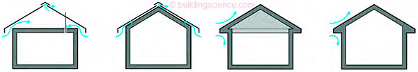
Figure 1 (above left): Ventilated attic (left) and ventilated cathedral ceiling (right) assemblies; Figure 2 (above right): Unvented cathedralized attic (left) and unvented cathedral ceiling (right) assemblies.
Unvented Roof Assemblies
In hot climates, UCA and UCC assemblies prevent the warm, humid air from condensing on cool, inside drywall surfaces or on the cold surfaces of air conditioning ductwork (Lstiburek 2003). Similarly, Rose and TenWolde (1999) suggest that ventilation of roof assemblies in cold, wet climates can result in increased moisture levels and that unvented assemblies may mitigate this problem. In wooded areas, unvented assemblies may provide better protection from wildfire because there are no vents which can permit the entry of burning embers into the roof assembly (Rose and TenWolde 2002, Rudd 2003). In coastal areas, unvented assemblies are less likely to suffer from moisture problems related to wind-driven rain which can enter through vents and wet sensitive materials in the roof assembly (Lstiburek 2006). UCA and UCC assemblies are gaining acceptance and constructed in growing numbers in a range of climates.
Building Code Requirements
In the 2006 edition of the International Residential Code (IRC), Section R806.4, sentence 4 requires that unvented cathedralized attics be designed such that:
In Zones 3 through 8 as defined in Section N1101.2, sufficient insulation is installed to maintain the monthly average temperature of the condensing surface above 45°F (7°C). The condensing surface is defined as either the structural roof deck or the interior surface of an airimpermeable insulation applied in direct contact with the underside/interior of the structural roof deck. “Airimpermeable” is quantitatively defined by ASTM E 283. For calculation purposes, an interior temperature of 68°F (20°C) is assumed. The exterior temperature is assumed to be the monthly average outside temperature.
Under this code provision, it is permissible to construct a UCA assembly using an air impermeable, low-density, open-cell sprayed polyurethane foam installed between framing members directly on the underside of the roof deck. This concept has been used as the basis for an unvented cathedral ceiling assembly proposed for houses in Seattle, WA and Vancouver, BC.
Proposed Unvented Cathedral Ceiling Assembly
The proposed UCC assembly, illustrated in Figure 4, is insulated using a low-density, open-cell polyurethane foam insulation and comprises (from outside to inside):
- Asphalt shingles
- 12.5 mm (1/2 in.) COFI plywood sheathing
- 38 x 89 mm (2 x 4 in.) strapping @ 406mm (16 in.) O.C.
- 38 x 228 mm (2 x 10 in.) rafters @ 406mm (16 in.) O.C.
- 266 mm (10.5 in.) of low-density, open-cell sprayed polyurethane foam
- No polyethylene vapor barrier
- 12.5 mm (1/2 in.) drywall painted
The IRC code requirement does not make any reference to the provision or exclusion of a vapor barrier. Some designers and contractors maintain that it is not necessary while others question this contention, arguing that the relatively high permeance of the interior drywall and the low-density, open-cell polyurethane foam make the roof sheathing in this system prone to excessive moisture content accumulation during the winter season. The need for additional vapor control is the focus of the research project described in this paper.
Previous Research
The hygrothermal performance of roof assemblies has been the focus of only a few North American field measurement studies. Parker and Sherwin (1998) studied the temperatures in 6 conventional ventilated roof assemblies installed in a test hut at Cocoa Beach, Florida, and noted the coolest temperatures in roof systems that had greater thermal mass, lighter colored roof coverings and higher ventilation rates. No moisture content measurements were made.
Winandy et. al. (2000) studied the temperature in 5 ventilated roof assemblies installed in matched south-facing test huts in Madison, WI and Starkville, MS. Black-shingled roofs were found to have peak daytime temperatures 5-10°C higher than lighter-shingled roofs in both climates; during the winter, roof sheathing temperatures were up to 20°C cooler in WI than MS. Moisture content measurements were made periodically using a hand-held electrical resistance MC meter. In non-humidified, ventilated MS attics, the roof sheathing MC ranged from 1.7% in the summer to 7.5% in the winter. In humidified, ventilated MS attics, the range varied from 4% in the summer to 17% in the winter. In non-humidified, ventilated WI attics, the range was from 6% in the summer to 13% in the winter.
Rudd (2005) conducted a field survey of four unvented cathedralized attics in Minnesota and Wisconsin (April 2004) and one such attic in Massachusetts (March 2004.) All five of the unvented cathedralized attics were insulated with low-density, open-cell sprayed polyurethane foam. Foam samples were removed within 1.5m (5 ft.) of the ridge, and the sheathing moisture content was measured with a hand-held electric resistance MC meter. Sheathing moisture contents were highest on north-facing roofs, ranging from 20% to over 40% while measurements on the south-facing roofs ranged from 7-23%.
Rudd found that the sheathing moisture contents were highest in the houses that had abnormally high indoor RH levels as a result of flooding and/or poor ventilation. Rose (2001) reported on one of the only studies to consider cathedral ceiling assemblies. A test hut was constructed in Champaign, Illinois with 3 conventional ventilated attic roof assemblies, 2 unvented cathedralized attic roof assemblies, 1 conventional ventilated cathedral ceiling assembly and 2 unvented cathedral ceiling assemblies. The roof sheathing of unvented cathedralized attic and unvented cathedral ceiling assemblies was 17.7-23.3% hotter than the conventional ventilated attic base case. No moisture content measurements were made.
Research Program
A project was conceived to extend past UCA and UCC moisture monitoring efforts to the coastal climate of the Pacific North West, and more specifically to measure the performance of the proposed unvented cathedral ceiling assembly. A vapor barrier was not used in the proposed UCC assembly. The combination of the painted drywall and the air-impermeable, low-density, open-cell sprayed polyurethane foam is intended to eliminate any convection of water vapor and control the outward diffusion of water vapor during cold weather. The vapor permeance of the interior layers of the assembly is sufficiently high to allow moisture in the sheathing to dry inward during warm weather or in the event of incidental wetting.
A manufacturer of foam insulations arranged for a test house in Vancouver and secured the necessary approvals from the building department. The research program and moisture monitoring system were designed, installed and monitored by the first author’s building science consulting firm. The details of the research program, results and analysis are discussed in the sections that follow.
Objectives
The objective of the field monitoring project was to measure the moisture performance of the proposed UCC and to investigate the need for additional vapor control layers in order to determine if an assembly without these layers could safely accommodate the accumulation of moisture during the winter months and dry quickly enough during the summer months.
Approach
The experimental program was developed to monitor the moisture performance of the UCC using a series of temperature, humidity, moisture content and weather sensors so that the direction of moisture movement, driving forces and amount of moisture stored in the assembly could be determined.
A moisture monitoring system was designed and installed during construction of the UCC test house. The system allows temperature, relative humidity (RH) and moisture content (MC) to be measured at discrete locations on a 5 minute cycle. This method provides excellent temporal resolution but is limited in spatial resolution – sensors only respond to conditions in their immediate vicinity, so they must be located near the action to return useful results.
The indoor RH and temperature are monitored on two floors of the house; however, the indoor conditions are controlled by the occupants rather than the monitoring system. The outdoor RH and temperature are also measured, as are the solar radiation on a horizontal surface and the incidence of wetting (i.e. incidence of rain or dew) on the roof slope. Wind speed and direction as well as quantity of rainfall are not measured.
Industry experience has demonstrated that stick-built assemblies insulated with sprayed polyurethane foam insulation have higher levels of airtightness than conventionally-constructed, batt insulated assemblies. No blower door test or sub-assembly air tightness tests were conducted on the UCC test house. It was assumed that air leakage did not have any effect on the measured performance.
One visit was made to the site during the second fully occupied summer to cut some openings in the assembly, conduct visual inspection of the plywood roof sheathing, make comparative measurements with hand-held meters and to collect samples of the painted drywall for permeance testing. It was not possible to collect samples of the plywood sheathing.
The permeance of the painted drywall samples was determined in the laboratory using ASTM E96 (dry cup method). Wet cup permeance tests were not conducted.
Setup
The moisture monitoring system for the UCC test house is based on the techniques and equipment proposed by Straube et al (2002). Temperature (T) is measured using 10k NTC thermistors (accuracy +/- 0.2°C); relative humidity (RH) is measured using capacitive based sensors with onboard signal conditioning (accuracy +/- 3% between 10 & 90% RH); and moisture content (MC) is measured via in-situ electrical based resistance measurements between corrosion resistant insulated pins. Electrical resistance measurements were converted to %MC by weight, correcting for temperature and species using the Garrahan equation. The data acquisition equipment uses a 13 bit A/D with auto ranging (full scale of +/- 2.5 mV to +/- 2500 mV).
Moisture performance was measured at 4 locations on the north-facing roof slope and 4 locations on the south-facing roof slope as illustrated in Figure 3. Two wall locations were also monitored on each of the north- and south-facing walls, although these are not discussed in this paper.
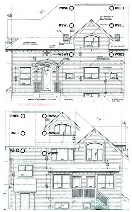
Figure 3: South (top) and north (bottom) elevations showing approximate monitoring locations.
Each monitoring location was given a unique name as an identifier (e.g. RSWU). The four characters of the identifier indicate whether it is a roof or wall location, the elevation, the lateral location and the vertical location. The identifier RSWU, for example, represents the Roof monitoring on the South face, at the West and Upper position. . .
Download complete document here.