Oh the games people play now
ev’ry night and ev’ry day now
Never meaning what they say, yeah
never saying what they mean.
Written, composed and performed by Joe South, released 1968.
Sometimes in order to do the right thing you have to do “a workaround.” I love the “I-Codes.” But they can drive you crazy. I love them because most of the time they are right. In fact almost always they are right. But, every now and then . . . When they are wrong a workaround is called for. I call it “playing the game.”
It is a dirty little secret that the codes display a cold climate bias. It is because the south lost the Civil War. Now it happens that lots of buildings get built in the south. Just for yuks let’s pretend we are going to build a building in Houston, TX. It is pretty obvious that we are dealing with a hot and humid climate. No one has to go to ASHRAE Fundamentals and look at the design conditions. Or even worse go to NOAA.1
Let’s say that we want to construct a wood framed building – say an apartment building with a flat roof that is vented. Very common. Not my first choice for a roof assembly – I am unvented compact roof built up membrane over rigid insulation over a roof deck kind of guy. But, the folks down there sure like their vented flat roofs and they work pretty well and so that is what I typically have to deal with. What does the code have to say about this type of roof? Check it out:
2012 International Building Code
1203.2 Attic spaces…shall have cross ventilation…The net free ventilating area shall not be less than 1/150th of the area of the space ventilated.
Exceptions:
2. The net free cross-ventilation area shall be permitted to be reduced to 1/300 where a Class I or II vapor barrier is installed on the warm-in-winter side of the ceiling.
Yes, you read that right. If you install a vapor barrier you can reduce the vent area. In Houston? A vapor barrier? In a vented attic? It is dumb enough to install a vapor barrier on the inside of a wall in Houston, but in a roof? Now this is clearly wrong. The language was intended to apply only to cold climates. But amazing as it seems the language has been in the code this way from the very beginning. So fix the code, right? Easy to say, tough to do. Not going to happen soon. Well, why not just live with the higher vent area? It gets expensive, that’s why. Do you have any idea how many holes you now need? And big ones at that. Frustrating especially since you don’t need them from the physics perspective. So we play some games.2
What is the intent of the ventilation? To control moisture. It is not to reduce heat gain. The dominant heat transfer mechanism in the roof assembly is radiation and venting the assembly has a negligible effect on the radiation load. Use a light colored membrane with lots and lots of insulation to handle the radiation piece. Increasing vent area to reduce heat gain is not an effective strategy. However, reducing vent area to save costs is a good strategy as long as you don’t reduce it to the point where you now have a moisture problem. What is that lower limit? Ah, a debate for another time. For the sake of brevity and laziness, I am going to stick with the “consensus” value of 1:300. Plus the code allows it.
Ok, we want a roof design with a vent ratio of 1:300. What does the code want? I think Figure 1 pretty much says what the code wants – but with the code you are never quite always sure. Let’s stick with Figure 1. Note where the “vapor barrier” needs to be. This should make you a little nervous with hot humid roof assemblies.
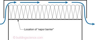
Figure 1: Code Intent—Cross ventilation area and “vapor barrier” location.
The code language gives an option of Class I or Class II. What do these mean? Here is the standard definition:
Class I Vapor Retarder: 0.1 perm or less
Class II Vapor Retarder: 1.0 perm or less and greater than 0.1 perm
Class III Vapor Retarder: 10 perm or less and greater than 1.0 perm
Test Procedure for vapor retarders: ASTM E-96 Test Method A (the desiccant method or dry cup method)
In the south we want to go with the most permeable so we go with the Class II vapor retarder. Note that the code language is not consistent. In the main section it refers to a Class I or Class II vapor barrier, but in the definitions section the word retarder is used. Oh well.
A real roof assembly would probably look like Figure 2. Again, note the location of the Class II vapor retarder. This is troublesome – you really do not want something around 1 perm at that location especially in the summer. But we have a way out. Here comes the work around. Note the test procedure. It is Test Method A. Check out Figure 3. The curve is a thing of beauty. It is a curve that is characteristic of hygroscopic materials.
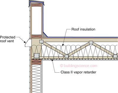
Figure 2: Roof Assembly—Note the location of the Class II vapor retarder. This is troublesome for Houston – you really do not want something around 1 perm at that location especially in the summer.
Figure 3 shows as relative humidity goes up, so does vapor permeance. Where hygroscopic materials are concerned they are only vapor retarders in the absence of vapor. Test Method A (the “dry cup” method) gives you a representative value for the material exposed to an environment around 25 percent RH. When are you ever going to see a RH around 25 percent in Houston? For that roof assembly Test Method B (the “wet cup” method) would be more representative of typical conditions.
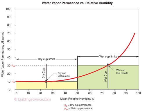
Figure 3: A Thing of Beauty—The curve is characteristic of hygroscopic materials and shows as relative humidity goes up, so does vapor permeance. Where hygroscopic materials are concerned they are only vapor retarders in the absence of vapor. Test Method A (the “dry cup” method) gives you a representative value for the material exposed to an environment around 25 percent RH. When are you ever going to see a RH around 25 percent in Houston? For that roof assembly Test Method B (the “wet cup” method) would be more representative of typical conditions.
What’s with the “cups” terminology? Back in the day we actually used “cups” to test the vapor transmission properties of materials. With the “dry cup” method we kept the “cup” dry with a desiccant. With the “wet cup” method we kept the “cup” wet by filling it with water. Both dry cup testing and wet cup testing establish a 50 percent RH difference across the test specimen. However, with dry cup testing one side is at 0 percent RH and the other side is at 50 percent RH. With wet cup testing one side is at 50 percent RH and the other side is at 100 percent RH (Figure 4). Over time the weight of the cups would change. The dry cup would weigh more over time. The wet cup would weigh less over time. The rate of weight change is tracked and presto we have a metric. The “perm” was born.
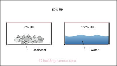
Figure 4: “Cup” Terminology—Vapor transmission properties of materials are tested with both the “dry cup” and “wet cup” method. With the “dry cup” method the “cup” is kept dry with a desiccant. With the “wet cup” method the “cup” is kept wet by filling it with water. Both “cups” are placed in an environmental chamber kept at 50 percent RH. Note that both dry cup testing and wet cup testing establish a 50 percent RH difference across the test specimen. However, with dry cup testing one side is at 0 percent RH and the other side is at 50 percent RH. With wet cup testing one side is at 50 percent RH and the other side is at 100 percent RH (Figure 4). Over time the weight of the cups change. The dry cup weighs more over time. The wet cup weighs less over time. The rate of weight change is tracked and presto we have a metric. Welcome the “perm.”
So what material is available to us that we can use for our work around in our Houston roof? The humble and ubiquitous kraft faced fiberglass batt (Photograph 1). Its dry cup value is 1 perm – so it meets the code requirement of a Class II vapor retarder as tested under ASTM E-96 Test Method A (the desiccant method). Its wet cup value is around 10 perms. So most of the year it is “vapor open” – especially during the most important part of the year for Houston, the hot and humid summer.
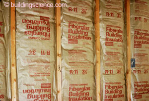
Photograph 1: Kraft-Faced Batt—Humble and ubiquitous with a dry cup value of 1 perm so it meets the code requirement of a Class II vapor retarder as tested under ASTM E-96 Test Method A (the desiccant method). Its wet cup value is around 10 perms.
Are we done with Houston yet? Nope. The batts don’t fit very well in horizontal applications. All kinds of gaps occur between them (Photograph 2). The gaps are not an air lea.k.a.ge issue, but they are a thermal performance issue. What to do? Easy, blow loose insulation over the top of them – use blown fiberglass or blown cellulose. Guess what we call it? Batt and blow. Are we clever or what?
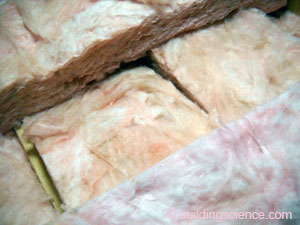
Photograph 2: Mind the Gap— Batts don’t fit very well in horizontal applications. Blow loose insulation over the top of them – use blown fiberglass or blown cellulose. Guess what we call it? Batt and blow. Photograph courtesy of Steven Winter Associates.
What could we do if the code allowed? What type of insulation and vapor control strategy should we use if the code permitted? It seems that the “residential code” has better language. If we were operating under the 2012 International Residential Code rather than the 2012 International Building Code we could just blow loose insulation on top of the ceiling gypsum board until we get to Climate Zone 6. So Climate Zones 1 though 5 “blow is the way to go.” Zone 7 and higher you actually need some type of vapor retarder. Guess what works? The kraft faced batt. You see in the winter the interior RH is low and we get the 1 perm we need.
Now let's get to the next work around. If we are operating under the 2012 International Building Code we probably have to install sprinklers. Ugh. The “ugh” is not because of the sprinklers per say, the “ugh” is because we are now going to run into a fairly complicated and typically stubborn creature – the Fire Inspector. These creatures insist on having all of the insulation installed completely above the sprinklers and the sprinkler lines. Never mind the physics that can easily show that you can bury the lines in loose insulation and not risk freezing if way more insulation is above the lines and heads than below the lines. Don’t confuse the issue with physics. It gets worse, these creatures also insist on seeing the insulation installed completely above the sprinklers before they sign off. The only approach that one can use in this case is once again kraft-faced batt insulation (Photograph 3). You “tent” the sprinkler lines and heads and you are good to go. Don’t forget to blow the loose stuff over the top of the batts. Remember “batt and blow is the way to go.” This holds for all climate zones.
Photograph 3: Tenting—Many “authorities having jurisdiction” insist that sprinklers and the sprinkler lines have insulation only installed above them – no insulation under them – and that they be inspected with the insulation in place before gypsum board is installed. The only practical way to do this is by “tenting” kraft faced batts over them. Don’t forget to blow loose fill insulation over the “tented” batt insulation. Photograph courtesy of Steven Winter Associates.
Are we done yet? Nope. One more thing. A really, really big thing. We need to understand the “bathtub principle.” Check out Figure 5. With vented attics it is real important to have a continuous air control layer (a.k.a. “air barrier”) at the ceiling plane. It is also real important to prevent wind from blowing though the insulation at the roof perimeter (a.k.a. “wind washing”). Think of the roof as a bathtub that is filled with insulation. The sides of the bathtub control wind washing and the bottom of the bathtub controls air lea.k.a.ge from the interior. So where are we going with this? The sprinkler heads can now be a really big problem. They are the holes in the bottom of the bathtub.
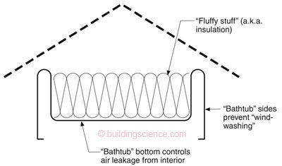
Figure 5: “The Bathtub Principle”—With vented attics it is real important to have a continuous air control layer (aka “air barrier”) at the ceiling plane. It is also real important to prevent wind from blowing though the insulation at the roof perimeter (aka “wind washing”). Think of the roof as a bathtub that is filled with insulation. The sides of the bathtub control wind washing and the bottom of the bathtub controls air leakage from the interior.
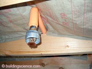
The sprinkler heads and escutcheon plates need to be airtight where they penetrate the ceiling (Photograph 4). Easy, so just seal them. Not so fast. Were they tested “sealed” or “unsealed.” This matters a great deal to that “fairly complicated and typically stubborn creature.” The manufacture of the sprinkler system has to sign off on this. Good luck. Or the “authority having jurisdiction.” Even more luck needed. Or the “architect of record” has to seal the drawing. Sealing the sprinkler heads and escutcheon plates is the “right thing to do” but not often possible because they have not been tested in that configuration and an “exception” has to be granted. An even “better” right thing to do would be for the industry to test their stuff in the “right configuration” – the “sealed” configuration.

Photograph 4: Big Holes— Sprinkler heads and escutcheon plates need to be airtight where they penetrate the ceiling. The problem is have they been tested in this configuration?
What about the “tenting” resulting in an air gap thereby diminishing thermal performance? Forgetaboutit. Too small to worry about if the ceiling is airtight and you go the bathtub route. Doesn’t the thermal barrier have to align with the air barrier? Nope. And that is a discussion for another day.
Footnotes:
Originally a “conglomeration” of the Weather Bureau (formed in 1807) and the United States Coast and Geodetic Survey (formed in 1807) and the Bureau of Commercial Fisheries (formed in 1871). Useful agencies doing useful stuff. Ah, the good old days. Richard Nixon unified the three agencies under the NOAA banner in 1970. He is responsible for the EPA as well. When they were first formed both the EPA and NOAA were welcomed with open arms and sorely needed and did good, timely work. They did clean up the environment – and I for one am grateful.
I am also playing some games in this column – mostly to make a point and to get across a principle dealing with material characteristics. There is another “exception” in this code section that allows the 1:300 ratio to be used without the installation of a “vapor barrier” if the vents are more or less split equally between “high” and “low” vents. I hate this “exception” for vented flat roofs because it means putting holes in your roof…since that’s the only location that meets the “upper” vent location.