If you take rocks and melt them and blow air through them you get fluffy rocks. And fluffy rocks don’t burn. If you take gypsum and make it into sheets you get “sheet rock”. And guess what? Rocks don’t burn.1 Also, metals don’t burn. You can look that up. OK, some metals burn, but you get the idea. If you take wood, which burns, and add rocks and metals to the wood,2 you get wood that does not burn. We could be on to something here.
There are all kinds of places where we have to deal with wildfires and all kinds of places where we build right next to our neighbors. Where we build next to our neighbors we have kind of decided that it is a good idea that if they are on fire that we should not be on fire. And vice versa. This makes things very interesting if we want to vent our roofs or if we want to use continuous insulation on the exterior of our buildings or if we want to do both. And things get even more interesting if we want to vent our claddings.
You want to see a fireman’s head explode mention roof vents, particularly the soffit kind, or air spaces behind siding. It seems that even after 140 odd years the fire folks can’t seem to get over Mrs. O’Leary’s cow.3 Truth be told, good for them. We have the best fire codes bar none in the industrialized world. But every now and then things get irritating code wise if we also want to control other things besides just fire – like water and energy.
With wildfires soffit vents are a problem because burning embers get drawn into the soffit vents and you end up losing the roof. Roof ventilation is prohibited in many wildfire zones for this reason. And it is a good reason. We have the technology to build unvented roofs. The codes allow them. We have covered this before (BSD-102: Understanding Attic Ventilation). So what is the problem?
Well, in places where it snows a lot we need attic ventilation to address ice damming. You can’t just do it with a highly insulated airtight unvented roof. The R-value of the snow cover will raise the snow-roof cladding interface surface temperature above the melt point of the snow even with a “super insulated” unvented roof. We have also covered this before (BSI-046: Dam Ice Dam).
Now it gets interesting. In a wildfire zone where it snows a lot if you don’t vent your roof you will get ice dams. The only technology available to control the inevitable ice dams are snow melt systems. Yech. Is there another option? But of course. Construct a vented roof out of non-combustible materials. Really.
Check out Figure 1. Use rockwool insulation (a.k.a. “fluffy rocks”), fire retardant treated plywood, fire retardant treated wood, metal roofing and fiber cement siding, trim and soffit material (rocks in sheet form) and follow the applicable physics and you get something that handles the embers and the ice dams.
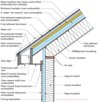
Figure 1: Vented Roof Constructed From Non-Combustible Materials—Use rockwool insulation (a.k.a. “fluffy rocks”), fire retardant treated plywood, fire retardant treated wood, metal roofing and fiber cement siding, trim and soffit material (rocks in sheet form) and follow the applicable physics and you get something that handles the embers and the ice dams. The metal “hat-channel” can be replaced with fire retardant treated wood 2x4’s lying “flat.” The structural geeks like the wood on the flat better. The fire geeks like the metal better. Note that the density of the rockwool will depend on the ground snow load for the location. Works exceptionally well.
The rockwool insulation comes in rigid boards – 4 ft x 4 ft and 4 ft x 8 ft and in 5 lb/ft3 to 10 lb/ft3 densities. This rigid board insulation is installed over the top of two layers of standard rigid insulation such as foil-faced polyisocyanurate or extruded polystyrene. Steel “hat-channels” are installed over the top of this rockwool board insulation. The “hat-channels” are screwed through the three layers of insulation into the roof rafters. The “hat-channels” should be at least 2 inches thick to provide enough airflow to handle ice dams. Fire retardant treated plywood is screwed into the “hat-channels.” A fully adhered membrane4 and metal roof come next.
The fascia, soffit, frieze board and siding are all fiber cement siding. They are all non-combustible. The sub-fascia wood is also fire retardant treated wood. Note that these wood members cannot be “beveled” as they will lose their fire properties. A metal C-section is used as blocking to connect the outer sub-facia to the inner sub-fascia. Note the continuous soffit vent. A beautiful thing.
Could the rigid insulation under the fiber cement siding be rockwool as well? Sure. But it does not have to be. Could the two layers of rigid insulation on the top of the roof sheathing and under the rockwool also be rockwool? Sure. But they do not have to be.
Could the cavity insulation in the in rafter space be cellulose or fiberglass? Sure. Knock yourself out. How about the wall cavity insulation? Same answer.
Could I construct Figure 1 as a conditioned unvented attic assembly rather than a cathedral ceiling? Sure. Just omit the gypsum board.
Ah, but what if I want to use spray polyurethane foam in the rafter space? Check out Figure 2. One layer of rockwool rigid board insulation provides the fire protection on the top side of the structural roof deck. The spray polyurethane foam (SPF) handles the condensation control. Note that in IECC Climate Zones 5 and higher the SPF must be 2 lb/ft3 density. The gypsum board layer need not be installed if the assembly is an attic space rather than a cathedral ceiling. However, in such cases, an intumescent fireproofing coating applied to the interior surface of the SPF will likely be necessary for fire protection on the bottom side of the assembly.
Now lets have some fun. Let’s take Figure 2 and rotate it so that it is vertical and call it a wall. Modify it a bit and we get Figure 3. Paperless exterior gypsum board (a “sheet rock” – recall that rocks don’t burn) is used as an exterior sheathing to support a fully-adhered membrane (or a liquid applied membrane) water control, air control layer and vapor control layer. Over these three control layers goes the rockwool thermal control layer. Recall that “fluffy rocks” don’t burn. A non-combustible fiber cement cladding is attached through the rockwool thermal control layer using a ¾ inch metal “hat-channel” furring/spacer strip. Looks like the “perfect wall” doesn’t it? We were here before as well (BSI-001: The Perfect Wall).
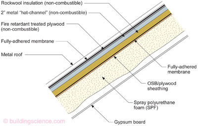
Figure 2: Non-Combustible Vented Roof With SPF—One layer of rockwool rigid board insulation provides the fire protection on the top side of the structural roof deck. The spray polyurethane foam (SPF) handles the condensation control. Note that in IECC Climate Zones 5 and higher the SPF must be 2 lb/ft3 density. Same comment as for Figure 1 - the metal “hat-channel” can be replaced with fire retardant treated wood 2x4’s lying “flat.”
If you really want to make the fire folks a happy bunch fill the cavity with cellulose insulation5 and cover it with Type X gypsum board on the inside. Consider this assembly as the Mrs. O’Leary Cow Assembly. If her barn had been enclosed with this wall we would not have had that little Chicago barbeque in 1871. This assembly is my perfect gift to the City of Chicago. Well it is almost perfect for Chicago. Still working on the bulletproof part to handle the drive-bys.
Do you have to use borate treated cellulose in this wall? No. Fiberglass works just fine. So does SPF. Do you have to use Type X gypsum board? Possibly. Why? Ah, sometimes the code folks want a fire rating for this wall and in the sometimes bizarre world of fire ratings most assemblies are rated for a fire inside a building burning towards the outside where what most of us are looking for is the performance of the wall with a fire on the outside of a building burning towards the inside.6
The water control layer and air control layer and vapor control layer in Figure 3 needs to have some vapor resistance. It should be at minimum a Class III vapor retarder (1.0 to 10 perms) or less to handle the inward vapor drive out of the fiber cement “reservoir cladding.”
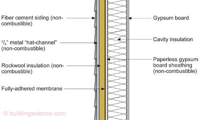
Figure 3: My Gift to Chicago—Paperless exterior gypsum board (a “sheet rock” – recall that rocks don’t burn) is used as an exterior sheathing to support a fully-adhered membrane (or a liquid applied membrane) water control, air control layer and vapor control layer. Over these three control layers goes the rockwool thermal control layer. Recall that “fluffy rocks” don’t burn. A non-combustible fiber cement cladding is attached through the rockwool thermal control layer using a ¾ inch metal “hat-channel” furring/spacer strip. Yes, this metal spacer can be replaced with fire retardant treated wood furring. But check with the fire folks first.
What if I do not want to deal with exterior gypsum board sheathing and a fully adhered membrane or liquid applied layer over the top of the exterior gypsum board sheathing? Check out Figure 4. We will call this the “Detroit Wall”. Lots of fires there lately - going to have a lot of rebuilding to do. In this assembly the water control layer and air control layer function of the fully adhered membrane or liquid applied layer over the exterior gypsum board is replaced with a taped foil-faced polyisocyanurate or extruded polystyrene. The rockwool and cladding attachment stays the same.
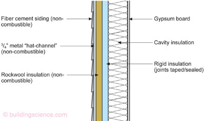
Figure 4: The “Detroit Wall—In this assembly the water control layer and air control layer function of the fully adhered membrane or liquid applied layer over the exterior gypsum board in Figure 3 is replaced with a taped, foil-faced polyisocyanurate or extruded polystyrene. The rockwool and cladding attachment stays the same. Same note about wood furring being used as before.
So why do I want an air gap between the exterior cladding and the continuous rigid insulation? I can see needing it to control ice dams on roofs, but for walls? Ah, we have to deal with rain and hydrostatic pressure. And, yes, we were also here before – BSI-057: Hockey Pucks & Hydrostatic Pressure. It also makes it easy to attach the cladding over the rigid insulation.
This attachment thing can get complicated when we are retrofitting masonry walls on the exterior. But have no fear, there is a solution to this as well. Figure 5 uses wood 2x4’s on the flat tappconned into the masonry to provide a structural transition for the cladding attachment. A liquid applied water and air control layer is applied directly to the masonry prior to the installation of the 2x4’s. Rigid insulation is installed between the 2x4 furring and then a continuous layer of rockwool is installed. The exterior fibercement cladding is installed as before.
In Figure 5 can I use rockwool between the wood structural transition members? Yes. Do these 2x4’s need to be fire retardant treated? No, but check with the “authority having jurisdiction”. Can I install more layers of continuous rigid insulation if I want to go “super-insulated”? Yes. What about the structural implications of all this?
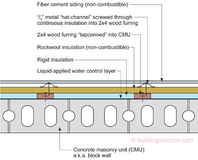
Figure 5: CMU Wall—Wood 2x4’s on the flat are tappconned into the masonry to provide a structural transition for the cladding attachment. A liquid applied water and air control layer is applied directly to the masonry prior to the installation of the 2x4’s. Rigid insulation is installed between the 2x4 furring and then a continuous layer of rockwool is installed. The exterior fibercement cladding is installed as before.
I love structural engineering and structural engineers. Especially the older ones. They build stuff and break it to see what happens. Then once they know the answer, they make sure the calculations work. Check out Photograph 1. How do you figure out how to attach cladding through various types of rigid insulation? You build a whole bunch of assemblies and see. There is no other way. Really. How do you stress the assemblies? Check out Photograph 2. Fill 5 gallon plastic pails with rocks and hang them from the assemblies. And wait. And wait. And still wait. You have to wait a long time. This “creep” thing might creep up on you and you don’t want to be surprised. Surprises are bad if you are an engineer. The simple tests get you enough information to do more detailed tests (Photograph 3) and then you get to write papers and get graphs and stuff (Figure 6). The deflection testing shown here is from a nice piece of work done by Mr. Baker and Mr. Smegal in the Skunk Works at our lab in Waterloo, Ontario.7 The adult supervision for this work came from Professor John Straube of the University of Waterloo. Waterloo has a pretty reasonable engineering school, but not a great as the engineering school at the University of Toronto.
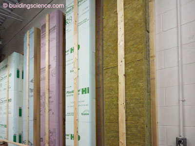
Photograph 1: Build Stuff and Break It—The only way to know is to test it to failure and then you know. How do you figure out how to attach cladding through various types of rigid insulation? You build a whole bunch of assemblies and see. There is no other way.
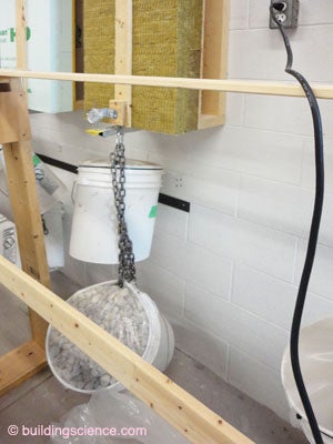
Photograph 2: Stress Test—How do you stress the assemblies? Fill 5-gallon plastic pails with rocks and hang them from the assemblies. And wait. And wait. And still wait. You have to wait a long time. This “creep” thing might creep up on you and you don’t want to be surprised. Surprises are bad if you are an engineer.
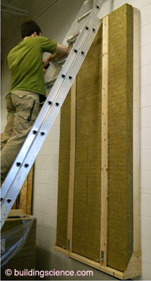
Photograph 3: Detailed Test—The simple tests get you enough information to do more detailed tests The deflection testing shown here is at our Skunk Works.
We can do a lot with fluffy rocks, sheet rocks, metals, fluffy treated paper, metal and salt treated wood and good old-fashioned trial and error. Knowing the physics helps too. But build it and see first, just in case you don’t know all of the physics. Note to self – no one ever knows all of the physics.
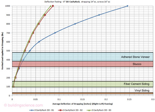
Figure 6: Deflection Testing—A nice piece of work from Mr. Baker and the Skunk Works at our lab in Waterloo, Ontario.
Check out the footnote to get the entire report.
Footnotes:
I heard this the first time as a youngster listening to one of the “Masters” – Rene Dupuis – in a class on roofing in Madison, WI. Rene and Carl Cash were the guys I learned roofing from. Wow, I was one lucky guy. Rene had me laughing and learning for two days. He was charismatic, charming and drank red wine. I wanted to be just like him. Rene, if you ever read this footnote thank you for being such an inspiration. Your son turned out alright as well. Nicely done.
Add boron, sodium, phosphorous which are metals and minerals (a.k.a. “rocks”) and a bunch of other stuff you get fire retardant treated plywood.
Catherine O’Leary’s cow is often blamed for starting the Great Chicago Fire. Turns out that this was a made up story published at the time by the Chicago Tribune. The reporter made it all up “because he thought it would make colorful copy”. Apparently journalism has not changed all that much since then.
Always install a fully adhered membrane under a metal or steel roof. There are only two kinds of metal roofs: those that leak and those that will leak…
Lots of borates in cellulose insulation make for a very happy fire performance. Who would have thought that you could get “fluffy paper” not to burn? I like borate treated cellulose, it is the best use for the NY Times I can think of…. Side note, do not get the ammonia treated cellulose – smells like someone has peed into your wall and is highly corrosive to boot.
These assemblies have not been “officially burned” to get a specific “rating” but we have never had a problem with the “authority having jurisdiction” as it is pretty obvious that fiber cement claddings do not burn and rockwool does not burn and metal hat channels do not burn. We have done this in Chicago and been blessed by the fire guys. If it flies in Chicago…Having said all of that, they are on track to get “officially burned” closing the regulatory loop.
The engineering basis for attachment of claddings through various rigid insulations including rockwool can be found at the following link. A “hat tip” to Peter Baker of our firm for this work and to the U.S. Department of Energy’s Building America Program for supporting it. (BA-1204: External Insulation of Masonry Walls and Wood Framed Walls).