The purpose of this research program was to determine the impact resistance performance of advanced framed wall systems with insulating sheathing as the primary sheathing from wind blown debris. With no standards available for testing wall assemblies, a window industry standard ASTM E1886-05 and E1996-05 Missile Level D, Wind Zone 1 and Wind Zone 2 Enhanced Protection and Wind Zone 3 Basic Protection Standard was used as a starting point for the research. The testing results indicate that high performance wall assemblies provide equivalent or even better impact performance then standard wall assemblies.
Introduction
In recent years significant changes to the residential building industry have been made. The drive for high performance building enclosures fueled by the need to create more energy efficient buildings has opened the door for new building systems, materials, and technology in the market. Understanding the properties of the various materials led to integrated enclosure design that increased the energy efficiency of the enclosure assemblies while optimizing the material use to ensure that the new approaches were still cost effective. These new systems, while they may in many aspects still resembled traditional building assemblies, are in fact significantly different.
Advanced framed wall systems that use that use a stud spacing of 24 inches on center and eliminate the plywood or OSB sheathing from the wall and replace it with insulating sheathing is type of enclosure assembly that has been designed to be energy efficient combined with efficient material use. With the significant changes that have been made to the assembly from traditional designs, old performance standards cannot be assumed. Water and moisture management performance, being integral to the long term durability of enclosure systems have been evaluated and integrated into the design of the system, however other performance standards also need to be addressed. In high wind zone locations such as hurricane and tornado prone zones, additional performance standards are needed such as lateral load resistance (addressed in other research) and impact resistance from wind blown debris.
The purpose of this research program was to determine the impact resistance performance of advanced framed wall systems with insulating sheathing as the primary sheathing from wind blown debris. A research plan was implemented to physically test various advanced framed wall systems for impact resistance.
Impact Protocol
In order to compete the research a standard (baseline) needed to be established to which the panels could be tested. Relevant standards for testing the impact resistance of wall assemblies were researched, however it was found that no standards were available. Since no specific testing protocol existed for wall systems, direction was taken instead from the window industry to create a test protocol.
The test protocol used was based on ASTM E1886-05 and E1996-05 Missile Level D, Wind Zone 1 and Wind Zone 2 Enhanced Protection and Wind Zone 3 Basic Protection Standard. The ASTM Missile Level D Standard requires that an 8ft (+/- 4”), 9lb (+/- 0.25lb), Yellow Pine or Douglas Fir 2x4 be launched with a muzzle velocity of 50.0 fps (+/- 2%) at a minimum of 1 ½ times the length of the 2x4 from the face of the test specimen within 2 ½” radius of the designated impact location.
This test protocol was used as the baseline to test various wall panels to determine their impact resistance. The criterion used was a simple pass/fail metric, where if the 2x4 penetrated all the way through the wall assembly (past the interior face of the framing members) the system did not pass. If the 2x4 did not penetrate all the way through to the inside face of the framing members then the wall system passed.
Test panels
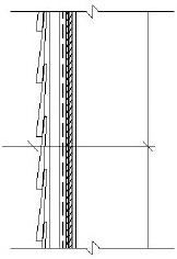
The test panels were designed to emulate the conditions of actual wall assemblies in the field. The panel heights were 8’- 1” with an anchored sill plate and out of plane restrained single top plate to simulate the connection to the roof trusses. The panel widths were 6’- 1 ½” wide and consisted of three 24 inch 2x6 stud bays.
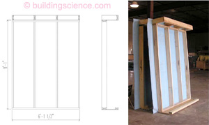
Figure 1: Test panel configuration
Four wall systems were constructed as part of the testing with two wall panels of each design being constructed. The wall systems consisted of one baseline wall panel (representing current standard residential construction practices) and three advanced wall systems (each subsequent wall panel building of the initial panel and designed to be more resistant to impact than the previous panel). To be more conservative, batt or loose cavity fill insulation and interior drywall were not included in the panel design.
The wall systems tested were as follows:
Wall 1
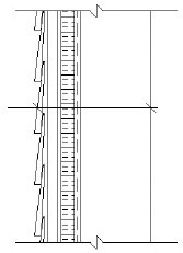
- 2x6 @ 24” OC wall construction
- DOW Weathermate Plus housewrap installed horizontally to the exterior of the suds, with a minimum 6” vertical overlaps, and fastened to the framing with 1-1/2” cap nails spaced 6” OC.
- 1” Styrofoam Residential Sheathing insulating sheathing fastened to framing with 2” cap nails
- Hardie Board fibercement siding installed with 1x4 furring strips.
Wall 2 (Wall 1 + high density closed cell spray foam)
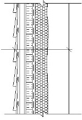
- 2x6 @ 24” OC wall construction
- 2” of high density closed cell spray foam
- DOW Weathermate Plus housewrap installed horizontally to the exterior of the suds, with a minimum 6” vertical overlaps, and fastened to the framing with 1-1/2” cap nails spaced 6” OC.
- 1” Styrofoam Residential Sheathing insulating sheathing fastened to framing with 2” cap nails
- Hardie Board fibercement siding installed with 1x4 furring strips.
Wall 3 (Wall 2 + snow fence material)
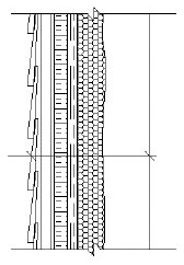
- 2x6 @ 24” OC wall construction
- 2” of high density closed cell spray foam
- DOW Weathermate Plus housewrap installed horizontally to the exterior of the suds, with a minimum 6” vertical overlaps, and fastened to the framing with 1-1/2” cap nails spaced 6” OC.
- GSI Heavy Duty Snow Fence installed with 3” nails at 6” OC.
- 1” Styrofoam Residential Sheathing insulating sheathing fastened to framing with 2” cap nails
- Hardie Board fibercement siding installed with 1x4 furring strips.
Wall 4 (Baseline Wall)
- 2x6 @ 24” OC wall construction
- ½ “ OSB sheathing
- DOW Weathermate Plus housewrap installed horizontally to the exterior of the suds, with a minimum 6” vertical overlaps, and fastened to the framing with 1-1/2” cap nails spaced 6” OC.
- Hardie Board fibercement siding installed with 1x4 furring strips.
The impact location (middle of center stud bay) was also chosen so that material reaction would be consistent with the boundary conditions found in the field (stretch/tear of house wrap at nail heads, stud deflection, etc).
All of the walls tested were clad with fiber cement siding over 1x4 furring strips. This was chosen as a middle ground for performance. As the cladding varies, the impact resistance will vary as well. It can be assumed that cladding systems such as brick veneer and stucco will likely be more resistant to impact than siding materials such as fiber cement and wood. Conversely, vinyl siding will likely provide the least amount of resistance for a wall assembly.
Impact Testing
The initial phase of testing of advanced framed wall system with insulating sheathing as the primary sheathing was completed on June 15, 2006. The testing was done with the help of Cardinal Glass Industries at their Laminated Glass Factory in Amery Wisconsin. Each panel was clamped at the top and the bottom to a metal frame to provide the out of plane resistance for the panels.
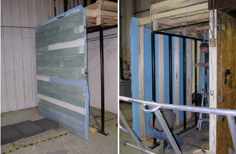
Figure 2: Front and back of wall test set up
An air cannon was used to launch the 2x4 projectile at the test velocity1.
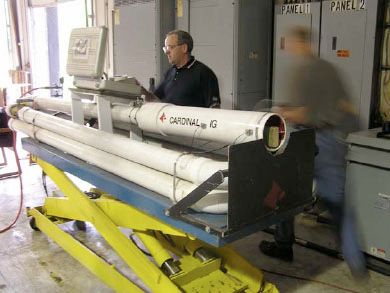
Figure 3: Air cannon
Impact at 50.0 fps
Penetration failures were observed with all of the wall systems (including the OSB sheathed wall) at this stud velocity. These results were surprising as it was expected (based on information from other sources) that the OSB wall would be adequate to resist the impact. . .
Download complete report here.
Footnotes:
- The velocity of the studs cannot be directly controlled. The air cannon is pressurized to a certain air pressure before firing and the velocity of the stud is measured during each test. Due to this, slight variations to the stud velocity are common during the testing. In addition, the alternate velocities were determined by choosing alternate air pressure levels and measuring the corresponding velocities. This is why the velocity for the third tests ended up on an odd number.