Pitched roofs of either wood rafter and joist or truss construction are used in the construction of literally millions of homes and small commercial buildings each year. There are variations in these roofs, but there are relatively few primary options. The following digest describes the most common types of wood pitched roofs, their enclosure functions, and common modes of failure.
Introduction
Roofs must fulfill the same basic functions as all building enclosure elements. These functions can be categorized as: support, control, and finish and sometimes the distribution of services (a building function) is imposed on the enclosure. The distribution of plumbing stacks and forced air conditioning systems within the roof enclosure can have a profound impact on behavior.
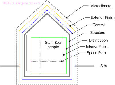
Figure 1: Building and Enclosure Functions
In most practical construction, the enclosure is assembled from numerous layers, and increasingly, these layers have a specific function. For housing, the following break down is useful
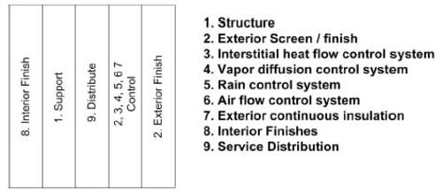
Figure 2: Enclosure Functions and Layers
Typical Roof Assemblies
Consider the typical wood frame attic shown below in Figure 3. This is the most common type of wood roof, with a pitched water-shedding surface, a horizontal ceiling plane which supports insulation, separated by an attic space ventilated with outdoor air. Common materials/systems for functions 1 through 8 are listed on this drawing.
The choices for support function (1) are provided either by a rafter systems (essentially a structural beam with bracing provided by joists, collar ties, parallel walls or a combination) or a truss system (which produces no outward thrusts and is a self-contained element). The exterior screen and finish (2) are typically composition shingles, wood shakes, metal panels, or concrete or clay tiles. The interior finish (8) is almost always one of painted drywall, textured coating on drywall, vinyl wallpaper or wood paneling.
Figure 4 describes the most common assembly geometry that results in a cathedral ceiling. In this case a ventilation space is kept above the insulation to provide a path for ventilation airflow between the ridge and soffit. This system often experiences performance problems in cold weather since the rate of ventilation is often quite small (due to the friction with the sides of the small space, the length of the run, the high probability of misplaced batt insulation blocking flow, and the many areas on roofs that do allow direct connections between the ridge and soffit). If air can leak outward during cold weather (i.e., an air barrier is not provided, or it has been breached by a light fixture, interior partition wall, etc.) the ventilation gap provides an easy means of exiting the roof system. In this scenario, the ventilation of the roof encourage the outward flow of indoor air and encourages significant amount of condensation that cannot easily be subsequently dried.
An alternate, more successful method of building this type of roof is to use scissor trusses, which result in a much larger, less obstructed ventilation gap and provide many opportunities for ventilation cross flow (overcoming the problems with dormers and chimneys).
Unvented cathedral ceilings (Figure 5) were developed to deal with some of these problems. However, these systems require both excellent air flow control — both the avoidance of convective loops and through roof air leakage — and the control of vapor diffusion wetting of the roof deck during cold weather. The drying potential of these systems are lower than most, as they rely exclusively on diffusion to remove moisture that unintentionally enters or is built in. Such can, and have for many years, work well if properly designed for the interior conditions and exterior climate. Proper design requires control of both airflow and vapor diffusion. Although an air barrier system made of drywall or sheet polyethylene can in theory meet the requirements, practice has shown that most builders cannot provide sufficiently airtight ceilings in most buildings. Given this reality, such roofs are usually recommended with air impermeable and vapor retarding spray foam insulation that control both convective loops and through flow of air.
In Zones 1 through 3, open cell (vapor permeable) foam can be used successfully to enclose building spaces with moderate or dry interior humidities. In colder zones (Zone 4 and 5) open cell foam will require additional vapor control on the interior (in the form of spray applied vapor retarding paint). In cold zones (Zone 6 and higher) a closed cell foam is generally required. Dense cellulose can control convective loops, and provides significant amounts of safe storage capacity. However, in Zones 4 and higher, additional vapor diffusion and airleakage control (in the form of vapor retarding paint coatings and sealed drywall respectively) are required. In higher interior humidity spaces, closed cell foam or other roof designs are recommended.
Locating a continuous air impermeable insulation layer on the exterior of the roof in Figure 5 results in an assembly such as Figure 6. The application of the insulation brings the temperature of the sheathing on the rafters closer to the interior temperature. This reduces or eliminates the likelihood and severity of condensation due to outward air leakage and the foam controls inward vapor diffusion from moisture-storing roof materials.
This system can be used in all climate zones provided that the R-value of the air impermeable and vapor semi-permeable insulation placed on the exterior is sufficient to stop air leakage from condensing on the inner surface during cold weather. The standard design approach is to ensure that the monthly average interior dewpoint temperature is less than the interior temperature of the foam insulation layer.
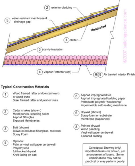
Figure 3: Typical Pitched and Ventilated Attic

Figure 4: Typical Pitched and Ventilated Cathedral Ceiling

Figure 5: Typical Pitched and Unventilated Cathedral Ceiling
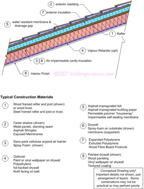
Figure 6: Pitched and Unventilated Cathedral Ceiling with Exterior Insulation
Common Roof Failures
The most common roofing failures relate to rain and snow melt water leakage past the sheathing and into the structure and insulated portions of the assembly. Small leaks (such as occasional drips at nail holes) can be tolerated by storage and drying of the moisture, but larger leaks often result in rapid decay and damage to interior finishes. Hence, the most important goal of design must be to provide an uninterrupted drainage plane with appropriate detailing at roof penetrations (e.g. chimneys, plumbing stacks, skylights) and projections (dormers, 2nd storey roof intersections with low roofs).
In climates with some cold weather, another common failure occurs because interior air, with a dewpoint temperature the same as or higher than the exterior air temperature, leaks into the roof through an imperfect air barrier, passes through cracks and air permeable insulation, and condenses on the underside of the cold roof sheathing (Figure 7). Ventilation with outdoor air can dilute the air in the vent space and thereby reduce the quantity and likelihood of condensation due to this mechanism, but ventilation is normally not sufficient to overcome gross ceiling plane leaks, high interior dewpoint temperatures and/or high driving pressures.
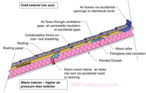
Figure 7: Air Leakage Condensation in Ventilated Cathedral Ceiling
In some cases, air leakage from interior, through the roof assembly, and back into the building, can result in the same type of condensation damage (Figure 8) as through-roof air leakage.
Both types of air leakage condensation damage will be worse when the exterior temperature is low (almost always at night when the sun provides little solar heating to the roof), the interior humidity is high, and the interior air pressure is higher than exterior (caused by a combination of wind forces, thermal buoyancy, and mechanical equipment pressurization).
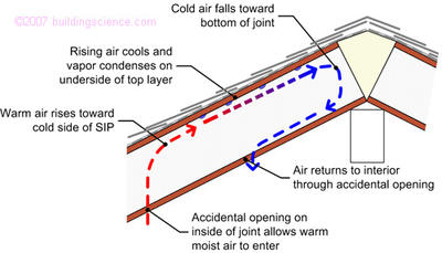
Figure 8: Convective loop condensation processes in roofs (in this case joint in SIPS)
A less common failure mechanism is the result of moisture stored in roof finishes (especially wood shakes, but also in roof tiles) or held in small gaps (between asphalt shingle laps) being driven inward when heated by solar exposure. This vapor drives to the inside and can then condense on the interior finish layers or vapor barrier if present.
Finally, ice dams cause damage by both leakage and mechanical damage to roofs with poor insulation, poor ventilation, or both, in climates that have relatively high snowfalls and moderately cold temperatures. High levels of continuous insulation and/or ventilation below the roof sheathing is required to reduce the likelihood of ice dams. Even so, some dams can still occur, and a waterproof layer in the lower parts of the roof is recommended in susceptible climates. Ice dams are covered in a separate roof document.