The effects of solar heating potential and nocturnal cooling potential are simulated in a controlled indoor environment and extensive measurements are made along and between the boundary surfaces. Air delivered to the test section is controlled to close tolerances in temperature, humidity and flow rate. Steady state conditions, step changes, functional changes or real weather conditions can be simulated. Accurate measurements are taken at the inlet and outlet of the test section to determine the amount of heat and mass transfer across the system. A description of both the DESRAD concept and the Diurnal Test Facility is presented here along with examples of the model verification data and a brief measurement uncertainty analysis.
Introduction
The DESRAD cooling concept is a passive cooling approach which integrates a desiccant bed within a conventional roof structure to achieve both latent and sensible cooling in hot, humid climates. It's original development was by Fairey et al. (1986). Figure 1 illustrates the principle of operation which involves two modes — a nighttime adsorption mode and a daytime desorption mode. The DESRAD concept uniquely takes advantage of nocturnal cooling potential to shed the heat of adsorption during the night, solar heating potential for desiccant regeneration during the day, and the moisture and thermal capacities of household materials to provide energy storage. Results from the analytical model by Swami et al. (1989) have shown significant cooling energy savings and peak electrical load reductions in hot, humid climates. A comparison of the cooling load requirements for a base house and a DESRAD house in Atlanta, GA is shown in Figure 2. The savings for total, sensible, and latent loads are 79%, 81%, and 75%, respectively.
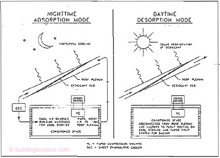
Figure 1: DESRAD operating modes
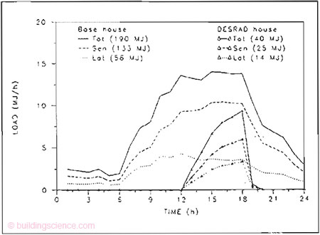
Figure 2: Comparison of summer day cooling load requirements for base and DESRAD houses in Atlanta, Georgia
Experimental Facility Description
The Diurnal Test Facility (DTF) is veing used to provide experimental data needed to verify the accuracy fo the analytical model of the DESRAD concept. The DTF is capable of performing experiments requiring automatically varying air conditions, including termperatures, humidity and air flow rate. This can be achieved using the air delivery appparatus of the test facility. Air flow can be controlled between 40 and 250 cubic feet per minute. The supply air dew point temperature can be controlled between 5.5°C (42°F) and 29.4°C (85°F). Supply air dry bulb temperature can be hled between 4.4°C (40°F) and 71°C (160°F). The conditioned air is directed to a long rectangular duct with automatic temperature control on the top and bottom surfaces, and extensive instrumentation for temperature measurement along and between those surfaces. The top and bottom plate temperatures can be separately controlled between 4.4°C (40°F) and 76.6°C (170°F).
Air Delivery Apparatus
Figure 3 illustrates the basic layout of the air delivery apparatus. Description of the apparatus begins with a fan-coil unit. Three speeds are available to provide a base rate of air flow through the system. The coil is used to provide cooling and dehumidification using chilled water. Bolted to the fan-coil unit is a water-to-air booser coil used for heating.
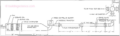
Figure 3: Air handling apparatus layout
Both the cooling and heating coils are flow controlled with electronic 3-way diverting valves. These valves are controlled through the data acquisition and control system with a 6 to 9 vdc input. The total flow through the two 62 watt (1/12 horsepower) circulating pumps is always contant and the valves simply divert the water proportionally to either the respective coil or back to the return line.
The next component is a steam distributor installed at the beginning of a 183 cm (6 foot) long duct to provide proper mixing of the steam and air. The steam distributor delivers steam to the air stream from 9 kg/hr (20 lb/hr) steam humidifier. Another 3-way diverting valve proportionally diverts steam to either the distributor or to an external condensing coil and condensate waste system. Condensate from three locations, the cooling coil, the steam distributor, and the steam diverting valve, flows to a condensate pump which pumps to a gavity drain.
Following the 183 cm (6 foot) long mising section is a direct-current blower connected to a variable-speed motor-controller. This system provides air flow control above the base air flow from the fan coil unit. The control feedback for the blower comes form a pressure transducer which measures the pressure differential across and orifice plate. The orifice plate was designed and constructed in house in accordance with the ASME Standard for Measurement of Fluid Fow (ASME, 1985).
The final component of the air delivery apparatus is a 4-way air diverter. This air diverter allows the automatic redirection of air to either end of the test section duct, enabling simulation of bi-directional air flow with the minimum number of air flow measurements and dampers. Conrol of the air diverter is provided by an electronic modutrol motor which operates on a 4 to 7 vdc signal.
Chilled and Hot Water Storage
The chilled water storage system consists of a 2-ton chiller, with a water cooled condenser, plumbed to two insulated storage tanks eah with their own circulation pump. The storage tank which services the top and bottom plate assemblies has a 151 liter (40 gallon) capacity. The tank which services the cooling coil in the air handling section has a 250 liter (66 gallon) capacity. Both circulation pumps are 30 watt (1/25 horsepower) and are used to continuously pump the tank water through the chiller. Temperature control of the chilled water is accomplished by adjusting the cut-in and cut-out pressure measured in the compressor suction line. Since the controlling adjustments are made at the chiller, both storage tanks are normally maintained at the same water temperature. However, it is possible to preferentailly cool the chilled water electronic 2-way proportional valve installed in the water supply line of the tank serving the cooling coil in the air delivery apparatus.
Hot water storage includes two 151 liter (40 gallon) insulated storage tanks. In order to keep the tanks well mixed, each tank has its own 30 watt (1/25 horsepower) circulating pump. One tank services the top and bottom plate assemblies and the other services the heating coil in the air handling section. Individual control of the hot water tank temperatures is accomplished through the use of optically isolated solid state relays. By controlling the temperature of the hot water tanks, it is possible to achieve much better control of both the air and plate temperatures. The solid state relays receive a control signal from the computer, thereby either blocking or passing the load current to the heater elements depending on the water temperature and the desired set point. The tank servicing the top and bottom plate assemblies has two 4500 watt heater elements, each in series with a 25 ampere solid state relay. The tank servicing the heating coil in the air handling section has two 2000 watt heater elements, each in series with a 10 ampere solid state relay. . .
Download complete document here.