A wall is supposed to keep the outside out and the inside in. That is the way things are supposed to work. Check out the “perfect wall” (Figure 1). We have our water control layer, our air control layer, our vapor control layer and our thermal control layer all in the right places. The wall dries outward from the vapor control layer and dries inward from the vapor control layer. All is right with the universe1.
The premise relating to the vapor control layer in the “perfect wall” is that it is for all intents and purposes completely impermeable—a true “vapor barrier”.2 That way “stuff” from the inside can’t get out and “stuff” from the outside can’t get in. By “getting out” we really mean getting into the wall from the inside and damaging it. By “getting in” we really mean getting into the wall from the outside and damaging it.
But do we even need the vapor control layer at all? Heresy. What if we took Figure 1 and turned it into Figure 2? Would it still be “perfect”? Yes, pretty much. Some folks have the audacity to say that it is even more “perfect”. A more “perfect” “perfect wall”? Perhaps. The premise now becomes instead of stopping “stuff” from getting into the wall from the inside let it go completely through the wall to the outside.
If “stuff” gets into the wall isn’t it better to let it get all the way out rather than kick it back in? Yes, I can live with that argument if the “stuff” actually makes it all the way “out”. How we let the “stuff” get out matters. If the “stuff” doesn’t get all the way out you shouldn’t let it get in or if it does get in you need to make sure bad stuff doesn’t happen like have it change phase or if it does you need to make sure you kick it back before it causes problems3.
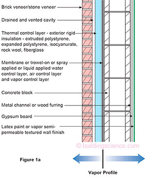
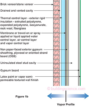
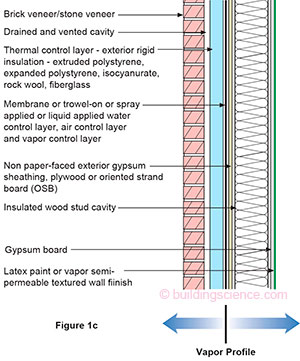
Figure 1: The “Perfect Wall”—We have our water control layer, our air control layer, our vapor control layer and our thermal control layer all in the right places. The wall dries outward from the vapor control layer and dries inward from the vapor control layer. All is right with the universe.
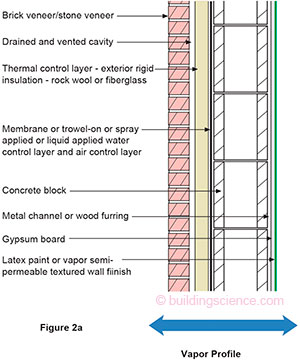

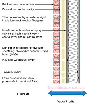
Figure 2: The More Perfect Perfect Wall? Can it be so easy that all we have to do to make the perfect wall more perfect is leave out the vapor control layer?
The “stuff” of course is water in one of its most tricky forms: “vapor”. But what about “stuff” from the outside? Yeah, that too. Rainwater getting in from the outside can be real trouble. Most of us believe that when this happens it is better for the assembly to be able to “dry” in both directions—so vapor barriers on the interior of wall assemblies that leak rainwater are a problem. Of course the easy answer to this is don’t have the wall assembly leak rainwater. Yeah. Right.
Can it be so easy that all we have to do to make the perfect wall more perfect is leave out the vapor control layer? Ah man, why do you ask these types of questions? Go irritate someone else. The answer is yes. Sorta. Kinda. But not always.4
When you have non-extreme environmental loads and continuous insulation on the outside. The answer is yes. What is a non-extreme environmental load? This means an enclosure enclosing an office or house or apartment rather than a natatorium, museum, hospital or art gallery5. So for natatoriums, museums, hospitals or art galleries stick with the perfect wall with a vapor control layer.
Not so fast. What does continuous insulation mean? Use the requirements in the International Energy Conservation Code (Table 1). Note that these are “conservative”. You could get away with less…but…following the table is easy because you don’t have to argue with the “authority having jurisdiction”. You want to argue? Okay, I like your attitude. If you go there you are going to need to do some convincing (see BSI-089: WUFI—Barking Up the Wrong Tree?). Here is a hint—don’t push the argument into “very cold” and “subarctic/arctic” climates (Figure 3).
Table 1: Ratio of Continuous Insulation to Cavity Insulation
IECC Climate Zone | Minimum Continuous Insulation/ |
4C | 15% |
4A, 4B | 20% |
5 | 30% |
6 | 35% |
7 | 45% |
8 | 50% |
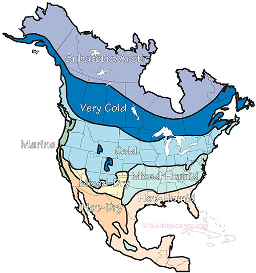
Figure 3: Hygrothermal Regions—Note that IECC Climate Zones 7 and 8 are considered “very cold” and “subarctic/arctic”.
What about when you have non-extreme environmental loads but you don’t have continuous insulation on the outside? It gets a little bit more restrictive. In cold climates you need some kind of interior “vapor throttle”. What is a cold climate? Think “Chicago” south and “Milwaukee” north as a kind of dividing line. The International Energy Conservation Code (IECC) is more specific. IECC Climate Zones 6 and higher require a vapor control layer. You can use a “smart” vapor barrier which is a type of “vapor throttle” and make a flow through assembly work without continuous insulation in these climate zones. But you need something to reduce the vapor flow rate from the interior if you do not have continuous insulation on the outside.
For all “flow-through” assemblies you need a ventilated cladding system over your continuous insulation or exterior sheathing to let moisture that is passing through the continuous insulation or sheathing and the respective water control layers and air control layers to get around the cladding. You don’t need much of a space for most claddings. I recommend a minimum of 3/8 inch (9.5 mm). We had this discussion before (see BSI-086: Vitruvius Does Veneers—Drilling Into Cavities).
When we get to reservoir claddings like brick veneers and very vapor open sheathings coupled with very vapor open water control layers and air control layers you need a bigger air space—1 inch (25 mm) for brick—and with stucco go with paint coupled with a drainage mat and the 3/8 inch. Again, we had this discussion before (see BSI-087: Chubby Checker and the “Fat Man” Do Permeance). Why a bigger air gap and why the paint? Ah, vapor can flow inward as well as outward. With a rain-wetted reservoir cladding coupled with incident solar radiation and air conditioning we get inward drive. We either have to throttle this inward drive down or we have to uncouple the cladding with a ventilated air space or we reduce the size of the reservoir by painting the cladding or by using additives that reduce water absorption. All of these approaches work.
Figure 4 shows the various configurations of flow-through assemblies. The “base” assembly is limited to IECC Climate Zones 5 and lower unless an interior vapor throttle such as a “smart vapor barrier” is used. The “rigid insulation” assembly and “multiple layers” assembly is constrained by Table 1.6 The “truss wall offset” and “double wall” need a mid assembly “throttle” in IECC Climate Zones 5 and higher (we have been here before, see BSI-087: Chubby Checker and the “Fat Man” Do Permeance).
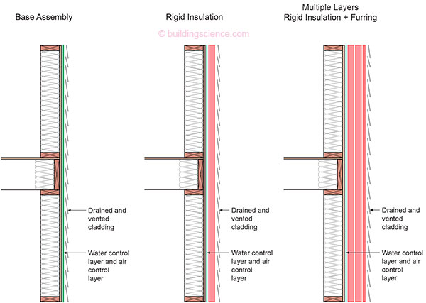
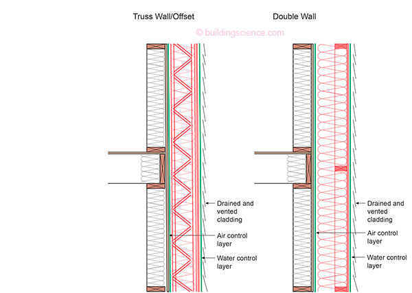
Figure 4: Flow-Through Assemblies—Various configurations of flow-through assemblies. The “base” assembly is limited to IECC Climate Zones 5 and lower unless an interior vapor throttle such as a “smart vapor barrier” is used. The “rigid insulation” assembly and “multiple layers” assembly are constrained by Table 1. The “truss wall offset” and “double wall” need a mid assembly “throttle” in IECC Climate Zones 5 and higher (we have been here before, see BSI-087: Chubby Checker and the “Fat Man” Do Permeance).
So how do these assemblies look like? They ought to look familiar (Photograph 1, Photograph 2 and Photograph 3). We sure have been building lots of them historically in places where it is not ugly cold in the winter. Most houses and office buildings have traditionally been “flow-through” assemblies with vapor permeable water control layers7 and no interior vapor barrier.
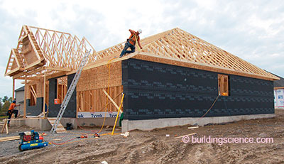
Photograph 1: Residential—Fully adhered vapor permeable water control layer and air control layer. Yes, one material or product can do both things. Note the now typical oriented strand board (OSB) sheathing—a semi-vapor permeable material—an “external vapor throttle”.
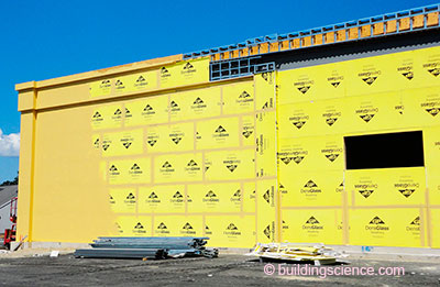
Photograph 2: Commercial/Retail—Fluid applied vapor permeable water control layer and air control layer installed over a vapor permeable glass faced gypsum board.
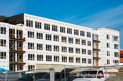
Photograph 3: Multifamily—Sheet vapor permeable water control layer and air control layer. The “classic” air infiltration barrier that also controls rainwater installed on the exterior of vapor permeable sheathing such as glass faced gypsum board.
The big change is Figure 5. We are beginning to see vapor permeable exterior rigid insulation—“continuous insulation” in the parlance of the model codes. The vapor “openness” of these rigid insulations allows us to extend “flow-through” assemblies to places where it actually is ugly cold in the winter.
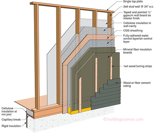
Figure 5: Vapor Permeable Exterior Rigid Insulation—We are beginning to see vapor permeable exterior rigid insulation—“continuous insulation” in the parlance of the model codes. The vapor “openness” of these rigid insulations allows us to extend “flow-through” assemblies to places where it actually is ugly cold in the winter.
Footnotes
- Our first column “BSI-001: The Perfect Wall”.
- Less than 0.1 perm (60 ng/(Pa-s-m2)), a Class I vapor retarder as defined by the model codes.
- Or “pull it” though sheathings or other layers in the liquid form quickly enough so it gets to the outside before it causes trouble on the inside. In the old days with plywood and fiberboard sheathings we would get frost and condensation on their interior surfaces but this change in phase from the vapor form to the liquid or solid form would not usually get us into trouble because the liquid phase water (or frost when it melted) would be wicked into the sheathings via capillarity where it typically got redistributed and eventually found its way to the outside surface where it could evaporate or diffuse to the exterior.
- Great “consultant” answer.
- These enclosures are typically operated at high interior humidities (50 percent or higher year round) and pressurized.
- It is not much of a constraint, but folks, at least look at the table just to make me happy? I am tired of listening to the “but I have a great ventilation system and no interior moisture “ argument. Remember that I am the guy folks call when things don’t work and I don’t like having to say “I told you so”.
- I never liked the term “wrb” or “water resistive barrier” or its even more annoying cousin “weather resistive barrier”. I grew up with “building papers”. Then they became “house wraps” except when they were “building wraps”. Now they are also called “combined air barrier wrb’s”. See BSI-024: Vocabulary.