This report describes the construction and instrumentation of Phase III of a multi-phase, multi-year research project at the Vancouver Field Exposure Test Facility in Coquitlam, British Columbia. Phase III focusses on the performance of various sheathings and claddings in a high stress moisture environment that is typical of the Pacific Northwest climate. The main research goal is to examine the performance of the various walls under the influence of intentional exterior wetting events in the drainage space.
Introduction
This multi-phase, multi-year research project at the Vancouver Field Exposure Test Facility in Coquitlam, British Columbia is led by Building Science Corporation (BSC) and Gauvin 2000 Construction Limited. This report describes the construction and instrumentation of Phase III of the research project1.
Phase III will demonstrate the performance of various sheathings and claddings in a high stress moisture environment that is typical of the Pacific Northwest climate. The main research goal is to examine the performance of the various walls under the influence of exterior intentional wetting events in the drainage space. The wall of specific interest is constructed with extruded polystyrene sheathing. As part of this multi-year test program, walls were subjected to normal interior and exterior stresses during the first year, high internal stress in the second year, and will see high external stress in the third year. The expected final deliverable will be a research report prepared at the conclusion of the Phase III testing2.
Background: Vancouver Field Exposure Facility
The test facility was constructed in the fall of 2005, in Coquitlam, British Columbia. The hut permits the side-by-side construction and comparison of seven 4’x8’ (1.2m x 2.4m) test wall panels on each cardinal orientation for a total of 28 wall test panels and three 12’ x 24’ (3.6m x 7.2m) roof panels on the north and south facing roof slopes for a total of six roof test panels. All of the test panels are exposed to the same indoor conditions. The objective of the initial test program was to determine the performance of historical, current and possible future wall assembly configurations under field conditions.
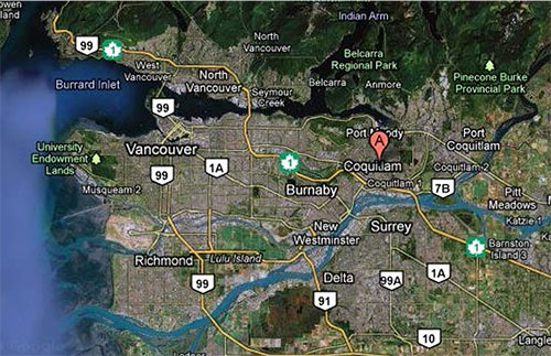
Figure 1: Test facility location in Coquitlam, British Columbia
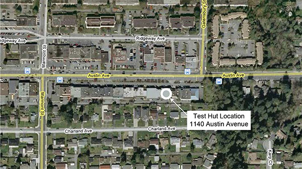
Figure 2: Test facility and immediate surroundings
The test facility was constructed on the roof of a low-rise office building, which is owned by Gauvin 2000 Construction (a British Columbia builder who is a co-sponsor of this research project). This eliminated the need to buy or rent a large empty site (with free wind approach) in the expensive real estate market of greater Vancouver. It also affords the test facility some protection from potential vandals. Figure 3 and Figure 4 show elevation drawings of the test facility.
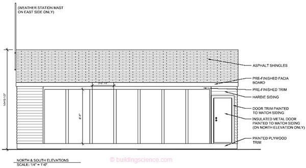
Figure 3: North and south elevation
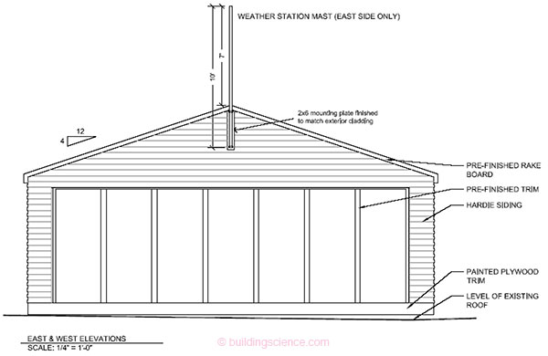
Figure 4: East and west elevation
A steel mast on the roof of the test facility supports a weather station at a height of 22 ft (6.7 m) above the roof of the office building and 50 ft (15.2 m) above ground level. The monitoring system continuously collects weather data including temperature, relative humidity, wind speed and direction, rain, and solar energy.
Phase III Construction and Instrumentation
This is the third phase of testing completed at the Coquitlam test facility. The Phase II walls were deconstructed and removed to ensure that the effects from Phase II testing do not affect Phase III testing and observations. This phase will utilize wetting apparatuses on both the interior and the exterior of the exterior wood sheathing. The Phase III walls were built and installed by Gauvin 2000 Construction and instrumented by BSC staff during the week of November 2nd, 2009. Installation of the insulation and finishes continued until late November and the final programming was completed by BSC in early December.
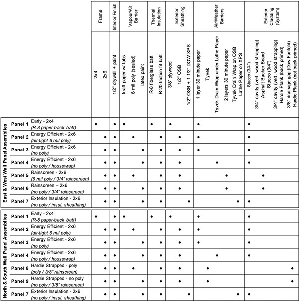
Table 1 lists the test walls along with the materials used. Some of the wall test panel assemblies were chosen to represent conventional construction practices from the past 40 years while others are designed to investigate the role of specific layers, and to test possible products and systems.
Table 1: Wall construction details
Each of the test walls was outfitted with a series of temperature (T), relative humidity (RH) and wood moisture content (MC) sensors. These sensors will continuously monitor and record to the data acquisition system throughout the testing period. All walls received a similar sensor package. This package is illustrated in Figure 5.
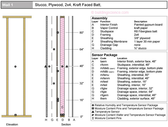
Figure 5: Typical instrumentation package
Moisture content pins were installed in the framing lumber and the sheathing in all wall systems. Wood moisture contents can be determined from the electrical resistance of wood based on the Garrahan equation. These pins can be used to measure moisture content at any depth because the pins are electrically insulated except for the tip. Measurements are most commonly taken at ¼” or 6mm in depth. With the exterior wetting systems introduced in Phase II, a double set of moisture pins were used. One set was at the standard depth to measure the MC of the interior face of the sheathing and one set was set deep to measure the exterior face MC of the sheathing. The wood moisture content pins were installed in combination with a temperature sensor in all locations. The temperature sensor was drilled to the depth of the moisture content pins and the temperature readings are used to correct the wood moisture content readings.
Relative humidity sensors were always installed in combination with temperature sensors, both of which were protected by a vapor permeable, water resistant cover. Relative humidity and temperature sensors were installed at the midpoint of the stud space, between the drywall and the sheathing, behind the drainage material at two heights and outboard of the drainage material at mid-height.
Example photographs of the individual sensors are shown below in Figure 6 to Figure 11.
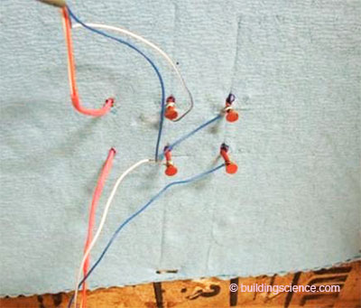
Figure 6: Interior and exterior sheathing MC/T sensors
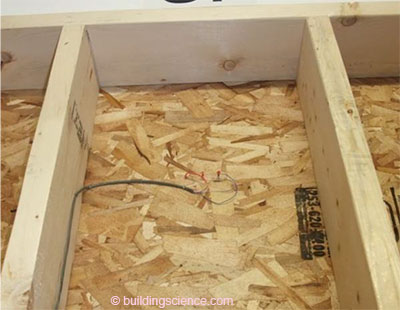
Figure 7: Upper interior sheathing MC/T sensors . . .
Download complete report here.
Footnotes:
- This report was written prior to the completion of Phase III, which ran from December 17, 2009 to November 3, 2011. It is provided for reference. For current information about the Vancouver Test Hut Project, see www.buildingscience.com/documents/special/vancouver-test-hut.
- Smegal et al, RR-1207: Vancouver Field Exposure Facility: Phase III Exterior Insulation Analysis, available at www.buildingscience.com/documents/reports/rr-1207-vancouver-field-exposure-facility.