Using diagnostic tools to find air leaks that make homes inefficient, uncomfortable, and are often the cause of moisture-related problems.
Introduction
The work I do for Building Science Corporation (Joe Lstiburek’s company, for those who don’t know) involves forensic investigations of moisture-related (or similar) building failures—i.e., sleuthing out problem buildings. Despite the fancy name, this typically involves crawling around the bowels of commercial and residential buildings to look at the problem areas and figure them out. They range from sleuthing out strange odors that seem to emanate out of nowhere, windows that leak water during rainstorms, indoor swimming pools with rotting walls, freezer warehouse buildings with icicles growing out of the ceiling, mega-mansions with out-of-control humidity levels that are damaging the art collection, and moldy and wet crawl spaces.
To solve these problems, a set of eyes and an understanding of building physics are the most important tools. But there are many clues that are not visible—thus the use of building diagnostic tools: the focus of this column. This series will cover a selection of my go-to tools for this type of building science diagnostic work. I’m not pretending this is a comprehensive survey of the available tools—but they are my go-to items in day-to-day investigations. Also, I am deeply indebted to all of the other practitioners who have shared their knowledge, instruments, and tips/tricks—I can only hope I’m doing a little bit to pay it forward here.
The structure for these columns will be broken down roughly into the following topics:
- Part 1: Air. Devices that measure air leakage (such as Blower Doors™ and Duct Blasters®), differential pressures, and airflow.
- Part 2: Heat. Infrared cameras, temperature meters, thermal bridges… and when combined with airflow tools, finding air leaks
- Part 3: Water. Moisture meters, water testing windows, demonstrating drip edges and slope with squirt bottles
Why Air Measurements are Important
Controlling the air inside the building—by limiting air leakage—is critical for conditioning the air, and therefore affects comfort and energy use in buildings. But in addition to carrying heat, air leakage often carries moisture with it: this can lead to a variety of durability problems. Examples of air leakage problems include growing mold on roof or wall sheathing due to outward air leakage in cold climates, or condensation on cold ducts or pipes due to inward air leakage in hot-humid climates. In addition, I’m seeing more and more indoor humidity problems up and down the East Coast, and air leaks are a part of them. When I hear folks complaining about “new buildings being too airtight,” I let them know that I’ve investigated far more problem buildings that were too air leaky rather than too tight.
Of course, air is invisible—although you can feel it moving from one place to another, instrumentation can tell you a lot more.
Air Leakage Testing
A blower door (Minneapolis Blower Door™) is a calibrated fan used to measure air leakage in buildings; it is typically installed in a fabric shroud mounted in a doorway (Figure 1). The fan is used to depressurize the building to a known test pressure (typically 50 Pascals), and the airflow (cubic feet per minute or CFM) required to reach that pressure is a measurement of the building’s total air leakage (reported as “CFM at 50 Pascals” or “CFM 50”). Current codes require airtightness testing; this equipment is used for both houses and large commercial buildings (although more fans are needed).
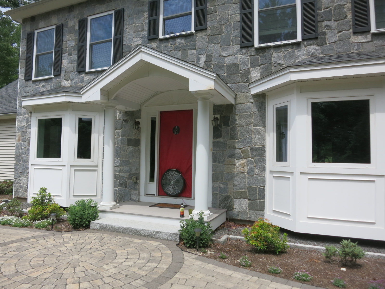
Figure 1: Testing a house with a blower door
Duct testing equipment (e.g., Duct Blasters®) is used in a similar manner to test duct airtightness. The calibrated fan is connected to a ductwork system, the intentional holes (i.e., registers and grilles) are sealed, and the airflow required to reach a test pressure provides a measurement of leakiness.
This is not intended as a full discussion on the basics of measuring air leakage and how to use the equipment: manufacturers such as the Energy Conservatory and Retrotec have a wealth of information—including great instructional videos found here and here respectively.
Incidentally, Duct Blasters® are useful for more than ductwork testing. They can also be used to test airtightness of small buildings (such as the cottage in Figure 2), very airtight buildings, or individual dwelling units in multifamily buildings. For reference, Duct Blasters® can test up to 1350 CFM 50, while a Minneapolis Blower Door™ maxes out at 5350 CFM 50.
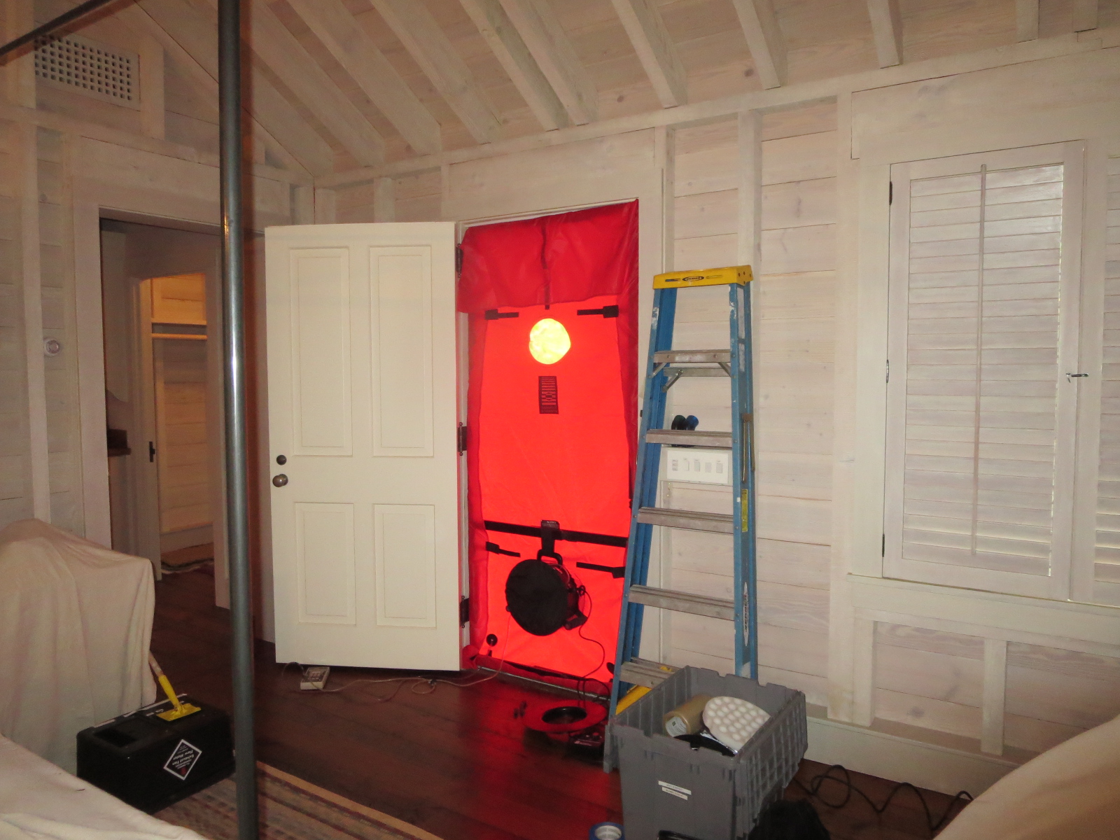
Figure 2: Testing a cottage with a Duct Blaster®
Blower Doors and Pressure Difference Measurements
In addition to testing the overall building’s air leakage, we can use this equipment to create pressures in a building, and learn more about leaks in certain areas or zones. For instance, conditioned/unvented attics (with insulation and the line of airtightness at the roofline), are becoming more common, to keep ductwork within the conditioned space and to insulate complicated rooflines. When testing these buildings for airtightness, we often measure the pressure difference (or ΔP/ “delta P”) across the attic hatch.
The ideal condition is shown in Figure 3 with the house at -50 Pascals (Pa) relative to outdoors, if the ΔP across the hatch is 0 Pa, it means that the attic is also at -50 Pa. This indicates that the attic is 100% “inside”—the depressurization of the main portion of the house extends up into the attic, and it is all operating as a single zone of air.
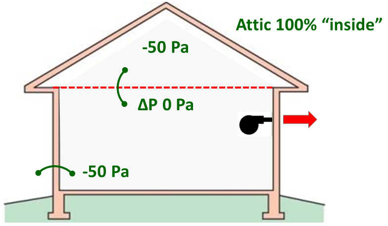
Figure 3: Depressurized house with an unvented/conditioned attic, 0 Pascals across ceiling (good)
A similar measurement is shown for a vented (unconditioned) attic in Figure 4; in this case, the attic is intentionally connected to outdoors with low and high vents, and we want the ceiling plane to be as airtight as possible. With the house at -50 Pa relative to outdoors, if the ΔP across the hatch is also 50 Pa, it means the attic is at 0 Pa—i.e., the same pressure as outdoors. This suggests the attic is well-vented and/or the ceiling plane is relatively airtight—all excellent for performance.
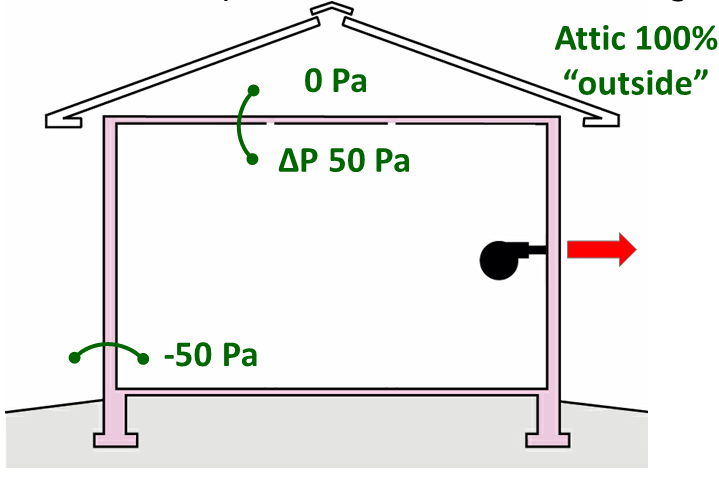
Figure 4: Depressurized house with a vented/unconditioned attic, 50 Pascals across ceiling (good)
But most of the time, we see conditions other than these two extremes. For instance, take that same unvented attic we looked at in Figure 3. If we ran the house at -50 Pa relative to outdoors, and the pressure difference across the hatch was 25 Pa (Figure 5), it means that the attic is at -25 Pa. This indicates that the attic is “halfway” between inside and outside. In more precise language, it means that the area of the holes in the roof (from attic to outdoors) is equal to the area of the holes in the ceiling (attic to house).
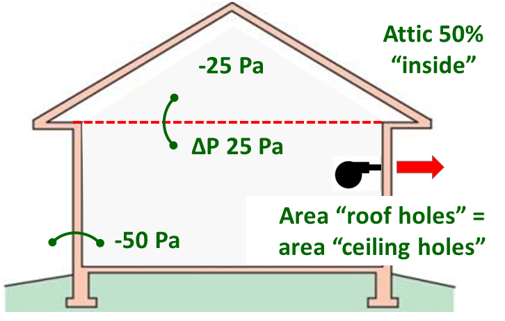
Figure 5: Depressurized house with a conditioned attic, 25 Pascals across ceiling (not good)
Typically, this is a problem: it suggests that there are big air leaks from the unvented attic to outdoors that we need to fix, given that the ceiling plane is usually not intentionally air sealed in these houses. This usually involves crawling around the attic looking for signs of air leakage. Also, the amount of airflow coming down through the hatch can give you a first gut feel on how an unvented attic is performing—the ideal situation is next to no air from opening the hatch, and the worst case is a gusher of air.
Another example of this technique is shown in Figure 6 during a depressurization blower door test, we taped off the fireplaces with cardboard to avoid sucking ash into the house. Measuring the pressure drop or ΔP across the cardboard showed that the dampers are not really doing much air sealing, and that the fireboxes were essentially outside. This contributed to the major summertime air leakage in this house, and resulting problems keeping interior humidity under control.
In Figures 6-10, I’m using the Energy Conservatory DG-700 Pressure and Flow Gauge. It has since been discontinued. The new model is the DG-1000 Digital Pressure and Flow Gauge. We haven’t upgraded to the DG-1000 yet, but they’ve been out for a while, and well, work.

Figure 6: Measuring ΔP across a fireplace seal
Figure 7 shows a ΔP measurement at a party wall in a multifamily building—these “burn away” walls are notoriously difficult to air seal and a problem for getting these buildings airtight. By removing the outlet cover plate and measuring the ΔP across the drywall, we could figure out the problem areas at the party wall, which ended up being the garage connection and the HVAC closet.
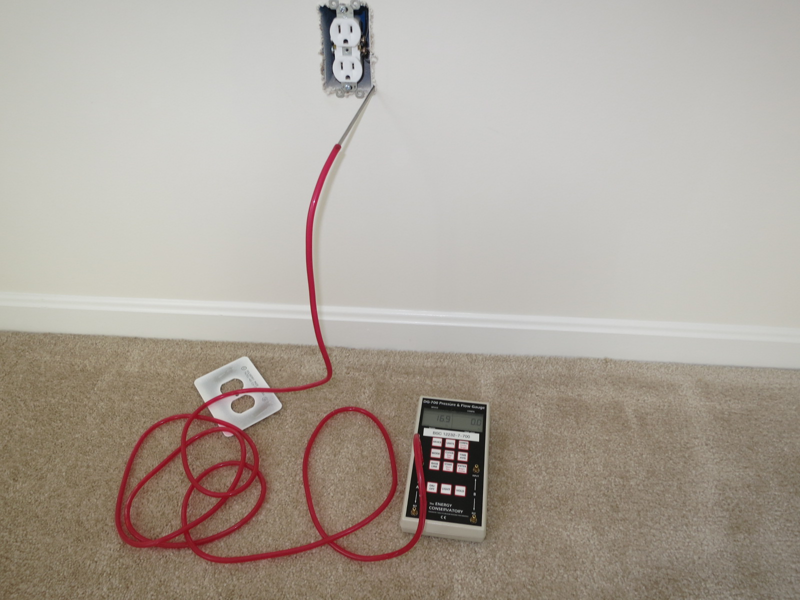
Figure 7: Measuring ΔP at an electrical outlet
There is an entire set of techniques for using these types of ΔP or “differential pressure” measurements, called zone pressure diagnostics (for instance, see here), but that’s beyond what we can cover here.
Indoor-Outdoor Pressure Measurements
Air pressures define which way the air moves, and how quickly. Therefore, measuring air pressures during normal building operation can also provide clues to problem conditions. For instance, in southern climates, “buildings that suck” can lead to huge moisture problems from pulling in hot, humid outdoor air.
It’s also useful to have a bit more of an intuitive understanding of the pressure measurement of Pascals/Pa that we use. It is a very small unit—one Pascal is about the weight of a fly on the area of a penny. Also, 1 psi is 6895 Pa. Correctly-operating houses normally operate in the 3-5 Pa range, the blower door and duct blaster tests are run at 50 Pa and 25 Pa respectively, and when buildings are pressurized to exclude contaminants, 10-12 Pa is a typical range.
When I deal with commercial building facilities managers and ask them whether their building is running at a positive or negative pressure, they sometimes respond, “they added up the airflows and it should be positive.” My response is: let’s measure it directly to figure it out—and plenty of times, adding up the airflows gives the wrong answer. Indoor-outdoor pressure measurements are simple if you can find an operable window or doorway.
These ΔP measurements are also important for residential work—for instance, if they installed an oversized kitchen range hood in a custom house without a makeup air system, we can measure the net effect. Also, very airtight construction with unbalanced fans (e.g., exhaust-only ventilation) can cause problems. Figure 8 and Figure 9 show measurements of indoor-outdoor ΔP at a door or window. Before anyone gives me grief about the daylight you can see at the window sill, that only affects the ΔP measurement if a house is very airtight, and doesn’t matter for most of these types of measurements.

Figure 8: Indoor-outdoor ΔP at a doorway
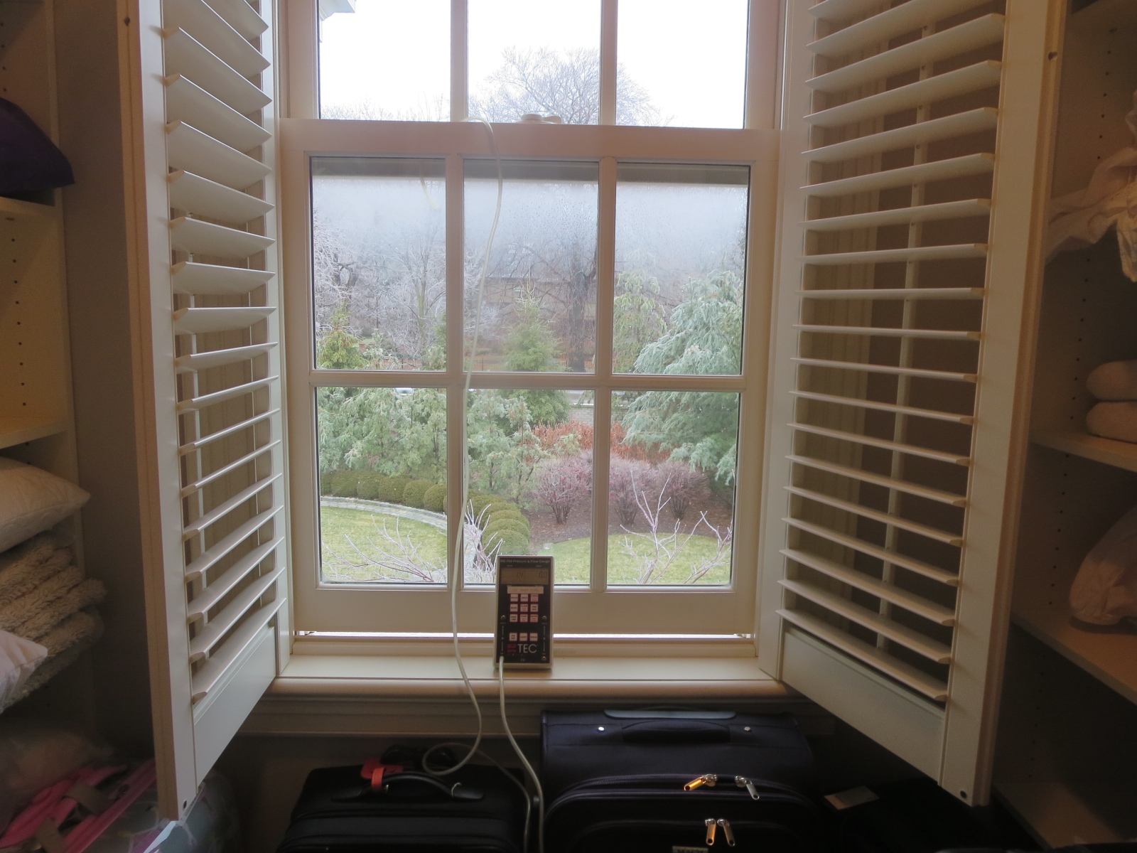
Figure 9: Indoor-outdoor ΔP at a window
But there are times when a one-time measurement isn’t enough to fully understand what is going on. For instance, on a windy day, it can be next to impossible to tease out the effect of operating fans on house pressures. Also, it can be useful to get a log of operating many mechanical systems (kitchen exhaust, bath exhaust, dryer) in various combinations to determine their effect.
In those cases, you can connect Energy Conservatory manometers (pressure meters) to a computer (Figure 10) and use free software (TECLOG) to graph the pressures in real time, and to observe the effect of changes visually (Figure11). This creates a computer file that you can refer to and run calculations on later.

Figure 10: Using TECLOG to log pressures
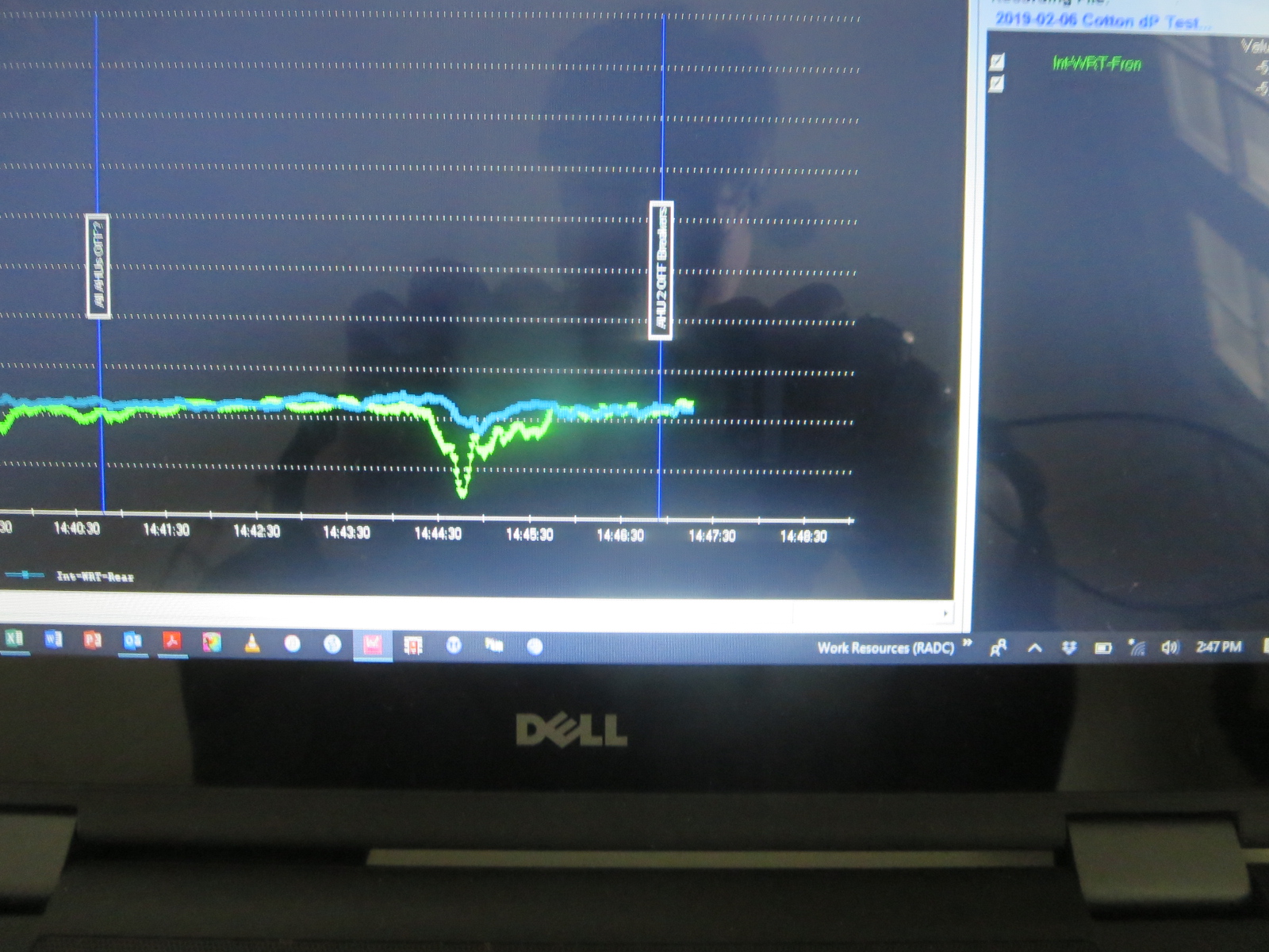
Figure 11: TECLOG real-time pressure graph
Air Flow Indication and Measurement
In addition to putting a number on pressure differences, it’s often useful to demonstrate where air leaks are, and which way airflow is going. The typical go-to solution is a smoke generator or a smoke pencil—one trick from my colleagues is to connect a vaping pen to a squeeze bulb (Figure 12). I have also heard good things about Cirrus Outdoors smoke generators (https://www.cirrusoutdoors.com/), but haven’t tried one myself.

Figure 12: Smoke pencil from a vaping pen
To get more precise, wind or air velocity meters (such as Kestrel impeller-based meters, Figure 13) can measure these flows—typically in feet per minute/FPM. You can estimate flows out of HVAC registers by measuring airspeeds and the opening area (called a “traverse”) with these meters.

Figure 13: Kestrel wind (air velocity) meter
However, I’ve pretty much replaced my Kestrel meter with a tool from the HVAC world—a hot wire anemometer (Figure 14 and Figure 15, Fieldpiece Instruments STA2 In Duct Hot-wire Anemometer). A hot wire anemometer has a fine wire that is heated above air temperature, and the rate of heat loss/cooling measures the airspeed. This tool is exceptionally useful because it has an extension probe that lets me “feel” for air leaks out of arm’s reach. A typical use is to depressurize the building, and put the probe on suspected air leakage locations. Figure 14 is the inside of a metal panel building—this panel seam was leaking despite the double-gasket design. Figure 15 shows measurements of air leaks around a window sill with the trim removed: hot, humid air was getting pulled from the masonry cavity at these openings under the window trim and condensing/dripping.
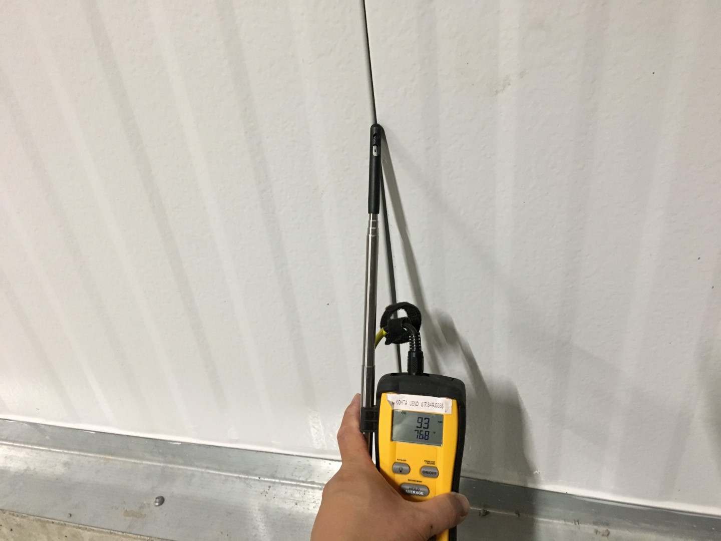
Figure 14: Hot-wire anemometer air velocity meter
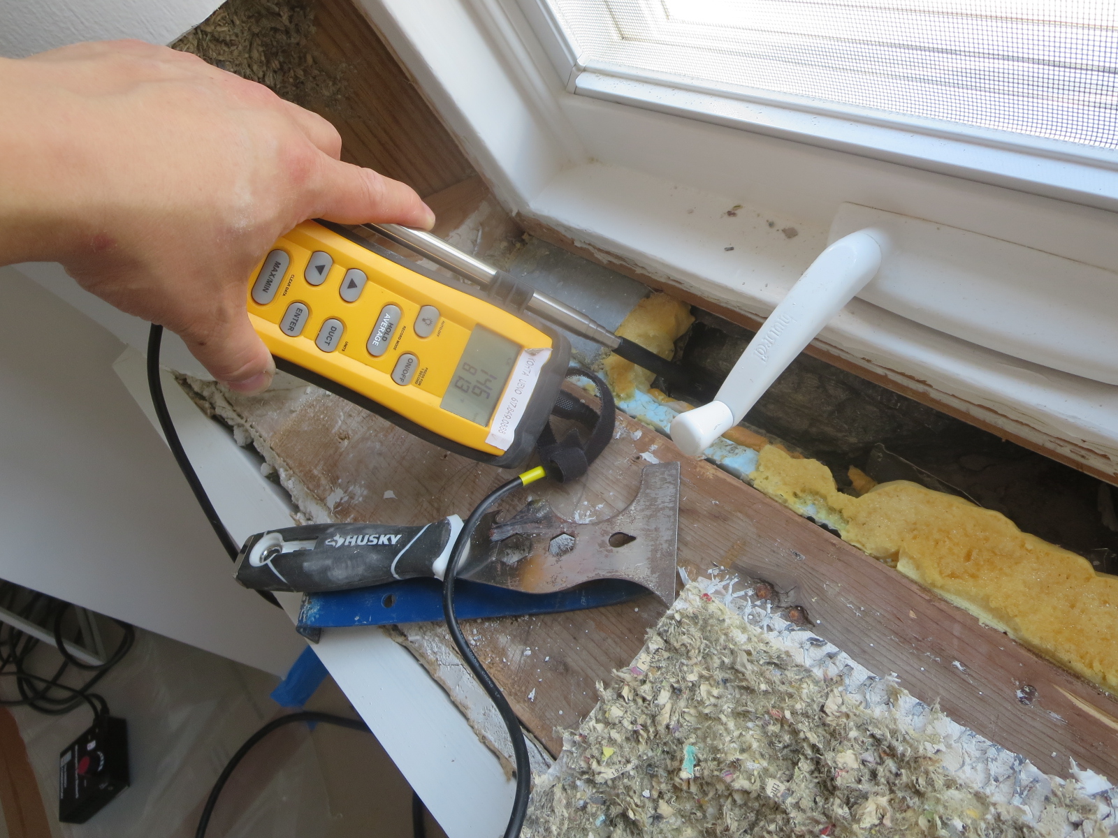
Figure 15: Hot-wire anemometer air velocity meter
HVAC Air Flow Measurements
Getting more into the HVAC world, measuring airflows into grilles/exhausts and out of registers/supplies is often useful, especially when doing commissioning (or startup) measurements—is your equipment providing the flow that they said it would? Also, these tools come out when we’re trying to diagnose HVAC-related problems, like hot or cold rooms.
The equipment that an HVAC technician would use is a flow capture hood (Figure16)—it can be used for either supplies or returns (up to a limited size). As a warning, there are plenty of case studies showing that you get wonky results with problems like off-center placement, a register that “swirls” the airflow, or even their effect of “choking off” the airflow by putting the flow hood on the register (see “How Accurate is Your Air Flow Capture Hood Measurement")

Figure 16: Flow capture hood
A useful tool for exhaust fans is a “flow box” (Energy Conservatory Exhaust Fan Flow Meter, Figure 17)—it’s a box with a variable opening, and measuring the pressure inside the box provides the exhaust flow. Light, quick, reliable, and works well. Lastly, if you’re looking at exhausts, the “toilet paper test”—despite its simplicity—gives some useful information. If the toilet paper sticks to the fan face, you’re probably getting a decent airflow.
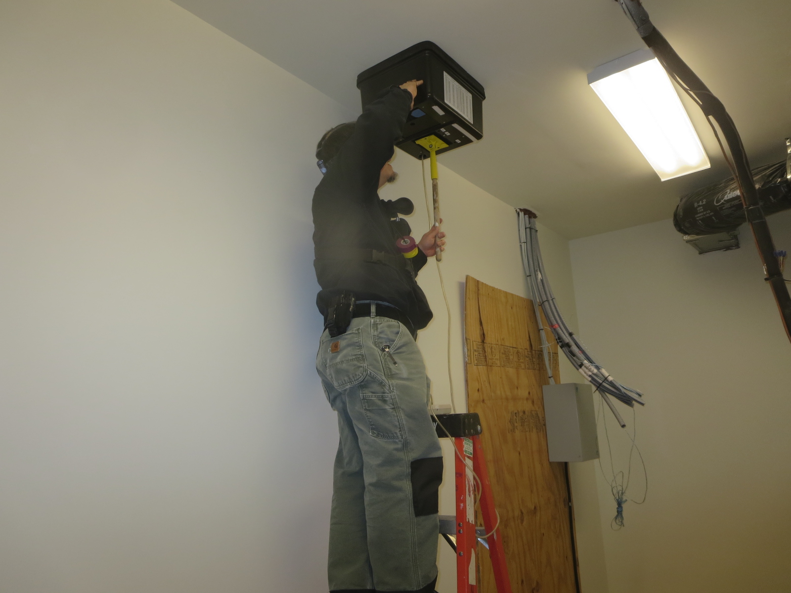
Figure 17: Exhaust fan flow meter