OVERVIEW
Spray foam insulation has significant advantages over other insulation systems due to the spray foam ability to provide continuity of the water control, air control, vapor control and thermal control layers necessary for environmental separation. Using spray foam results in low exterior air leakage that provides significant energy efficiency and significant sound attenuation. Using spray foam results in excellent vapor control and thermal efficiency.
Spray polyurethane foam (SPF) – high density closed cell - is the only product that can perform all of the functions of the principal control layers of the “Perfect Wall” namely:
The water control layer
The air control layer
The vapor control layer
The thermal control layer
Figure 1 and Figure 2 illustrate the typical configuration. The high density closed cell spray foam should be sprayed directly on the block wall or directly on the exterior sheathing. An intervening additional water control layer should not be installed as it interferes with the bonding of the high density closed cell spray foam to the substrate. The spray foam is the water control layer.
The steel stud cavity in Figure 2 can be insulated acoustically with low density open cell spray foam or with fiberglass or cellulose. High density closed cell spray foam should not be used for acoustical purposes.
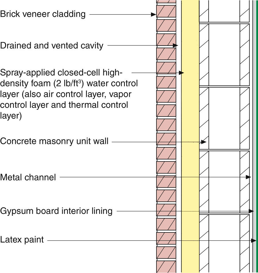
Figure 1: Concrete Masonry Wall – Spray-applied closed-cell high-density foam is the water control layer, the air control layer, the vapor control layer and the thermal control layer. The high density closed cell spray foam should be sprayed directly on the block wall. An intervening additional water control layer should not be installed as it interferes with the bonding of the high density closed cell spray foam to the substrate. The spray foam is the water control layer.
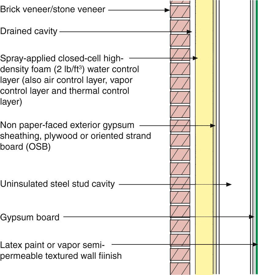
Figure 2: Steel Stud Wall – Spray-applied closed-cell high-density foam is the water control layer, the air control layer, the vapor control layer and the thermal control layer. The high density closed cell spray foam should be sprayed directly on the exterior sheathing. An intervening additional water control layer should not be installed as it interferes with the bonding of the high density closed cell spray foam to the substrate. The spray foam is the water control layer. The steel stud cavity can be insulated acoustically with low density open cell spray foam or with fiberglass or cellulose. High density closed cell spray foam should not be used for acoustical purposes.
WINDOW INSTALLATION
Do not spray the SPF to the windows. A transition assembly between the glazing systems and the wall assembly is required. The concept of an extended “buck” is recommended (Figure 3 and Figure 4 for masonry back-up walls and Figure 5 and Figure 6 for steel stud back-up walls). Notice the plywood or OSB “lip” and the use of a liquid applied flashing membrane to provide a drained opening – an under window “gutter” that directs water to the outside face of the SPF should the window assembly leak. This approach allows standard window installation approaches to be used. Also notice how the membrane extends around the opening onto the face of the masonry back-up wall or on the face of the sheathing over the steel stud back-up wall. This is called “raccooning” – after the eyes of a raccoon. With this approach the windows can be installed either before or after the application of the SPF.
Notice in the images the use of “grey” shading to “define” a spray foam “filet”? Upon application SPF tends to pull away from some surfaces – shrinkage is a term sometimes used. To prevent a gap from opening up between the edge of the extended buck and the SPF the perimeter of the opening is “picture framed” with SPF in a “filet” shape/geometry. Then the field of the wall is sprayed.
This is important at the tops of windows because if you don’t do it the flashings can be pulled upwards resulting in a negative slope on the flashings. All flashing, not just window flashing should have the “filet” treatment first before the field of the wall gets sprayed.
Treat door openings the same way.
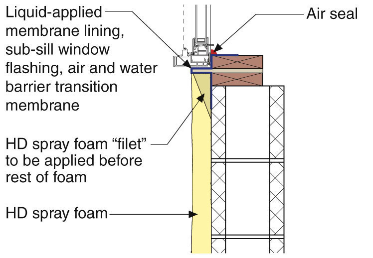
Figure 3: Masonry Wall Sill Detail – Wood buck with plywood or OSB lip creates under window gutter. Note the foam “filet” picture framing the opening.
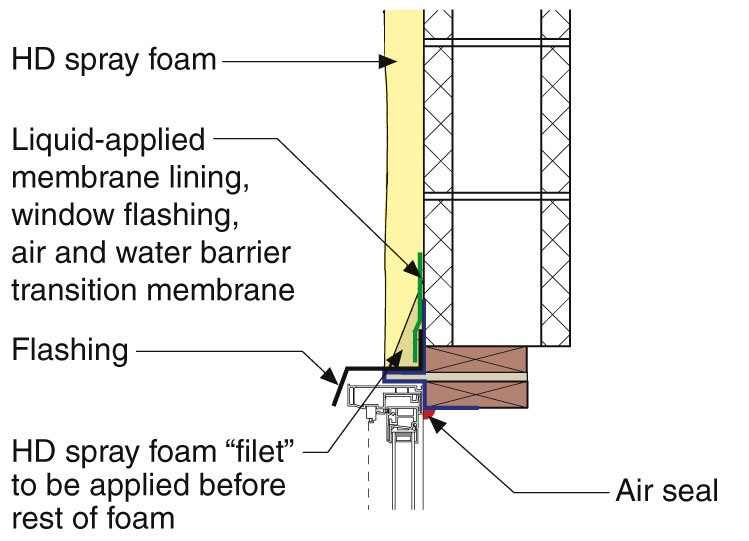
Figure 4: Masonry Wall Head Detail - The foam “filet” is sprayed first to prevent the head flashing from being pulled upward leading to a negative slope.
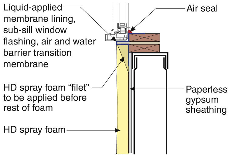
Figure 5: Steel Frame Wall Sill Detail – Note the importance of the foam “filet”.
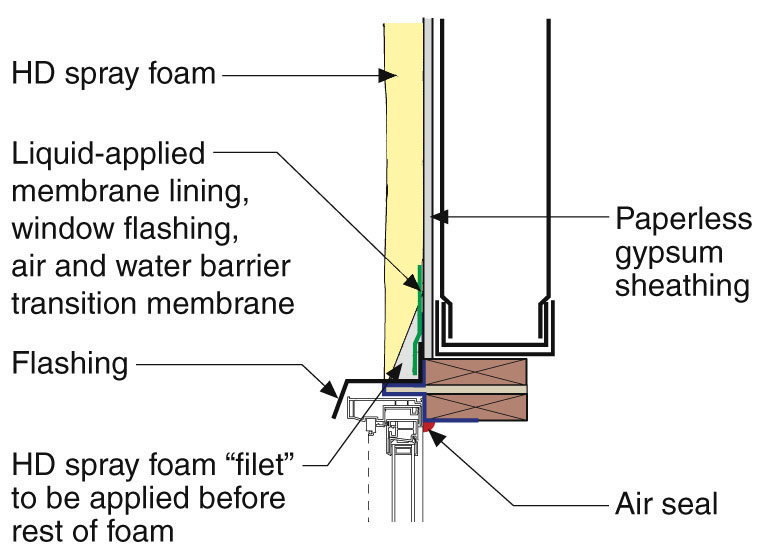
Figure 6: Steel Frame Wall Head Detail - Negative slopes on flashing should be avoided.
FRAME MOVEMENT
Concrete frame buildings shrink over time (Figure 7). This is often referred to as “creep” or “frame-shortening” is used. It is common for “relieving angles” and “soft” joints to be used to address frame movement (Figure 8 and Figure 9) and the concept of the “nested” track in Figure 10. The relieving angle is shown in Figure 11. Also note how the relieving angle is held away from the wall on brackets (or “stand-offs”) to control thermal bridging.
Buildings also move from side to side and vertical control joints are also necessary (Figure 12 and Figure 13).
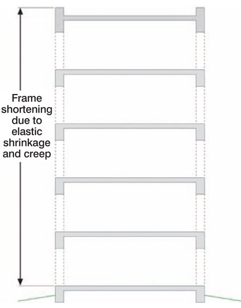
Figure 7: Frame Shortening or Creep
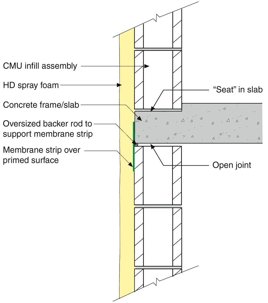
Figure 8: Masonry Soft Joint – Notice the gap. Also, note the “seat” in the slab to deal with incidental rainwater leakage.
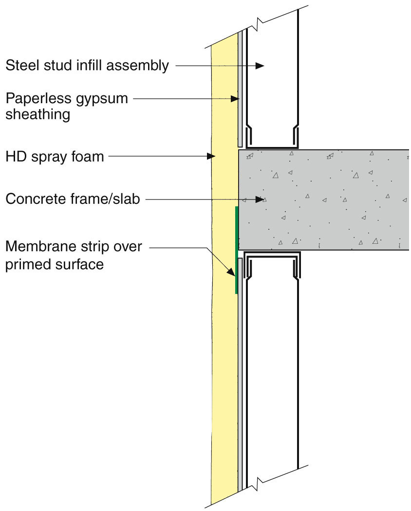
Figure 9: Steel Frame Soft Joint – Note the “nested” track for the steel frame.
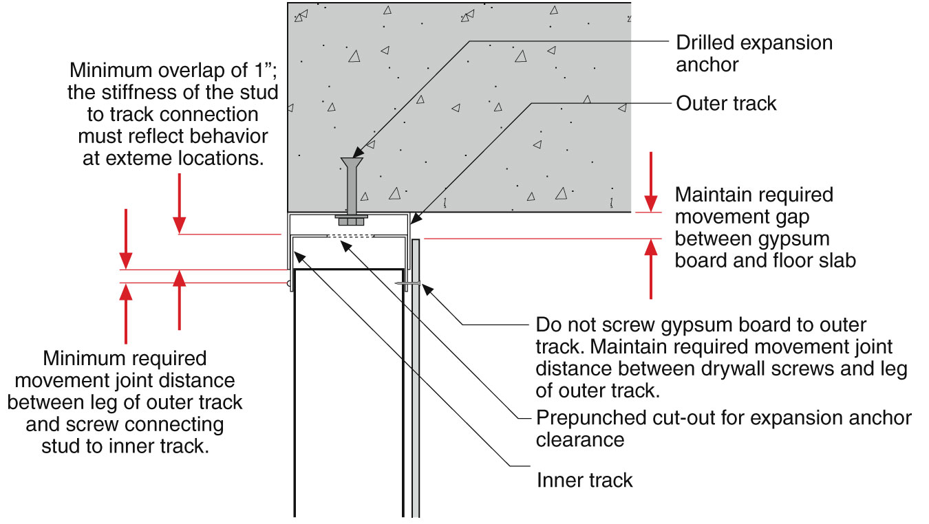
Figure 10: Nested Track – Allows for movement.
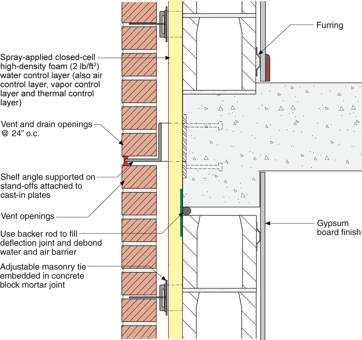
Figure 11: Stand-Offs For Relieving Angle – Thermal bridging is controlled as well as frame shortening along with water, air and vapor.
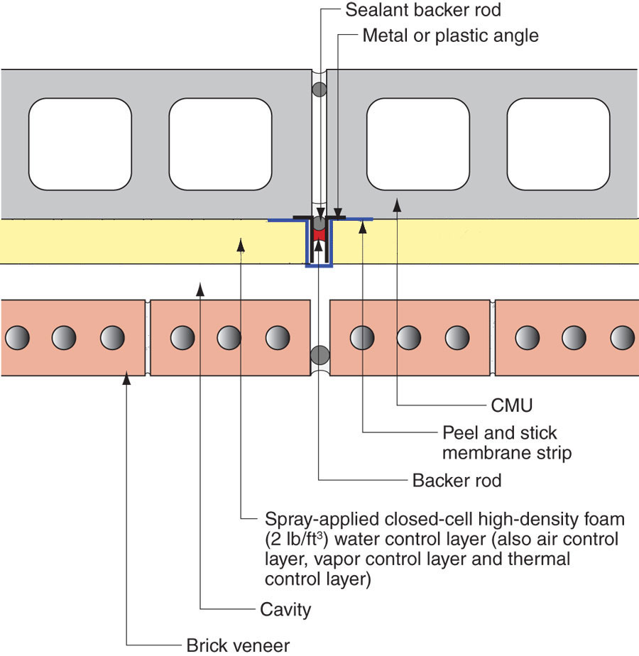
Figure 12: Vertical Control Joint – Control joint in back up wall and cladding.
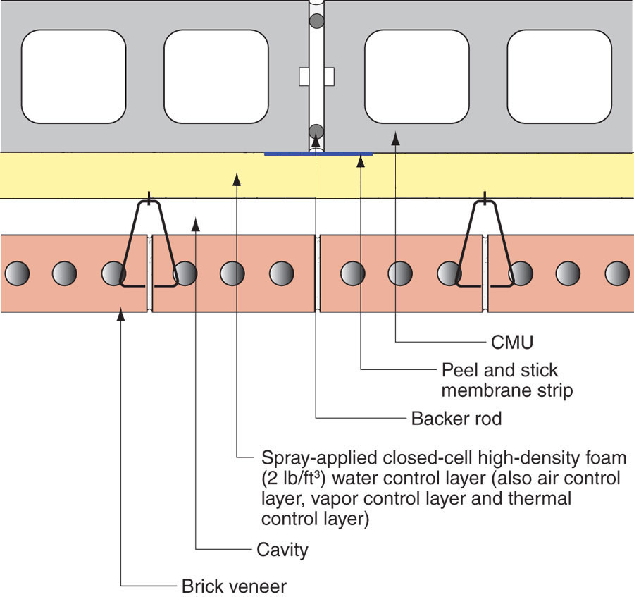
Figure 13: Vertical Control Joint – Control joint only in back up wall.
CLADDING ATTACHMENT
SPF does not go on completely smooth and flat and of uniform thickness. With brick veneers that is not an issue due to the air gap behind brick.
Attaching panel cladding through SPF requires “straight” and “planar” purlins or girts. The key is to minimize thermal bridging. Using a metal Z-bar typically results in thermal bridging (Figure 14). A “stand-off” approach is recommended to address the conductivity of metal Z-bars. Long screws in a “spacer sleeve” can be used (Figure 15). The compressive strength of the SPF addresses the issue of screw bending – the “bending moment” of the screw. For the screw to bend it has to rotate inward into the wall. For it to rotate inward into the wall the girt or purlin has to rotate with it. The compressive strength of the SPF resists the inward rotation (Figure 16 and Figure 17). Structurally, this can be calculated as a “truss”. When the SPF is applied the foam expands outward and bonds to the frames stiffening the assembly.
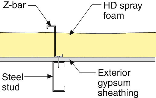
Figure 14: Z-Bar Thermal Bridge – Not energy efficient.
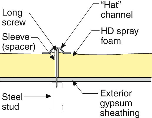
Figure 15: Hat Channel Stand-Off – Energy efficient.
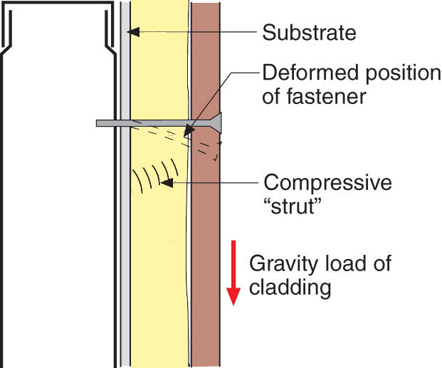
Figure 16: Inward Rotation Resistance - For the screw to bend it has to rotate inward into the wall. For it to rotate inward into the wall the girt or purlin has to rotate with it. The compressive strength of the SPF resists the inward rotation.
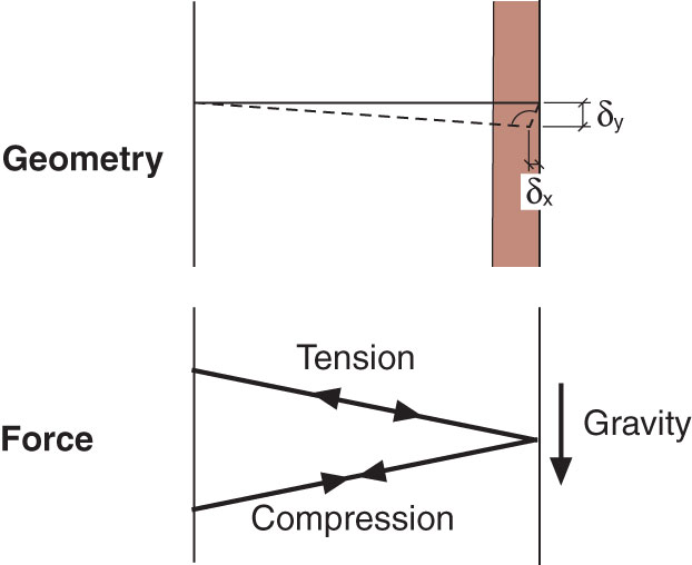
Figure 17: Truss Analogy - Structurally, this can be calculated as a “truss.
WALL TO ROOF CONTROL LAYER CONTINUITY
It is necessary to connect the water, air, vapor and thermal control functions of the wall SPF to the corresponding water, air, vapor and thermal control functions of commercial roof assemblies (Figure 18, Figure 19, Figure 20 and Figure 21).
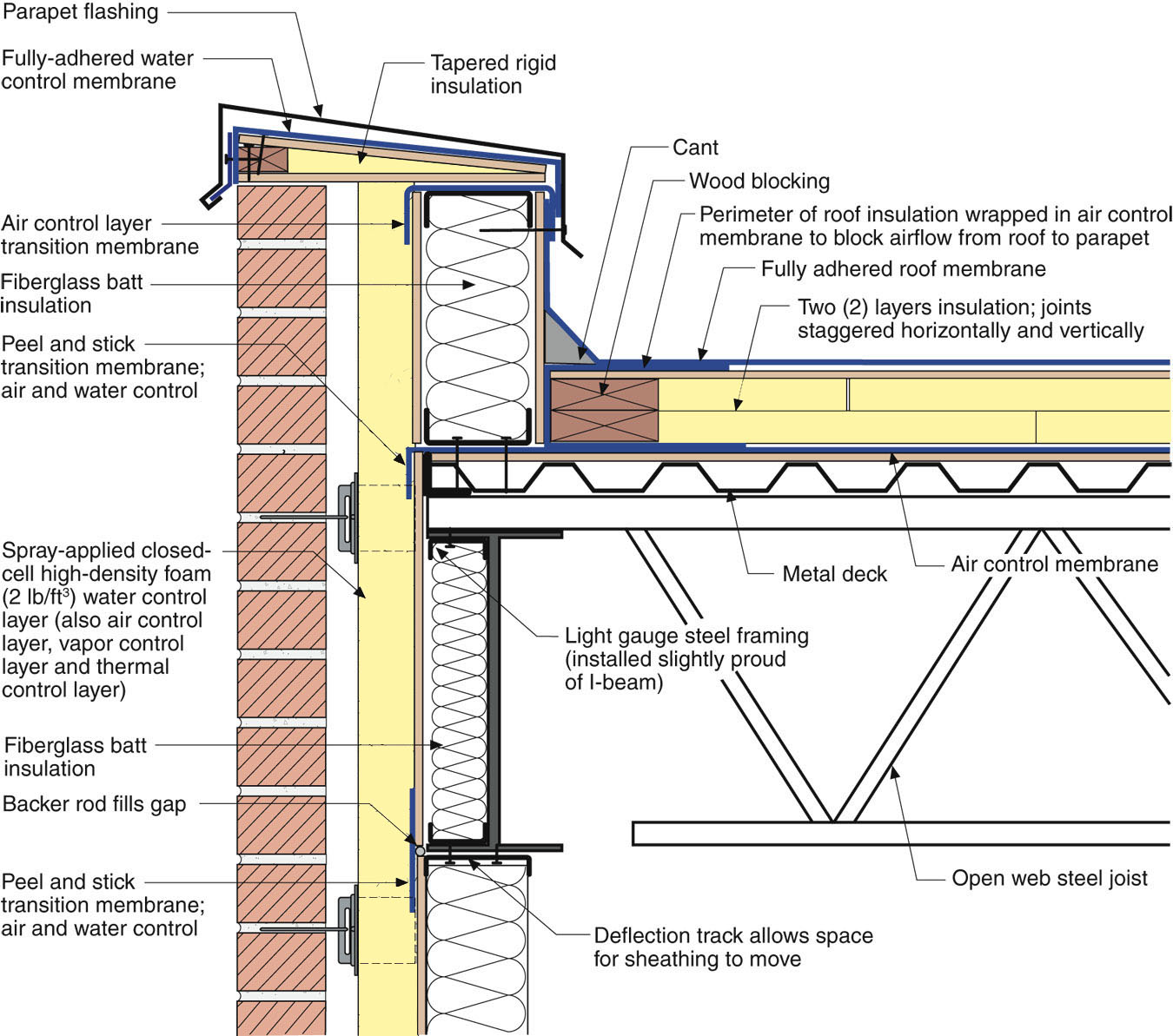
Figure 18: Parapet Control Layer Continuity – Steel stud to steel roof.
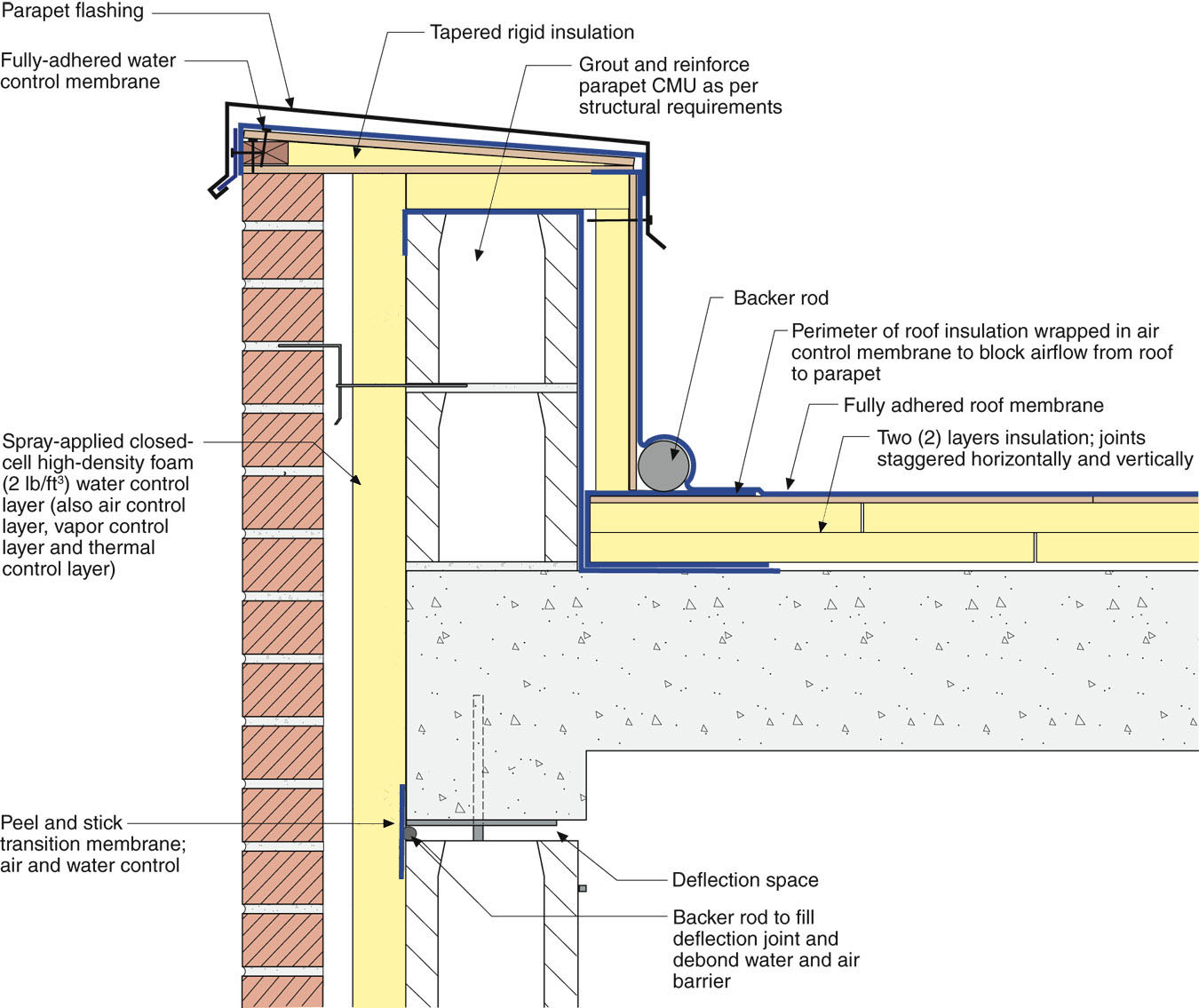
Figure 19: Parapet Control Layer Continuity – Masonry wall to concrete roof.
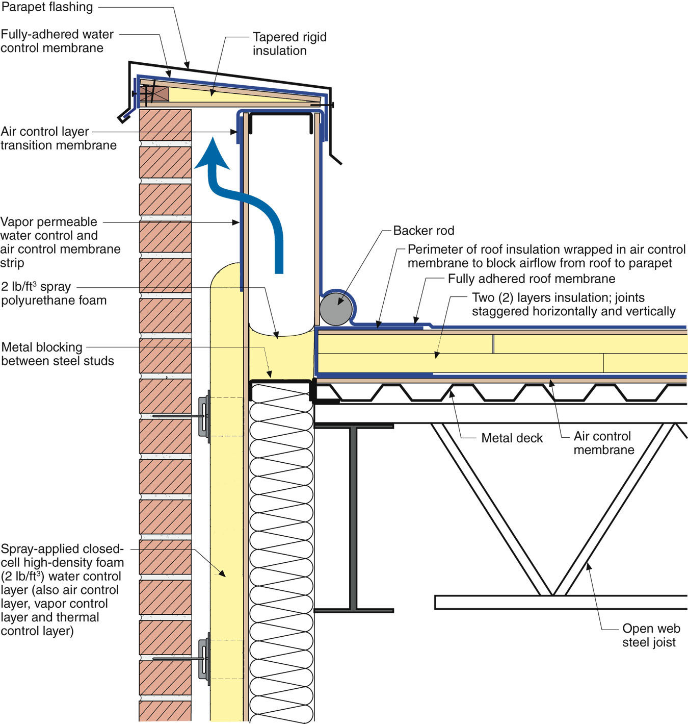
Figure 20: Parapet Control Layer Continuity – Balloon frame steel stud to steel roof.
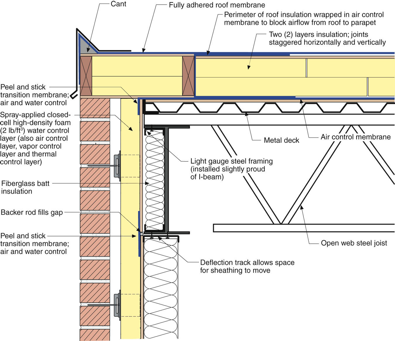
Figure 21: Parapet Control Layer Continuity – Zero height parapet.
FIRE RATED EXTERIOR WALL, INTERIOR SEPERATION WALL AND ROOF ASSEMBLIES
Figure 22 shows a 1 hour rated exterior wall assembly – UL – System No. EWS0015 insulated with up to 4 inches of high density closed cell spray foam. It can be constructed with a brick veneer, stone veneer, terracotta cladding and stucco.
Figure 23 shows a 2 hour separation wall insulated with low density open cell spray foam with a STC 50 rating using a single 2x4 wall – U301.
Figure 24 shows a 1 hour rated roof assembly insulated with up to 10 inches of low density open cell spray foam – P522.

Figure 22: Exterior Rated Wall – High density closed cell spray foam with a 1 hour rating – UL – System No. EWS0015. It can be constructed with a brick veneer, stone veneer, terracotta cladding and stucco.
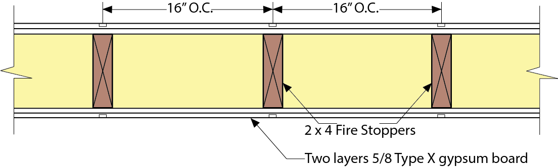
Figure 23: Separation Wall - 2 hour separation wall insulated with low density open cell spray foam with a STC 50 rating using a single 2x4 wall – U301.
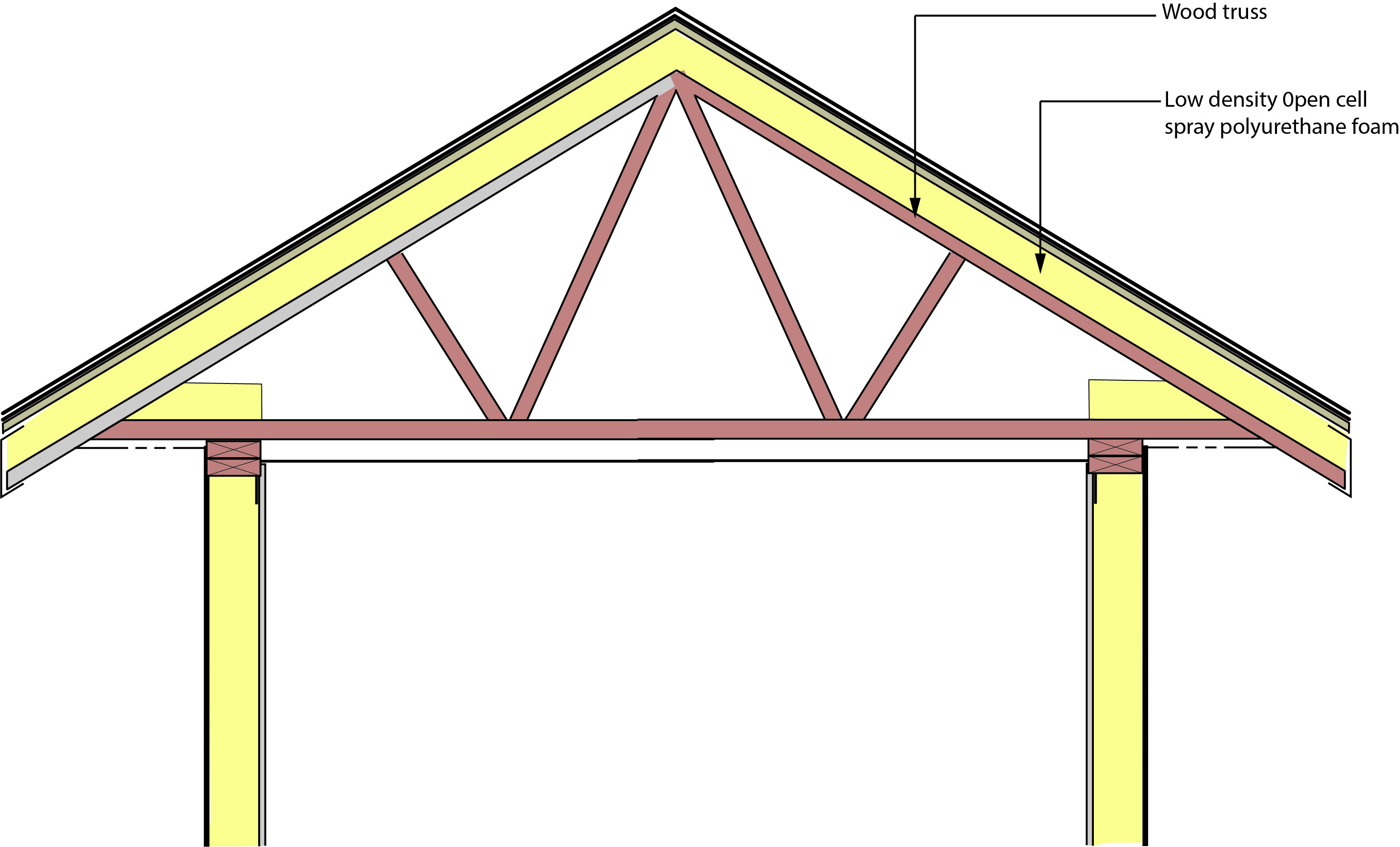
Figure 24: Conditioned Unvented Roof Assembly - 1 hour rated roof assembly insulated with low density open cell spray foam – UL P522.