I feel the earth move under my feet1
To state the obvious earthquakes are a major threat to the structural integrity of homes. New homes and existing homes need to be connected to foundations to withstand seismic activity. Structural engineers have got this pretty much figured out. The following discussion is not intended to address the structural engineering issues beyond a superficial manner. The intent is to add water management and thermal management to the structural engineering. The structural engineering has precedence – it has priority. I have said many, many times that when I make a mistake someone gets wet…boo-hoo…when a structural engineer makes a mistake someone can die2.
The water management and thermal management should be complimentary to the seismic design approach and seismic retrofit approach rather than be incompatible.
One of the keys to earthquake resistance is to control and transfer lateral loads (“shear”) caused by ground movement to foundations and the ground. This typically involves the following:
-
Providing wall to floor diaphragm anchors
-
Providing floor diaphragm to foundation anchors
-
Providing building bracing
The basis of water management and thermal management is to provide environmental separation:
-
Install a water control layer (rain and ground water)
-
Install an air control layer
-
Install a vapor control layer
-
Install a thermal control layer
Seismic Design Approach
The significant damage to buildings during earthquakes is caused by lateral movements. These lateral loads (“shear”) due to ground movement need to be transferred to the ground. We are going to focus on building to foundation connections.
Building to Foundation Connection
Figure 1 illustrates three foundation types typically found in high earthquake risk regions such as California: basement foundations, crawlspace foundations and crawlspace foundations with “cripple” walls. Note in all three foundations the connection of the continuous exterior structural wood sheathing (plywood or oriented strand board “OSB”) to the foundation sill plate is a big deal. Further note the connection of the foundation sill plate to all three concrete foundations is also a big deal. In this manner the wall to floor diaphragms are connected and in turn are connected to the foundation anchors.
Building bracing is typically provided by the use of continuous exterior structural wood sheathing (plywood or oriented strand board “OSB”). Note that the crawlspace foundation with a “cripple wall” has structural wood sheathing on both sides.
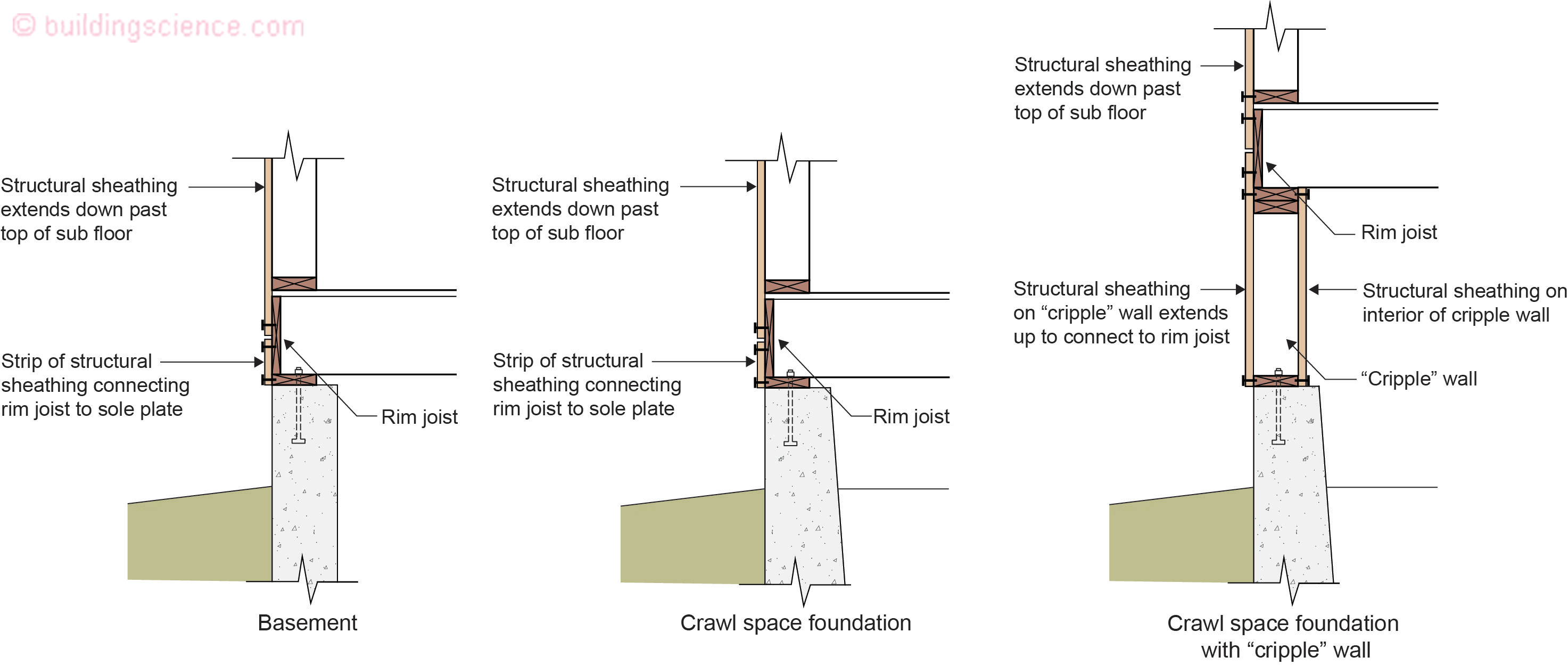
Figure 1: Basement foundation, crawlspace foundation and crawlspace foundation with a “cripple” wall. Note in all three foundations the connection of the continuous exterior structural wood sheathing (plywood or oriented strand board “OSB”) to the foundation sill plate. Further note the connection of the foundation sill plate to all three concrete foundations.
Additional bracing is provided in both crawlspace assemblies by installing cross bracing at interior posts and piers (Figure 2).
All three foundation types should also have solid blocking between floor joists. The solid wood blocking prevents the floor joists from “racking” or rolling sideways (Figure 2).
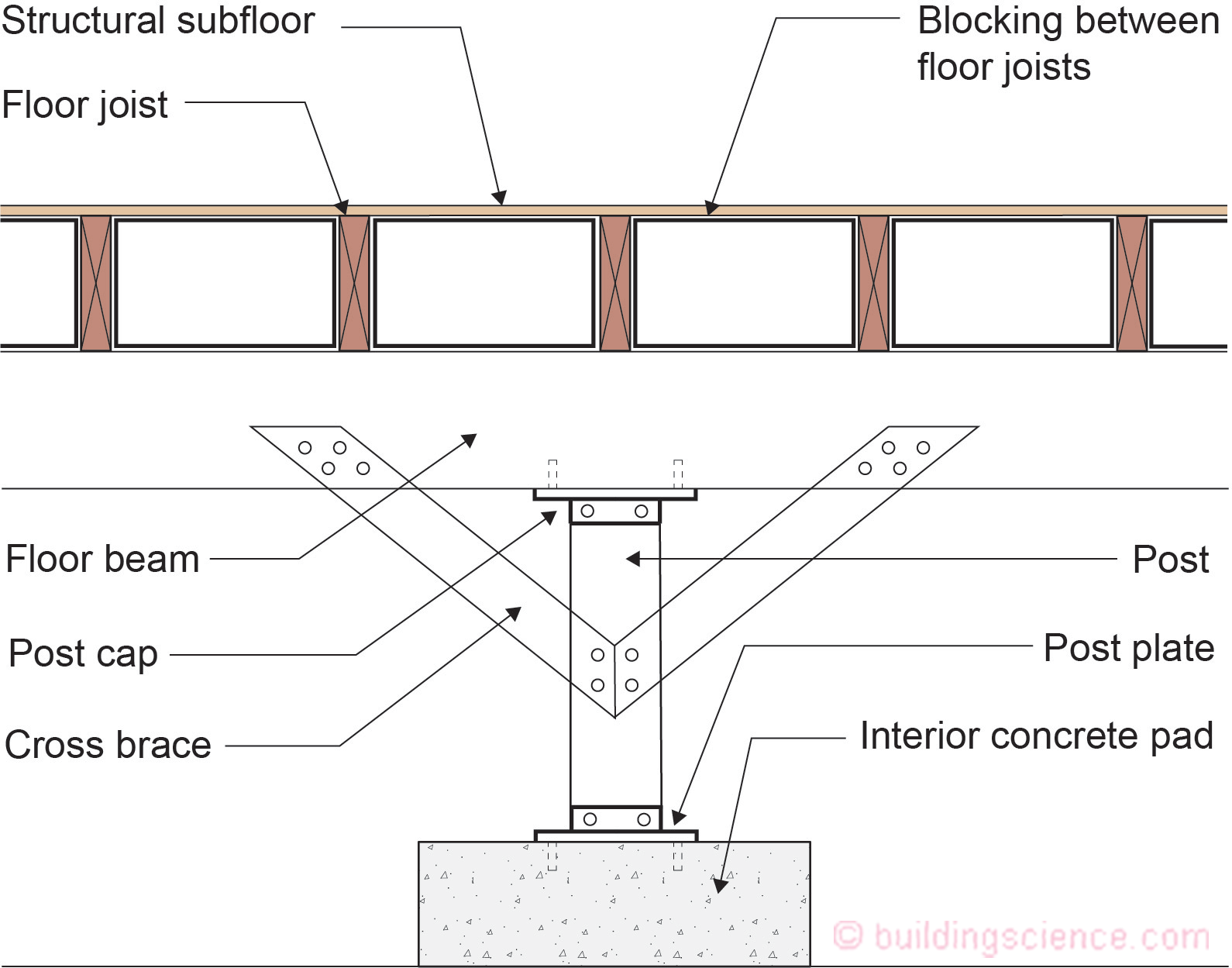
Figure 2: Interior posts and piers require additional bracing in both crawlspace assemblies by installing cross bracing. All three foundation types should also have solid blocking between floor joists. The solid wood blocking prevents the floor joists from “racking” or rolling sideways.
Basement Foundation
Figure 3 illustrates the environmental separation aspects of basement foundations.
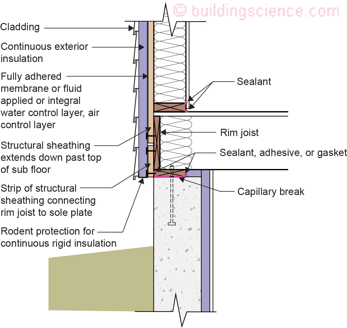
Figure 3: Basement foundation environmental separation.
A continuous water control layer controlling rain water is installed on the exterior of the wall structural sheathing and is connected to the continuous water control layer on the exterior of the basement foundation.
A continuous air control layer is installed on the exterior of the wall structural sheathing and is connected to the concrete foundation wall which is acting as the foundation air control layer.
Vapor control is provided by controlling the temperature of the wall assembly condensing surface by installing continuous exterior insulation. Vapor control of the concrete foundation is provided by installing dampproofing on the exterior of the foundation wall and a sheet polyethylene under the foundation slab.
Thermal control is provided by installing continuous exterior insulation and cavity insulation on and in the wall framing. Additionally, rigid insulation is installed on the interior of the foundation wall.
This approach works in all climates.
Crawlspace Foundation
Figure 4 illustrates the environmental separation aspects of crawlspace foundations. The crawlspace illustrated in Figure 4 is a vented crawlspace.
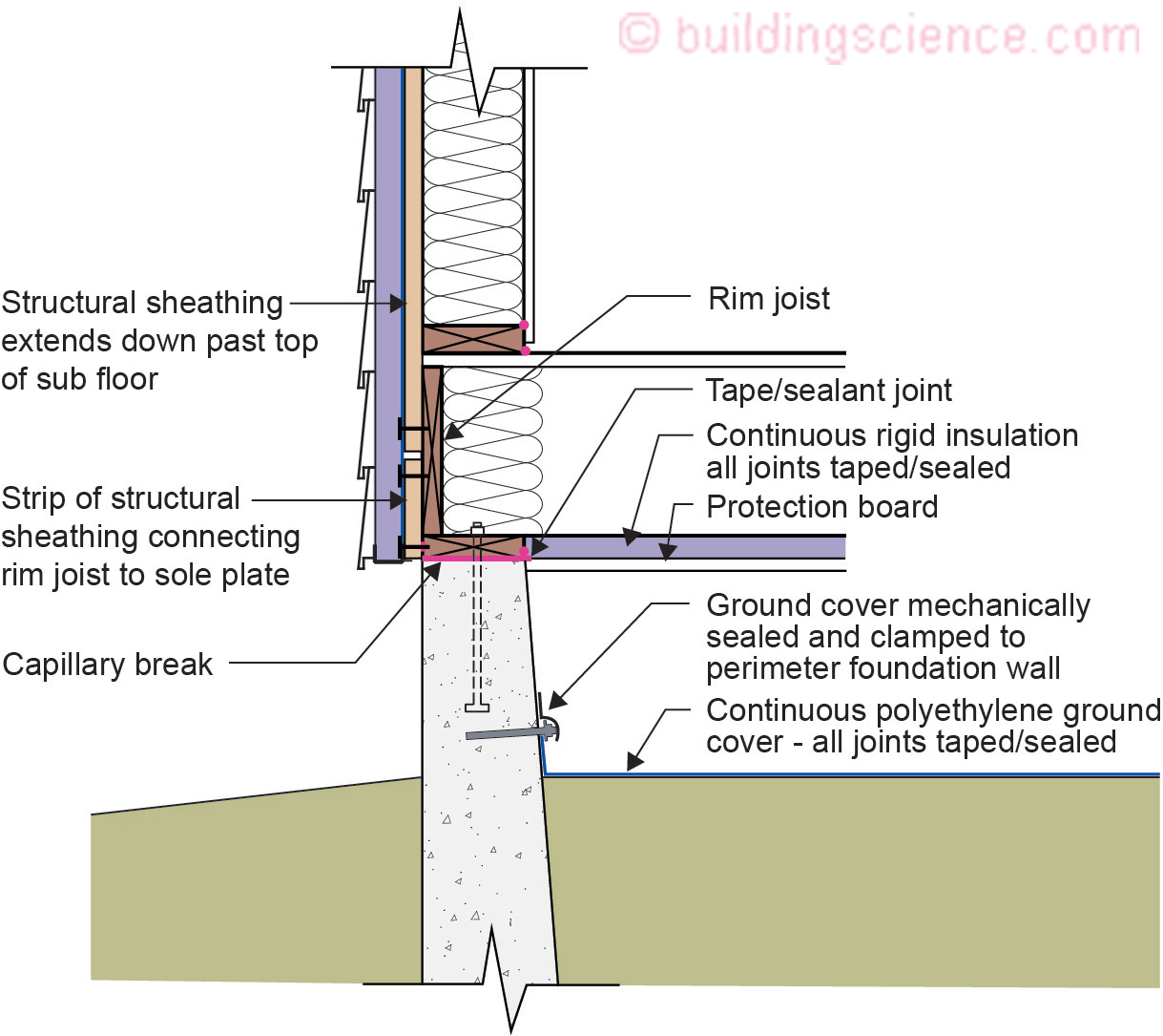
Figure 4: Crawlspace foundation environmental separation.
A continuous water control layer controlling rain water is installed on the exterior of the wall structural sheathing and is connected to the continuous water control layer on the exterior of the concrete foundation stem wall.
A continuous air control layer is installed on the exterior of the wall structural sheathing and is connected to the top of the concrete foundation stem and in turn to the continuous rigid insulation installed under the floor joists. The continuous rigid insulation under the floor joists is acting at the air control layer of the insulated floor assembly.
Vapor control is provided by controlling the temperature of the wall assembly condensing surface by installing continuous exterior insulation. Vapor control of the crawlspace foundation is provided by installing impermeable continuous rigid insulation under the floor joists. Additionally, a continuous polyethylene ground cover is provided.
Thermal control is provided by installing continuous exterior insulation and cavity insulation on and in the wall framing. Additionally, continuous rigid insulation under the floor joists.
This approach works in all climates.
Crawlspace Foundation With A “Cripple Wall”
Figure 5 illustrates the environmental separation aspects of crawlspaces with “cripple walls”. The crawlspace illustrated in Figure 5 is a vented crawlspace.
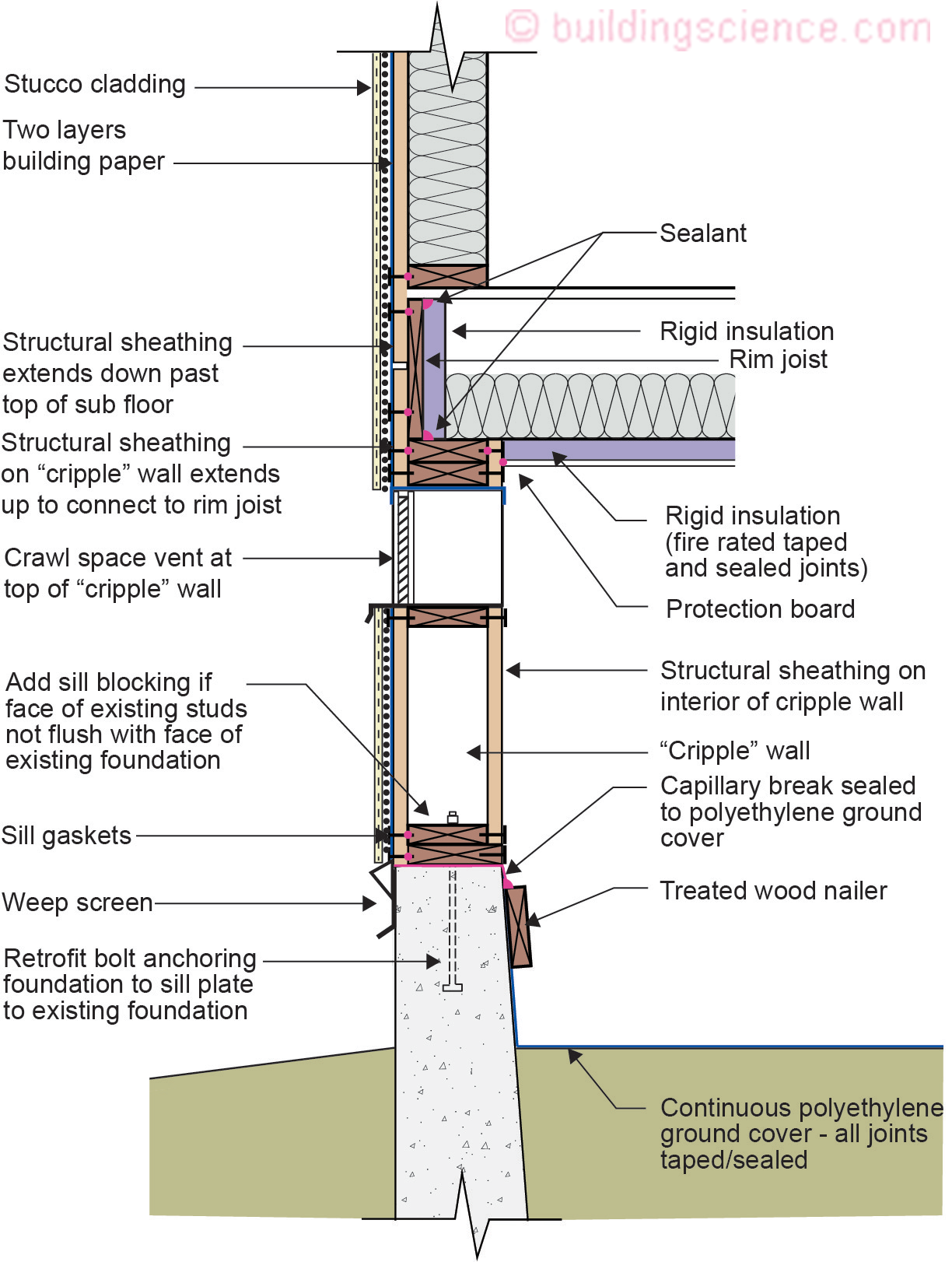
Figure 5: Crawlspace foundation with “cripple wall” environmental separation for a vented crawlspace.
A continuous water control layer controlling rain water is installed on the exterior of the wall structural sheathing and is connected to the continuous water control layer on the exterior of the concrete foundation stem wall. For stucco claddings it is recommended that two layers of building paper be used. The outer layer of the building paper acts as a “bond break” to facilitate drainage. The bottom of the stucco assembly should have a “weep screed” that acts as a flashing.
The air control layer of the exterior wall is typically the building paper. The air control layer of the underside of the floor framing is the continuous rigid insulation. This rigid insulation should be fire rated with joints taped and sealed. It is sealed to the interior of the perimeter “cripple” wall framing. The rigid insulation is also protected from animals, rodents and insects with a “protection board”.
Vapor control is provided by installing foil faced rigid insulation on the underside of the floor framing. Additional vapor control is provided by installing a continuous polyethylene ground cover that is connected to the interior of the concrete foundation stem wall and by providing crawlspace ventilation.
Crawlspace ventilation should have a minimum net area ventilation opening of 1 square foot for each 1,500 square feet of under floor area space when a Class I vapor retarder is used as a ground cover. The continuous polyethylene ground cover is a Class I vapor retarder. Additionally, the required crawlspace ventilation openings should be placed to provide cross ventilation of the space. It is recommended that at least four ventilation openings be located around the perimeter of the building. Ventilation openings should not be located under low decks or porches.
If a Class I vapor retarder ground cover is not installed the net ventilation opening area needs to be increased to a minimum of 1 square foot for each 150 square feet of under floor area. Note that the number of openings and vent area needs to be increased by an order of magnitude and this can adversely affect the ability of the “cripple” wall to resist seismic activity.
Thermal control is provided by installing continuous rigid insulation and cavity insulation on the underside of the floor framing.
This approach works in all climates.
Figure 6 illustrates the environmental separation aspects of crawlspace foundations also with “cripple walls”. The crawlspace illustrated in Figure 6 is an unvented conditioned crawlspace.

Figure 6: Crawlspace foundation with “cripple wall” environmental separation for an unvented conditioned crawlspace.
A continuous water control layer controlling rain water is installed on the exterior of the wall structural sheathing and is connected to the continuous water control layer on the exterior of the concrete foundation stem wall.
A continuous air control layer is installed on the exterior of the wall structural sheathing and is connected to the top of the concrete foundation stem and in turn to a continuous polyethylene ground cover that is extended up the interior of the concrete foundation stem wall. Figure 7 illustrates continuity of the air control layer at interior posts and piers.
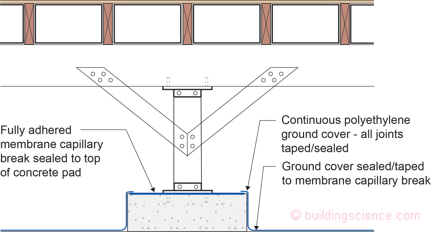
Figure 7: Continuity of the air control layer at interior posts and piers.
Vapor control is provided by controlling the temperature of the wall assembly condensing surface by installing continuous exterior insulation. Vapor control of the crawlspace foundation is provided by installing a continuous polyethylene ground cover that is extended up the interior of the concrete foundation stem wall.
Thermal control is provided by installing continuous exterior insulation and cavity insulation on and in the wall framing. Additionally, foil faced or plastic faced batt/roll insulation is installed on the interior of the concrete foundation stem wall extending horizontally over the polyethylene ground cover.
This approach works in all climates with the following limitation – in Climate Zones 5 and higher the foil faced or plastic faced batt/roll insulation must be replaced with impermeable rigid insulation or closed cell spray polyurethane foam.
Climate
The approaches to seismic control are climate independent – they work in all climates. However, the approaches to environmental separation are climate dependent.
Retrofit
The approach to seismic retrofit is the same as the approach to new design for seismic resistance. The basis of all earthquake resistance is to control and transfer lateral loads (“shear”) caused by ground movement to foundations and the ground. The same details discussed above for new foundation design also apply to retrofit.
Epilogue
Unlike the Carole King song…these foundations do not get “hot and cold, all over, all over”…“down to their very soul”…but I am pretty sure they are “mellow as the month of May”.
References:
Homeowner’s Guide to Earthquake Safety
Author(s): Collaborative for Disaster Mitigation, San Jose State University
Organization(s): California Seismic Safety Commission
Publication Date: 2020
https://ssc.ca.gov/wp-content/uploads/sites/9/2020/08/20-01_hog.pdf
FEMA 232 Homebuilders’ Guide to Earthquake-Resistant Design and Construction
Author(s): FEMA
Organization(s): FEMA
Publication Date: June, 2006
https://www.wbdg.org/ffc/dhs/criteria/fema-232
Footnotes:
1 The song does not have anything to do with earthquakes….The phrase originally comes from Ernest Hemingway and his 1940 work “For Whom the Bell Tolls” … I am pretty sure when structural engineers look at foundations done correctly they “feel their heart start to tremble”…
2 Consult a licensed engineer to develop the detailed approach for homes to withstand seismic activity. The seismic design can occur in conjunction with water management and thermal management where the approaches are complimentary rather than incompatible.