There are many existing buildings with load-bearing mass masonry walls, whose energy performance could be improved with the retrofit of insulation. However, adding insulation to the interior side of walls of such masonry buildings in cold (and wet) climates may cause performance and durability problems. Some concerns, such as condensation and freeze-thaw have known solutions. But wood members embedded in the masonry structure will be colder (and potentially wetter) after an interior insulation retrofit. Moisture content & relative humidity were monitored at joist ends in historic mass brick masonry walls retrofitted with interior insulation in a cold climate (Zone 5A); data were collected from 2012-2015. Eleven joist ends were monitored in all four orientations.
Executive Summary
Background Load-bearing mass masonry buildings comprise a significant fraction of the existing building stock in the United States. However, adding insulation to the interior side of walls of such buildings in cold climates may cause performance and durability problems in some cases. Some problems, such as interstitial condensation and brick freeze-thaw damage, are being addressed. Another durability risk that has received less investigation is the hygrothermal behavior of moisture-sensitive wood beams or joists that are embedded in the load-bearing masonry. Wood members that are embedded in a masonry structure are colder (and possibly wetter) after an interior insulation retrofit; the potential impact is not as well understood.
Literature Review
The U.S. Department of Energy's Building America research team Building Science Corporation (BSC) conducted a literature review of several practitioners who used in-situ monitoring and simulations to examine the moisture risks at embedded members in masonry walls. Monitoring of joist ends in Ontario, Canada (zone 6A), showed elevated moisture contents or MCs (20%+) but drier conditions in the low-rainfall climate of Saskatchewan (zone 7). European simulations showed that MCs in joist ends are highly dependent on wind-driven rain deposition rates. The practitioners also simulated the effect of leaving a gap in the insulation above and below the floor to allow greater drying. The European literature reviewed historical methods to protect beam ends. The European researchers covered field studies that typically found that driving rain did not cause moisture problems at beam ends. Some researchers found that cracks in the façade could cause problems, but crack-free façades had acceptable performance. BSC performed simulations of joist end geometries, including three-dimensional heat flow and one-dimensional hygrothermal simulations. These hygrothermal simulations gave inconclusive results; the author recommended in-situ measurements of beam pocket temperatures, relative humidities (RHs), and wood MCs.
Experimental Work
This work involved the field monitoring of embedded wood joist ends in a solid brick building in zone 5A that was retrofitted with interior insulation. Eleven joists throughout the building (which have a variety of orientations, exposures, and masonry wall types) were monitored for wood MCs at the embedded joist ends and for temperatures and RHs within the joist pocket. Indoor and outdoor conditions were also recorded. Results were collected for 28 months (December 2012–April 2015). One limitation was that the renovation was still ongoing; limited wintertime construction heating and no permanent occupancy were factors. Much of the building experienced cold interior temperatures (e.g., construction heating) during the winters. These were not typical interior heating set points. Because the building was essentially unoccupied, no significant interior moisture was generated. These boundary conditions are not normal service conditions.
Results and Conclusions
Overall, the RHs and MCs measured in joist pockets were higher than recommended for long- term durability. Many of the joist pockets had sustained conditions of 100% RH, and many wood MCs were in the 25%–35% range for extended periods. Typical guidance includes: (1) MCs lower than 20% are safe, and (2) decay fungi become active at MCs higher than 28%. ASHRAE 160 analysis showed that high RH levels coincided with temperatures that were high enough to support mold growth for most of the monitoring period (60%–70% of the hours) in most joists. However, no damage was seen at the joist ends when the instrumentation was installed or when a joist end sample was removed. This suggests that dense, old-growth framing might be able to survive these MCs without damage. Orientation has a significant effect on RH and MC levels: solar heating and drying kept all south- facing joist MCs well within the safe range. The east and west orientations had mixed results: some were in the safe range, but others exceeded the 20% MC level. The north side joists consistently had the highest MCs. Almost all the joists showed seasonal rises and falls; MC and RH conditions were higher during the summer and lower during the winter. This indicates the temperature gradient caused moisture to be driven inward during the summer. MC plots with driving rain showed no discernable correlations. In the parts of the building that had significant wintertime heating, many joists showed a drop in MC that coincided with the addition of heat, even after insulation and air sealing were installed. The joist ends showed a repeated pattern of MC measurements at their upper and lower ends. The lower joist end was consistently wetter than the upper joist end, which can be attributed to contact with the masonry pocket, gravity drainage of bulk water to the bottom of the pocket, greater drying at the top of the beam or deeper embedment at the bottom of the beam, and a larger air pocket at the top of the beam. The north-facing insulated and uninsulated joist ends were compared; a significant or consistent MC or RH difference was not seen between these cases. All three joist pockets essentially remained at a constant 100% RH. The retrofit neared completion in spring to summer 2015. This is the final Building America report for this project.
Guidance for Retrofits
Given the uncertainty demonstrated by the research, definitive guidance on the vulnerability of embedded wood members (i.e., a go/no-go situation) is difficult to formulate. Many of the joist ends operated consistently at high MCs, and the joist pockets demonstrated high RH (100%); these factors suggest the embedded members are at risk of moisture problems. However, disassembly revealed no structural decay. One risk factor is embedded beam ends that are near or below grade; they are vulnerable to splashback, capillary rise from the foundation, and exterior bulk water; details of methods that can ameliorate these issues are shown. Another method to protect beam ends is to apply exterior insulation in a horizontal band at that area if exterior aesthetic changes are permissible.
Another risk control method is to protect the joist ends with a preservative such as solid borate rods inserted into holes that are drilled into the joist end. These rods provide long-term protection from insect infestation and fungal decay; the preservative activates when the wood is wetted.
In high-risk situations (e.g., when water damage and wood decay are already evident), or when a very conservative approach is warranted, some options are presented for eliminating the embedded wood member condition entirely. Details are provided for cutting off the embedded “tail” of the joist to eliminate capillary wicking and supporting the floor structure from another point. Support options include joist hangers attached to the masonry, a continuous angle iron attached to the masonry, and a wood-frame-bearing wall below the joists.
1 Introduction
1.1 Background
Load-bearing mass masonry buildings comprise a significant fraction of the existing building stock in the East Coast and Midwest regions of the United States. However, adding insulation to the interior side of walls of such masonry buildings in cold (particularly cold and wet) climates may cause performance and durability problems. Some of these problems, which include interstitial condensation and brick freeze-thaw damage, have been (or are being) addressed (see Maurenbrecher et al. 1998; Gonçalves 2003; Straube and Schumacher 2002, 2004, 2007; Morelli et al. 2010; Straube et al. 2012; Ueno et al. 2013).
However, another durability risk that has been less investigated is the hygrothermal behavior of moisture-sensitive wood beams or joists that are embedded in the load-bearing masonry (Figure 1). With the retrofit of interior insulation, the embedded beam ends spend longer periods at colder temperatures than at their preretrofit condition. Therefore, reduced heat or energy flow reduces the drying potential of these wood members (Lstiburek 2008). The wood is also subjected to higher relative humidity (RH) conditions in the beam pocket and remains at a higher moisture content (MC); both factors increase the risk to the beam’s durability. Also, vapor- retarding insulation materials reduce inward drying.
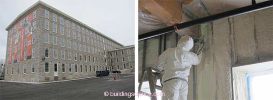
Figure 1: Mass masonry retrofit project overview (left); interior insulation at beam ends (right)
Solutions that have been proposed or used to protect embedded members include borate preservative injections into the wood, metal plates next to the member to provide passive heat flow, active heating at the beam ends, construction of a load-bearing structure inside the masonry, and cutting off the end of the beam.
Previous simulation work on embedded wood members in insulated masonry walls left many open questions, which could be addressed—at least in part—by in-situ measurement of embedded member MC. Therefore, the U.S. Department of Energy’s Building America research team Building Science Corporation (BSC) conducted field testing in collaboration with Merrimack Valley Habitat for Humanity in Lawrence, Massachusetts, which is currently renovating a mass masonry multifamily building into 10 condominium units with interior insulation.
The BSC team monitored 11 joists scattered throughout the building (which have a variety of orientations, exposures, and masonry wall types) for wood MC (low and high at the joist end) and temperature and RH within the joist pocket. Indoor and outdoor conditions were also recorded. Results were collected for 28 months (December 2012–April 2015). One limitation is that the renovation was still ongoing; limited wintertime construction heating and no permanent occupancy were factors.
As a general note, exterior insulation provides the ideal conditions for building durability for the masonry and embedded wood members. Exterior insulation addresses many thermal bridging problems (e.g., masonry tee walls) that occur with interior insulation. However, many buildings cannot be retrofitted with insulation on the exterior for reasons such as historic preservation, cost, zoning or space restrictions, and aesthetics.
1.2 Relevance to Building America’s Goals
Given the Building America goals of reducing home energy use by 30%–50% (compared to 2009 energy codes for new homes and preretrofit energy use for existing homes), insulation and air sealing of mass masonry walls will need to be components of the work if mass masonry residential buildings are to be addressed. Potentially millions of housing units could benefit from a better understanding of the moisture risks that are associated with interior retrofits and the means of reducing these risks.
Most construction that can benefit from this research is in locations with older building stock (i.e., mass masonry). The greatest concentrations are likely on the East Coast and in the Midwest (i.e., cold climates), although these types of buildings are definitely present throughout the country.
This research on the MC of embedded wood members addresses a durability risk associated with this insulation retrofit. If interior insulation retrofits are linked with significant numbers of moisture-related failures, the adoption of this retrofit measure will be set back.
The research covered here was judged relevant by the Building America Standing Technical Committee on Enclosures circa 2011 (when the monitoring project began); it was as a topic for additional research work (see Enclosures STC Strategic Plan: #32 Gap (Walls): Identify moisture damage risks associated with insulating embedded wood beams or joists in masonry walls; DOE 2011).
1.3 Cost-Effectiveness
Load-bearing masonry has a range of thermal properties; however, even a “thick” multiwythe load-bearing masonry wall is likely to have an R-value of R-3.2 to R-6.8; the average is about R-5. Surface heat transfer coefficients (“air films”) of another R-1 may result in thermal performance that is comparable to that of a high-end (i.e., triple-glazed) modern window; however, this level of insulation is too low for most practical purposes (considering current energy costs, building durability, and health and thermal comfort issues). Hence, insulation is often added during retrofits and is critical to achieving high performance (per Building America program goals) in any climate with significant heating loads.
The R-values of uninsulated masonry walls are also substantially lower than modern code requirements for cold climates; for zones 5 and 6, the typical opaque-wall “true” R-value requirements are R-12 to R-17 (as calculated from U-values given in the 2009 International Energy Conservation Code, Table 402.1.3; ICC 2009b).
Thermal insulation follows the law of diminishing returns; the return on investment decreases as insulation thickness increases. Given that these wall assemblies are being changed from uninsulated (base case) to insulated (final) assemblies, the initial 1–2 in. of insulation should be highly cost-effective. Optimization would be a function of insulation cost, energy costs, and climate zone.
BSC’s current retrofit recommendations include the use of air-impermeable closed-cell spray foam (ccSPF) as an interior insulation material for mass masonry walls. A typical installed price for ccSPF is roughly $1/board foot, although prices appear to be decreasing; when normalized by R-value instead of volume this cost is equivalent to approximately $0.16/ft2·R. In comparison, standard types of loose-fill fibrous insulation are sold at $0.02–0.04/ft2·R; this is a material cost, not an installed cost. If a 1:1 material-to-installation cost ratio is assumed for this estimate, ccSPF still costs about two to four times more than the lowest-cost loose-fill materials. However, as discussed by Straube and Schumacher (2007) and Morelli et al. (2010), the use of air- permeable and moisture-sensitive fibrous insulation in this application results in assemblies with a higher risk of moisture-related failures.
Interior insulation retrofit of mass masonry buildings is generally considered lower-cost (and therefore more cost-effective) than exterior insulation but has the attendant durability risks and performance limitations described earlier.
1.4 Tradeoffs and Other Benefits
Basic benefits of the retrofit insulation of uninsulated masonry walls include energy savings and thermal comfort improvements due to radiant surface temperature effects and air leakage reduction. The assemblies under discussion could, unlike the nonretrofitted assemblies, meet requirements for modern energy codes (Section 1.2).
As discussed in Section 1.1 and Section 1.2, the research on embedded wood members is being undertaken to ensure the retrofit of insulation in masonry structures does not cause substantial durability problems in the future.
2 Literature Review and Field Observations
Several practitioners have used in-situ monitoring and simulations to examine moisture risks at embedded members in masonry walls.
2.1 Dumont et al. (2005) Field Monitoring
Dumont et al. (2005) monitored the MCs of wood structural members that are embedded in masonry in two low-rise residences that were retrofitted with insulation in Wolseley, Saskatchewan (climate zone 7, "dry" climate), and Kincardine, Ontario (climate zone 6A, "moist" climate). The Wolseley house was insulated with mineral wool with a polyethylene vapor barrier; the Kincardine house was insulated with spray polyurethane foam. The foam insulation encased the wood members where they were seated in the masonry wall.
Data showed that the wood members of the Wolseley house remained at safe MC levels (10%–15%) throughout the monitoring period. This is not meant as an endorsement of the use of air-permeable insulation with an impermeable interior vapor barrier: this is actually a high-risk assembly. In reality, the lack of moisture load (dry climate/low rainfall) is likely the dominant factor. In contrast, the Kincardine house showed consistently elevated MCs (20%+) at several locations. The authors suspected the moisture source was capillary uptake from the wet foundation, but rainwater absorption through the face of the masonry (due to surface detailing) was not eliminated as a possible source. The limited drying to the interior available through spray polyurethane foam was also likely a contributing factor.
2.2 Scheffler (2009) Hygrothermal Simulations
Scheffler (2009) used simulations to examine the problem of moisture accumulation at wooden beam ends. He used DELPHIN two-dimensional hygrothermal simulation software, running a wooden beam embedded in brick masonry under steady-state conditions (23°F [–5°C]/80% RH exterior; 68°F [20°C]/50% RH interior; 90 days). These simulations demonstrated the moisture risks that are associated with insufficient control of airflow or moisture vapor flow (diffusion) from interior sources. This was followed by one- and two-dimensional simulations that used transient weather data (Bremen, Germany; mild, maritime climate with high rain and humidity) that indicated increases in RH and liquid water (condensation) at the beam ends caused by added insulation.
Scheffler also described the historical methods to increase embedded beam longevity, such as charring the beam end to increase moisture resistance and adding exterior-to-interior ventilation at the beam pocket. He discussed current methods to ameliorate these moisture issues, which could be caused by insulation retrofits, including replacing wood floor/ceiling assemblies with non-moisture-sensitive materials (e.g., concrete) and possibly adding heat or ventilation at the wood beam end.
2.3 Morelli et al. (2010) Hygrothermal Simulations
Morelli et al. (2010) collaborated with Scheffler to continue examining this issue. They proposed leaving a 12-in. (300-mm) gap in the insulation above and below the floor, which would result in a 30-in. (770-mm) gap (12-in. gap × 2 plus floor depth). Two- and three-dimensional heat transfer simulation showed the heat flow was reduced by 60% from the uninsulated to insulated cases; the gap case showed only a 45% reduction. This work was followed by two-dimensional DELPHIN hygrothermal simulations of the embedded beam (in a Bremen climate). RH levels in a corner of the beam pocket (and equilibrium wood MC) were compared between cases. The uninsulated wall showed a drying trend, the fully insulated wall showed seasonal RH increases, and the gapped insulation wall showed performance between the two previous cases but with increasing moisture levels. However, these results assumed a relatively high wind-driven rain- loading factor. Switching to a lower loading factor caused the gapped insulation assembly to show a general drying trend.
2.4 Morelli and Svendsen (2012) Simulations and Literature Review
Morelli and Svendsen (2012) continued the work of Morelli et al. (2010) by showing further simulations with continuous interior insulation versus insulation installed with a gap at the floor beams. This research also resulted in a methodology for assessing retrofit measures on brick masonry walls based on a failure mode and effect analysis.
Morelli and Svendsen also performed an extensive literature review from the 1980s to 2012. They examined several in-situ field studies and found that driving rain typically did not cause moisture problems at beam ends. Some researchers found that cracks in the façade could cause problems, but crack-free façades had acceptable performance. Another researcher examined the effect of interior air leakage at beam ends: at high air-leakage rates, temperatures in the beam pocket were higher and reduced condensation risks. At low air-leakage rates, air-transported moisture was negligible; however, at intermediate flows condensation did occur. That researcher recommended adding localized exterior wall insulation at beam ends or insulating the beam end cavity. Other researchers examined techniques such as adding heat to the beam ends to avoid moisture problems. The results kept wood MCs low, but it is an expensive (and therefore unlikely) retrofit.
2.5 Rudd (2014) Crawl Space Retrofit Field Measurements
Rudd (2014) described the retrofit of a crawl space in a circa 1940 multifamily building in the Philadelphia area (zone 4A). The crawl space foundations were ungrouted (hollow) concrete block with a brick veneer (Figure 2, left); above-grade walls were wood frame with a brick veneer. The first-floor framing (sawn lumber) was grouted in place and embedded in the concrete masonry unit wall (Figure 2, right).
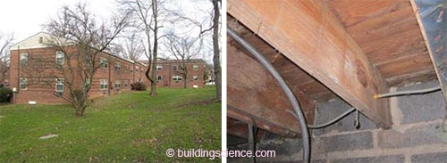
Figure 2: Overview of apartment complex (above left); preretrofit joist ends in concrete masonry unit walls (above right)
As an energy upgrade, the crawl space was converted from conventional vented/unconditioned to sealed and conditioned crawl space, per §R408.3 of the International Residential Code (ICC 2009a). Rigid foil-faced polyisocyanurate was installed on the crawl space walls and sealed around the joist ends (Figure 3). A continuously running exhaust fan was added to draw air from the crawl space; it pulls makeup air from the units above and provides a continuous supply of dry, semiconditioned air to the crawl space.

Figure 3: Postretrofit crawl space conditions (above left); insulation board sealed at joist ends (above right)
Joist MCs were measured: initially, they were 6%–10% in the main space and only 1–2 percentage points higher near the joist ends. However, the site later flooded (immersing the floor framing), and some joist ends remained at 40%+ MC. The author recommended cutting back insulation ½ in. around the joist ends to facilitate drying. Other joist ends had lower (10%–12%) MCs.
2.6 Ueno (2012) Heat Flow and Hygrothermal Simulations
Ueno (2012) examined this problem by first using three-dimensional heat flow simulations to determine the embedded beam and joist end temperatures with and without interior insulation (Figure 4). Various mitigation techniques, such as heat flow plates or omitting insulation, were also simulated.
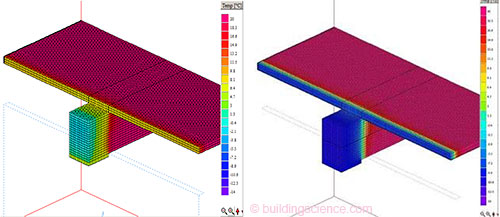
Figure 4: Embedded beam uninsulated case (left); insulated case (right) Source: Ueno (2012)
These results were then used to inform one-dimensional hygrothermal simulations of embedded beam ends. These simulations gave inconclusive results; the author recommended a possible first step of using of two-dimensional hygrothermal simulations.
However, greater and more defensible insights could be gleaned from in-situ measurements of beam pocket temperatures, RHs, and wood MCs in insulated and uninsulated configurations and various orientations and rainfall exposure levels. Based on Ueno’s conclusions, this current research project measured in-situ conditions of embedded wood joists in an interior insulated masonry structure.
2.7 Field Observations of Embedded Wood Members
The research team has examined many mass masonry buildings for potential interior insulation retrofits; this section covers some of the field observations from this work.
One common geometry, especially in mill or industrial buildings, is large timber beams (8–10 in. minimum thickness) at a wide spacing (Figure 5, left). The beams are fire cut (slant cut at the end to prevent wall collapse during a building fire; see Figure 30) and embedded in the masonry wall. Signs of water damage at the beam end (Figure 5, right) were relatively rare and were typically associated with roofing failures (on the top floor), water issues near grade, and poorly detailed roof-wall connections (which deposit excess water on the wall).
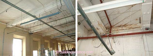
Figure 5: Typical large beam geometry (above left); water damage at beam end (above right)
These types of beams are typically pocketed with a steel or cast-iron plate to support it at the masonry wall (Figure 6). This plate was presumably installed for structural reasons (to distribute the beam’s load on the supporting masonry and form a flat surface), but it also functions as an effective capillary break to eliminate water wicking from the masonry below.
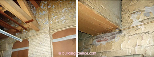
Figure 6: Large timber beam pocket (above left); iron or steel bearing plate (above right)
The sides of the beam sometimes have an air gap between the wood beam and the masonry; Figure 7 shows a relatively large (~¾-in.) gap. However, these conditions vary widely from building to building; some buildings have masonry tight against the beam.
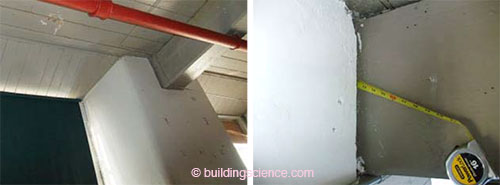
Figure 7: Beam pocket gap on sides; conditions vary by building

Figure 8: Steel saddle hanger detail, with beam clear of masonry wall at grade
One historic design in a Boston-area building clearly acknowledges the risks that are associated with wood beams near grade. Beam pockets were used for most of the building; however, at the basement level (with beam ends near grade), cast-in steel plate saddle hangers were used to support the beam (Figure 8). This detail completely removes the vulnerable wood from contact with the masonry (Figure 9, left). Several areas were stained (Figure 8, right) with paint blow- off; however, measurement of the wood MC showed dry conditions, even at extensively water- stained areas (Figure 9, right). Keeping the wood beam end clear of the wall (with this saddle detail) allows significant drying of any incidental wetting in service.
This wetting might have been caused by interior-sourced flooding, based on the water stain patterns (e.g., visible staining between subfloor gaps). Whatever the wetting source, however, this detail allows for greater drying than an embedded beam.
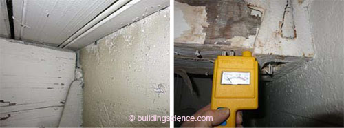
Figure 9: Wood clear of masonry (above left); low MC despite wetting stains (above right)
Individual joists that are composed of dimension lumber (2–3 in. width) at a close spacing (12–16 in. on center) constitute the other common geometry that is seen in residences and small commercial buildings . . .
Download the complete report here.