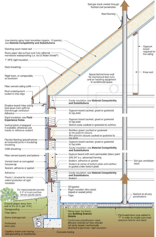
This two-story enclosure with a crawlspace is designed for Aspen, CO (Very Cold Climate). It features an unvented roof with low-density spray foam insulation in rafter cavities and 1” XPS rigid insulation at the underside of the rafters, and standing seam metal roof. The 2x6 advanced wood frame walls are insulated with cavity insulation and rigid insulation on the exterior of the wall sheathing, and feature fiber cement siding. The rim joist is insulated with cavity insulation on the interior. The crawlspace wall is insulated with rigid insulation on the interior with the floor of the crawlspace left uninsulated.
Enclosure Design
Construction Recommendations
- Foundation: Conditioned crawlspace
- Above Grade Walls: Wood frame
- Cladding: Fiber cement battened panels
- Attic: Cathedral living space
- Roof: Standing seam metal
Building Science Notes
Ducts in conditioned space – This building profile is designed to accommodate HVAC equipment and ducts in the crawlspace and second-story eaves behind knee walls. HVAC ducts should not be run in exterior walls.
Conditioned crawlspace – Conditioning of the crawlspace means that this space must be constructed much like a living space — it must be supplied by the HVAC system and have a transfer grille to return air back to the HVAC system located in the living space. The supply air should be directed horizontally across the crawlspace with good enough “throw” to provide some mixing, not directed down at the floor. Sizing of the supply air should be about 5% of the conditioned crawlspace floor area (For example: 0.05 cfm/ft2*1600ft2=80 cfm for a 1,600 ft2 conditioned crawlspace). A single 6-inch diameter supply duct typically suffices. Transfer air should go back to the central area of the living space above the crawlspace. Two grilles (10 inches by 4 inches) on opposite sides of the crawlspace will usually be sufficient. The transfer area should be calculated in the same manner as for closed bedrooms connecting to hallways, using the 3 Pa pressure difference limit. Some form of mechanical moisture control for the crawlspace is necessary. We recommend one of the following approaches:
In this assembly the rigid insulation is applied to the interior face of the exterior foundation walls. The R-value of the rigid insulation should follow the requirements for basement insulation in the most recent International Energy Conservation Code (IECC). Moisture control is important to proper performance; in particular, the vapor barrier ground cover on the floor of the crawlspace must be continuous and sealed to the perimeter wall and any supporting piers.
- A controlled ventilation strategy using the intermittent central fan-integrated supply — it provides both mixing and moisture removal for the crawlspace as well as the house.
- A stand-alone dehumidifier installed in the crawlspace.
- A continuously-operating crawlspace exhaust fan with make-up air extracted from the house.
- Air sealing details at transitions– Air sealing can be particularly difficult, but no less important, at assembly transitions such as band joists, and between attached garages and living spaces. These are discussed below because they have proven to be a consistent challenge for builders.
- Band joists – Continuity of an exterior air barrier can be maintained at the band joist with sealed or taped housewrap or rigid foam insulation. Continuity of an interior air barrier can be maintained through a combination of cut foam blocks and sealant/caulk, rigid draftstopping material (wood blocking) and sealant/caulk, or spray foam. Note that neither cellulose nor fiberglass (batt or blown) can be used for the air barrier. The air barrier detail on second-story band joists is important because it is inaccessible (covered by structural/finish floor and ceiling finish) after construction. Note that while fiberglass batts fulfill the requirement for protection from ignition in the open band joists, fiberglass batt material by itself cannot maintain the air barrier.
- Attached garages – the building enclosure surfaces shared between conditioned space and an unconditioned garage must have a continuous air barrier. See Figure 1 for details in terms of using sealants and rigid insulation to create a continuous air barrier between the attached garage and living space. See Air Sealing / Air Drywall Approach Details.
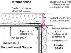
Figure 1
Drying mechanisms – In any climate, vapor control is based on the relationships among the following: the permeability of building assembly components, the type of cladding (reservoir or non-reservoir), the presence/lack/nature of an air space, and the magnitude/duration of the vapor drive (based on the relationship between the exterior and interior moisture content and temperature differences). The type of sheathing and housewrap used in any wall assembly must be based on an understanding of these inter-relationships. See “Insulations, Sheathings, and Vapor Diffusion Retarders” for more information.
In cold and very cold climates, the moisture load is dominated and driven by the interior, so roof and wall assemblies are generally designed to dry primarily to the exterior (particularly since climates this cold are likely to have little to no active air conditioning in the summer months). Wintertime condensation control can be facilitated by elevating the temperature of the first condensing surface.Given the very limited drying potential of this roof assembly, particular care must be taken to prevent the entry of bulk water (i.e. leaks) and to control interior relative humidity in the coldest months. See Material Compatibility and Substitutions.
- Wall assembly: The first condensing surface is the inside of the exterior sheathing because the insulating sheathing warms the entire framing cavity. The thickness of the insulating sheathing is determined by calculation based on the severity of the climate (see “Insulations, Sheathings, and Vapor Diffusion Retarders”). Walls constructed with XPS insulating sheathing are designed to dry to the interior during the summer months. Latex paint or some other vapor retarder (i.e. the kraft facing on fiberglass batts or CertainTeed’s MemBrain™ Smart Vapor Retarder) acts to slow moisture entry in to the framed assembly from the interior during the winter yet permits drying during the summer. Ideally, the more vapor permeable EPS rigid insulation works well as the thickness of insulation goes beyond 1 inch, but see Field Experience Notes for more discussion.
- Roof assembly: This assembly has only limited drying potential to the interior. The ice and water shield on the exterior virtually eliminates drying to the exterior; the XPS rigid insulation on the interior is marginally semi-permeable. However, the air tightness of this assembly—air-impermeable spray foam cavity insulation and continuous interior rigid insulation—eliminates the single largest potential for moisture problems—air-transported moisture. Also, the first condensing surface is the interior face of the rigid insulation, protecting all the framing and roof sheathing from the lion’s share of the moisture drive from the interior. Additionally, the interior rigid insulation creates a thermal break for rafter framing, framing that in this case spans from the inside to the outside of the assembly. See Material Compatibility and Substitutions as well as the “Boston” building profile for more information.
Drainage plane, air barrier, vapor control
- Walls - This wall assembly is a ventilated system—the air space formed by the vented mesh (such as Benjamin Obdyke Home Slicker) or corrugated housewrap (such as StuccoWrap) is open at the top and bottom of the assembly to promote air flow. The drainage plane is the flashed rigid insulation. Note how a “z” strip of polyethylene flashing maintains the continuity of the drainage plane at horizontal joints in the rigid insulation and mastic or adhesive sealant maintains drainage plane continuity at vertical joints. This building profile has a continuous air barrier on the interior (Airtight Drywall Approach on ceiling and walls). Note that the vapor permeability of the rigid insulation in the crawlspace wall assembly must allow some drying potential of the assembly to the interior.
- Roof - Because this roof assembly has very little drying potential and capacity to benignly store water, the continuity and robustness of the roof drainage plane is critical to roof assembly performance. Flashing at penetrations must be exemplary. See the drying mechanism discussion above regarding the air barrier and vapor control for this roof assembly.
Rough opening flashing – Flashing must be installed at the plane of the XPS rigid insulation for drainage plane continuity. See Figure 2. For more details see theWater Management Guide.
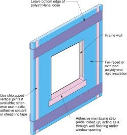
Figure 2
Advanced framing – This wall assembly replaces structural sheathing with cross bracing or some alternative for shear resistance; thermal performance and reduced drywall cracking are additional benefits of a comprehensive approach. See Advanced Framing for details.
Framing on slabs – Installing a capillary break between the sill plate and a concrete slab on all walls—exterior, interior, partition—is good practice. A closed cell foam sill sealer or gasket works well. Alternatively, a strip of sheet polyethylene can be used. This isolates the framing from any source of moisture that may be either in or on the concrete slab (and using sill sealer on all walls maintains the same wall height).
Soil gas ventilation – The sub-slab to roof vent system handles conditions that are difficult if not impossible to assess prior to completion of the structure—resultant confined concentrations of air-borne radon, soil treatments (termiticides, pesticides) methane, etc. The cost of this “ounce” of prevention is well balanced against the cost of the “pound” of cure.
Sub-slab stone bed - The four-inch deep, 3/4-inch stone bed functions as a granular capillary break, a drainage pad, and a sub-slab air pressure field extender for the soil gas ventilation system. Without it, a soil gas ventilation system is not practically possible and the only capillary break between the slab and ground is the polyethylene vapor barrier or the rigid insulation under the slab.
Climate Specific Details
Below-grade insulation – Ground temperatures make foundation wall and slab insulation an important part of the thermal barrier.
Above-grade insulation – Homes in this climate benefit from exterior insulation that warms whatever structural material is to its interior, protecting it from the moisture degradation that can occur as the result of condensation.
Ice dam protection – The combination of adequate insulation just above the exterior wall, and air sealing at the wall-roof assemblies transition are essential to prevent ice dams. But ice dams can occur even in properly detailed roof assemblies from differential solar snow melt. A water protection membrane over the entire roof surface is recommended on all roof assemblies in this climate.
Mechanicals
- Cooling – High performance homes in this climate do not require central forced air cooling. High performance ceiling fans, shading, and strategically located operable high performance windows can provide adequate summertime comfort.
- Ventilation and Space Heating -
For homes with central forced air distribution system:For homes without central forced air distribution system:
- A sealed combustion hot air furnace. A single central return requires transfer grilles to provide return path and avoid pressurizing bedrooms (see Figures 3a-d).
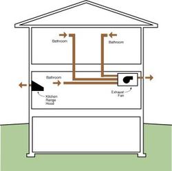
- Continuous multi-point exhaust, designed to ASHRAE 62.2P rate, pulling from each bedroom, unless the bedroom has a bathroom then it will pull from the bathroom, and pulling from at least one location in the principal living area. A fan-cycling control for the central air handler provides mixing only. Any combustion appliances must be powerdirect vented sealed combustion.
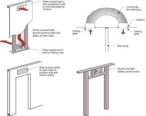 Figure 3a-d |
Sealed combustion boiler serving both space heating and domestic hot water heating.
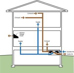
Ventilation can be accomplished using a continuous exhaust system (see Figure 4) or an HRV or ERV. HRV or ERV systems should not be hard-connected to the HVAC system and should involve some provision for periodic whole-house mixing (see Figure 5).
Humidification - In Very Cold climates, where some form of winter-time humidification may be demanded by the occupants, a humidistat must be installed so that occupants can monitor and keep the relative humidity no higher than occupant comfort demands. For more information see Relative Humidity.
UV exposure – High altitude environments have significantly higher UV exposures than lower altitude environments. This should be taken into consideration in the selection of roof and wall claddings, as well as windows (in terms of glazing properties). Masonry building materials (roof tiles, brick, stucco) are naturally more UV-resistant. Many metal wall and roof claddings are more UV-resistant—depending on the nature and quality of finish—ask your product supplier for standardized test information on the UV performance of all materials used on the exterior of the building.
Field Experience Notes
Selection of rigid insulation – Most builders select rigid insulation based on costs and handling properties, not material properties such as vapor permeability. This and other Building Profiles show XPS in most wall assemblies because it is generally preferred by builders as “tougher” than EPS. This is often because the right type of EPS is not being carried for building applications—see the Building Materials Property Table (coming soon) for more information on both EPS and XPS. But remember, the type of sheathing to use is always a question that should be asked in the context of the given cladding, the level of control that can be expected over interior relative humidity via mechanical ventilation, and the amount and direction of drying potential the wall assembly requires. See “Insulations, Sheathings, and Vapor Diffusion Retarders” and Material Compatibility and Substitutions for more information.
Joint treatment in rigid insulation – The type of rigid foam insulation best suited for multifunctional application including the drainage plane, shiplapped rigid foam insulation has proven to be available in only very limited areas. Mastic works as a water sealant; its long term performance is not known but appears promising. The flexible flashing with polyethylene film is straightforward and creates a natural weatherlap and therefore is the preferred approach.
Flashing details – Both the rough opening and the window should be flashed—either one can leak. Note that installation of windows before or after the drainage plane (in this case the rigid insulation) affects the flashing sequence, how much of the flanged window extends outside the plane of drainage, and window trim details.
Advanced framing – For a technical resource that may help with resistance to advanced framing methods from local code officials, see the Building Safety Journal article written by Peter Yost of BSC.
Stepped foundation insulation detail – Maintaining thermal barrier continuity in stepped foundations has proven difficult or easy to neglect. Figure 6 shows how the rigid foam needs to be cut and placed.
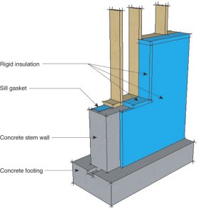
Figure 6
Eave insulation – the spray foam insulation stop between rafters in the roof assembly can be either blocking (see Figure 7) or rigid insulation from the wall cut out to extend up and between each rafter.
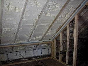
Figure 7
Unvented roof assembly – There are other approaches to unvented roof assemblies in very cold climates—the one portrayed in this assembly is among the more cost-effective. See Material Compatibility and Substitutions for more information.
Material Compatibility and Substitutions
Cavity insulation in the unvented roof assembly – There are essentially four ways to manage heat, air, and moisture flow in an unvented roof assembly in very cold climates:
NOTE: only the fourth option can involve cavity fill insulation other than spray foam—spray foam is the only uniform, air-impermeable cavity fill insulation appropriate for the first three options.- Fill the entire framing cavity with low-density spray foam insulation and install 1-inch rigid foam insulation to the interior of the framing. In this case, the spray foam insulation effectively moves the first condensing surface to the inside of the assembly, and the rigid insulation both protects thermal bridging and condensation potential at the rafters and lowers the permeability of the interior of the system (open cell spray foam being about 10 perms and 1-inch of XPS rigid foam insulation being about 1 perm). This system is best suited for rafter framing and is the system shown in this building profile.
- Install spray foam insulation to the depth desired or required for R-value and, after the foam has cured, cover the inside surface of the spray foam with either latex paint or (if code considerations require a system of protection against combustion) install gypsum board painted with latex paint. This system moves the first condensing surface to the inside face of the cavity insulation and is best suited for roof truss framing because the spray foam depth encapsulates all roof framing (except portions of the webs). See the “Boston” building profile.
- Install high-density spray foam as the cavity insulation. Its vapor permeability is low enough that no latex paint coating is required, although gypsum wallboard or fiberglass insulation with foil facing may be required for code compliance (See the "Boston" building profile).
- Install enough rigid insulation to the exterior of the structural system (roof sheathing and framing) to warm the structural system and prevent condensation (the first condensing surface is the exterior surface of the structural roof sheathing). The general rule of thumb is 1-4-inch of rigid foam per 1,000 heating degree days (but this rule involves the interior conditions as well—interior relative humidity during the coldest months affects the level of exterior rigid insulation required to manage condensation). In very cold climates, this involves deep enough rigid insulation to require another layer of sheathing on the exterior of the insulation to act as the nailing base for the roof cladding. This system works for any type of roof framing system but is not very common because of relative first cost
Rigid Insulation – There is a significant difference in the vapor permeability rigid insulations (see the Building Materials Property Table). Along with thermal considerations, consider the rigid insulation that best suits the wall assembly’s need for managing the flow of moisture into (wetting) and out of (drying) the entire wall assembly.
Rim joist material – The dimensional stability (less shrinkage) of engineered wood versus solid sawn make this a better choice for this deep framing member. An alternative that also deals with the thermal difficulties of this area of the assembly is a Structural Insulated Panel (SIP) band joist.
Rim joist blocking – An alternative to this detail is to spray foam insulation on the rim joist to maintain air barrier continuity at this transition.
Drainage plane on rigid insulation – An alternative to flashing, shiplapping, or sealing the XPS insulation for continuity of the drainage plane is to apply a housewrap to the outside of the insulation; a corrugated one such as StuccoWrap® also provides an air space (see the "Boston" building profile). The housewrap then becomes the continuous drainage plane.
Interior latex paint - The substitution of low permeability interior finishes (vinyl wall paper, oil-based paints) for latex paint is not recommended.
Cavity insulation materials – Acceptable cavity insulation includes any that have a relatively high vapor permeability—cellulose, fiberglass, foam (as long as air sealing is accomplished by a separate component or system when cellulose or fiberglass is used). User discretion can be based on properties other than building science.
Gypsum wallboard –Areas of potentially high moisture, such as bathrooms, basements, kitchens, are excellent candidates for non-paper faced wallboard systems (e.g. James Hardie’s Hardibacker®, GP’s DensArmor®, USG’s Fiberock®). In addition, paper-faced gypsum board should never be used as interior sheathing or backer for tub or shower surrounds where ceramic tile or marble (any material with joints or grout lines) is used as the finish.
Cast concrete foundation walls – If block is used instead of cast concrete for foundation walls, the bond beam becomes essential to maintain air barrier continuity at the top of the block wall.
L-channel detail on cladding at base of exterior wall – Any stop can be used at the bottom, exposed edge of the rigid insulation to prevent insect and rodent intrusion, as long as it does not interfere with the foam’s function as the drainage plane.