Water causes enough trouble by itself, but when we add salt we go to a whole different level, especially where porous materials are concerned. What is the deal with porous materials? Simple, porous materials are capable of wicking water large distances due to capillary suction (1). And when water can move large distances only bad things can happen.
Some of the tiniest pores can be found in wood, concrete, mortar and brick. Guess what we like to build out of? Yup, wood, concrete, mortar and brick. The theoretical limit of capillary rise in concrete is about 10 kilometers—and folks that is not a typo—it really is about 10 kilometers or about 6 miles. Concrete sucks big time. In wood it is about 400 feet—the height limit trees can grow to is set by the size of the capillary pores in wood. Ever wonder how leaves get water? When you go into a forest and listen very carefully you don’t hear any pumps pumping water upwards a couple of hundred feet do you? Capillary suction is powerful stuff. When you add salt to the water the power becomes explosive—literally as we shall see.
It is pretty common for ground water to dissolve mineral salts found in the earth. These dissolved mineral salts are transported by capillarity in solution through porous soils. When porous building materials are in direct contact with porous soils the building materials also wick the water inwards and upwards. Concrete footings are typically placed directly onto soil without any intervening capillary break and water wicks upward into the structure. The Brits call this “rising damp.” This rising damp or capillary ground water can cause serious damage in buildings. In new structures the problem is easy to avoid by installing a capillary break on the top of footings. We already provide capillary breaks under slabs—stones or sheet membranes such a polyethylene—and on the exterior of foundation walls by coating them with bitumen (“dampproofing"). Adding capillary breaks over the top of footings makes the protection continuous and avoids moisture problems when below grade interior spaces are insulated and finished (Figure 1). But how do we deal with existing structures—especially the old ones? We had better figure this out as we have a lot of old buildings to retrofit if we are going to be serious about climate change and energy security.
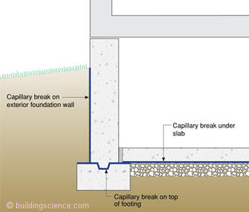
Figure 1: Capillary break over footing—Not a common practice, but it should be due to the likelihood of finishing and insulating interior below grade spaces.
The best way to understand old buildings is to talk to old people. Unfortunately the old people we need to talk to are so old they have been dead for a long time. Hence, we have to use a new tool unknown in the Internet age—books—and really old ones that are typically written in some language other than English by some long dead European.
First a little “engineering physics”1 to help us get our arms around salt and water in porous materials. Figure 2 shows water with salt in solution traveling through a porous material by capillary flow to a surface where evaporation occurs. As the capillary water evaporates from the surface the salt is left behind. As water continues to evaporate from the surface this leads to an ever-increasing concentration of salt in the material. This increasing concentration of salt disturbs matters and to re-establish equilibrium water rushes towards the salt to dilute the concentration of salt. This can lead to huge hydrostatic pressures within the porous material. Aficionados (a.k.a. “geeks”) will recognize this as “osmosis.”
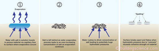
Figure 2: Spalling of porous materials—Without salt present evaporation of water from porous surfaces can often be easily managed—with salt present significant damage can occur.
The forces are not trivial (see below)(2). The osmosis pressures can exceed the cohesive strength of most porous materials and they literally blow apart.
Diffusion Vapor Pressure: 0.3 to 0.5 psi (2.1 to 3.5 kPa)
Capillary Pressure: 300 to 500 psi (2.1 to 3.5 MPa)
Osmotic Pressure: 3,000 to 5,000 psi (21 to 35 MPa)
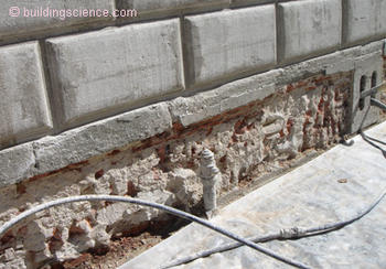
Photograph 1 shows salt on the above-grade exposed surface of a brick foundation. Water carries salt in solution to the surface of the brick where the water evaporates leaving behind the salt on the surface of the brick in the form of salt crystals. The white deposits of mineral salts are called “efflorescence.” When the crystallization of salts happen beneath the surface of the brick-mortar matrix the phenomenon is called “sub surface efflorescence” or “sub-florescence.” If the subflorescence leads to sufficiently strong osmotic pressures—greater than the strength of the brick—and the brick flakes apart the damage is called “spalling.”
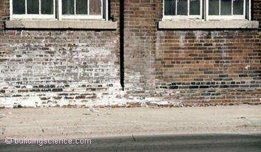
Photograph 1: Efflorescence on brick foundation
Figure 3 illustrates the all too common situation at the base of a brick foundation in an old building. The mortar fails near the base of the wall due to sub-efflorescence. The damage is localized near the base of the wall as the capillary water does not travel upward very far as it is easier for it to evaporate inwards rather than travel upwards. If it is prevented from evaporating inwards, the capillary water will travel upwards—again as we shall see.
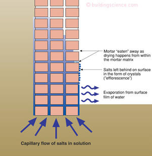
Figure 3: Efflorescence and spalling brick in foundations—Damage is limited to lower portions of foundation, closest to the source of capillary water and salt.
One of the things you notice when you read old books written by old people is that they noticed things—seemingly little things that most of us would overlook but that actually turn out to be big things. Old master masons in the old world noticed that the mortar in the joints of brick assemblies would get “eaten” away at a much faster rate than the brick itself if the mortar had a lot of lime in it. The lime made the mortar weaker and more liquid water permeable and more vapor permeable than the brick—it made the mortar a “preferential” matrix for salt laden capillary water. They noticed that the capillary water with the dissolved salt preferred the mortar matrix to the brick.
This observation lead to the old practice, and good practice, of wanting mortar to be weaker and softer than brick—both above grade and below grade. Preservationists go through a lot of brain damage analyzing mortar chemistry to make sure this is the case when they replace old mortar using a process called “re-pointing.” You do not want the mortar to be stronger than the brick, because then the brick “sacrifices” itself to protect the mortar not the other way around. Note to structural engineers: stronger is not better where mortar is concerned—listen to the preservationists on this one.
Figure 4 illustrates the elegant solution to the problem of efflorescence, sub-efflorescence and spalling courtesy of a long dead old world mason. The re-pointing of brick with weak lime based mortar was seen to protect the brick from damage. The mortar would “sacrifice” itself to protect the brick. The re-pointing of the brick with “sacrificial” lime mortar over time evolved into applying “sacrificial” coatings over the entire brick surface. The lime-mortar rendering (or “parge coat”) would preferentially attract the capillary salt-water solution and evaporation would happen in this layer not in the brick-masonry assembly. The spalling and damage would be limited to the sacrificial layer. The lime-mortar layer would act like a “poultice” sucking the “salt poison” out of the assembly. The sacrificial layer would eventually fail and fall off—as expected—and would need to be replaced 3 or 4 times a century.
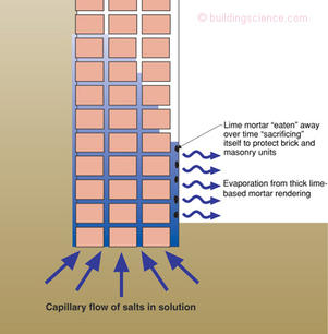
Figure 4: Sacrificial layers—Old world technology at its best. If you can’t stop the damage function, at least concentrate it at a location where you can deal with and within a material you can replace.
Photograph 2 shows a sacrificial layer failing on the exterior of a foundation wall at grade in the old town of Siena, Italy letting its owners know that it is time to reapply a new sacrificial layer. Photograph 3 shows a new sacrificial layer being applied on a building in the author’s ancestral home of Prague in the Czech Republic. Photograph 4 shows a recently applied sacrificial layer on one side of a doorway—but not yet applied on the other—on a building in Firenze, Italy.
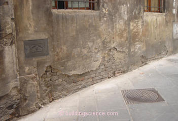
Photograph 2: Spalling of sacrificial layer in Siena, Italy
Photograph 3: Sacrificial layer being applied in Prague, Czech Republic
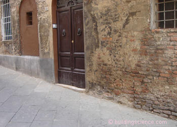
Figure 5 illustrates an approach to address osmosis problems when retrofitting existing brick foundations. A sacrificial layer of lime-based mortar is applied to the exterior of the foundation at grade. An interior liquid water impermeable and vapor impermeable layer is applied to the masonry foundation preventing the capillary water from evaporating to the interior. The capillary water is directed upwards and outwards to the exterior sacrificial layer. The salt accumulates in this layer rather than causing damage to the interior of the foundation. This allows the interior of the masonry foundation to be insulated full height from the slab to the underside of the floor assembly.
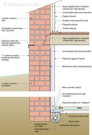
Figure 5: Retrofitting existing brick foundation—Damage function is concentrated on outside surface of foundation at grade in a material designed to be replaced 3 or 4 times a century. Interior membrane sheet waterproofing is designed to prevent inward drying of capillary water—water is directed upwards and outwards.
Here is where things get tricky—we want to direct the capillary water upward and outward—but not too far upward into the structure where it can damage timbers and interior finishes. Figure 6 provides guidance for the protection of embedded timbers in masonry foundations when directing capillary water upward and outward.
At the end of the day in order to deal with old buildings that need to be retrofitted to meet the challenges of climate change and energy security it appears that we will have to dust off some old world technology. It is not too big of a sacrifice to ask.
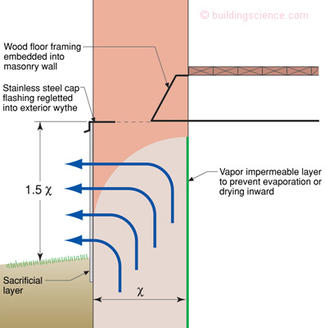
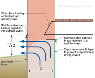
Figure 6: Rules of Thumb—Physicists hate this type of information—experienced based recommendations without formal equations derived from first principles. I will come clean here—this is a “best guess” on my part. But I have been around and have been pretty good at guessing at stuff like this.
Footnote:
Not true physics—but close enough—engineers deal with approximations and “fudge factors” (i.e. “coefficients”) so “engineering physics” are “approximately correct.” If we engineers waited for physicists to solve things nothing would ever get done. We’re still waiting for physicists to explain friction from first principles. Until they do we will use our “coefficient of friction” and the trains will run and the planes will fly.
References
Hutcheon, N.B. and Handegord, G.O.; Building Science for a Cold Climate, National Research Council of Canada, 1983.
J.F. Straube and Burnett, E.F.P.; Building Science for Building Enclosures, Building Science Press, Westford, MA, 2005