Water comes in four forms: solid, liquid, vapor and adsorbed. All four forms can cause grief to building owners, designers and contractors. When water causes building problems investigating and diagnosing the problem can be challenging because water constantly changes its form inside a building and within its materials. The investigator must hunt down the water thinking like water.
Introduction
Water is supposed to be easy to understand. It only comes in four forms or states [1]. And the rules governing water movement are straightforward:
- Water runs downhill due to gravity.
- Air carrying water vapor goes from areas of higher air pressure to areas of lower air pressure.
- Water in the vapor form diffuses from warm to cold driven by the thermal gradient.
- Water in the vapor form diffuses from more to less driven by the concentration gradient.
Ok, not always straightforward: - Water in a porous material diffuses on pore surfaces from more to less along the concentration gradient in the form of adsorbed water. When there is a lot of it and it fills the pores it is sometimes referred to as capillary water. In this way it can move upwards against the force of gravity – or sideways long distances. Just remember that porous materials “suck” and you’ll be ok.
Water always changes its behavior, because its form is never constant. Evaporation, condensation, capillary suction, gravitational flow, vapor diffusion and mass flow of moist air are all happening at the same time inside building cavities and inside materials.
Water plays clever tricks on us by changing forms and methods of movement along its flow path. It’s devious and treacherous and laughs at us simple-minded humans whenever it can get away with it. We have to fight it by knowing its tricks. We’ll begin with some simple stuff – diagnosing and finding rain leaks. Then we’ll get into some clever tricks water can play on us.
Rain, Rain Go Away…
Rain falls out of the sky, mostly straight down. Sometimes the wind smacks it against the walls. Diagnosing rainwater leaks is not that complicated. If things get wet after a rain, it’s probably the rain. Start at the wet spot and work backwards and upwards. This gravity thing is pretty predictable. Now, there is a catch – water likes to stick to things and it can run horizontally quite a long ways because nothing is ever completely flat. And that pesky wind can blow it uphill a ways – sometimes over things that are an inch or two high – like sills, flashings and ledges.
The best time to diagnose rainwater leaks is when it is raining. Duh. And unless you are superman and can see into walls, you should be prepared to make lots of holes to see inside of assemblies. Now, it doesn’t always rain when you are asked to look. So you can make your own rain when you need to. A garden hose works real well. Consultants get embarrassed when they charge lots of money while using a garden hose so they use a spray rack instead to make it seem more “technical” and “scientific.” But a leak is a leak whether the water comes from a hose or a calibrated spray rack spraying calibrated water at a calibrated air pressure. In fairness to consultants, standardized tests can come in real handy once you know the flow path and you want to know if the leaking window you found meets industry standards. Just remember to be “gentle” when you use a hose – you don’t want the momentum of the water spray forcing water into the building. The secret is misting the surface and letting gravity do the dirty deed. So fire hoses are out.
Sometimes a building only leaks rainwater when it is windy. And there isn’t always wind around when you need it – like when you are on-site looking for the leak. So make your own wind. Instead of blowing against the building from the outside, suck air out of the building from the inside to simulate wind driven rain. Turn off the supply air, and crank up the exhaust. You should probably only do this with adult supervision, but you get the picture.
Most of the time rainwater leaks are straightforward to diagnose, but sometimes finding moisture due to rainfall is not such an obvious process.
Clever Water Tricks I – The Old Rain on the Brick Sun Trick
Up to now, the story has been pretty simple. Let’s complicate it by splashing rainwater on a brick veneer. Brick is a sponge. Brick wicks water into itself because it is porous. The mortar in the joints between bricks is also a sponge. Mortar wicks water into itself because it is porous. There are also cracks between the brick and the mortar. These cracks are also “pores” and they also wick water. Remember, porous materials suck. Think of a brick veneer as a moisture reservoir that is filled during a rainstorm. So now we have this wet sponge on the outside of your building. The sun comes out. The sun beats down on the wet brick on the southwest side and makes the water in the brick hot. How hot? Probably 120 degrees F? Let’s go to the psychometric chart. Find where 120 degrees F crosses the saturation curve (100 percent RH). Hey, we’re off the chart. We have to go to the steam tables. Wow. Any guesses what direction the water in the brick wants to go? Did I mention the building this brick veneer is enclosing is air-conditioned?
The brick is wetter than the rest of the wall and wetter than the inside. The brick is hotter than the rest of the wall and hotter than the inside. The water in the brick is driven inwards out of the brick into the airspace where it turns into a vapor. Some of the water also goes to the outside, because the brick is also wetter and hotter than the outside. But let’s go back to the airspace behind the brick. It’s not likely that the airspace is free from mortar droppings and vented at the bottom and at the top so that ventilation air can flush the water vapor driven into the airspace out of the brick to the outside. Even if the cavity is clean it’s rarely vented. It may be drained, but it is seldom vented – at least not by design – although it should always be [2]. It may be vented accidentally – and this accidental venting saves a lot of buildings. It seems that we are more often lucky rather than smart.
So inwards goes the water vapor, traveling along the temperature gradient and along the concentration gradient. How far it travels depends on what’s in its way. If it runs into something impermeable like foam sheathing or a rubber membrane on the backside of the cavity behind the brick veneer, the vapor won’t travel far. If it hits foam sheathing or a rubber membrane the vapor condenses, turns back into a liquid and runs down the back side of the airspace, hopefully to a flashing where it is directed out of the wall to the outside.
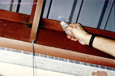
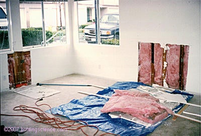
But what happens if it runs into a building paper or a housewrap that breathes? The heat driven vapor blows through it like a hot knife through butter. What is the building paper or housewrap installed over? Probably a gypsum sheathing – highly permeable to vapor. So vapor diffuses right through it. Next comes fiberglass cavity insulation, which can’t stop the vapor – it’s permeable too. The vapor goes all the way in until it hits the plastic vapor barrier. Not a good idea to put a plastic vapor barrier on the inside of a brick veneer wall that sees rain and sun. The vapor condenses on the plastic vapor barrier and runs down the wall to sit in the bottom plate track (Photograph 1). Now we have a full range of problems to choose from: corrosion, mold, odors or staining. You can get the same effect by installing a vinyl wall covering rather than the plastic vapor barrier (Figure 1). Just ask the hotel industry about this practice (Photograph 2).
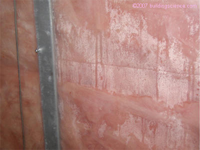
Photograph 1: Interior Polyethylene Vapor Barrier – Condensation from inwardly driven moisture
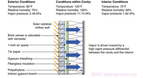
Figure 1: Inward moisture drive due to solar radiation
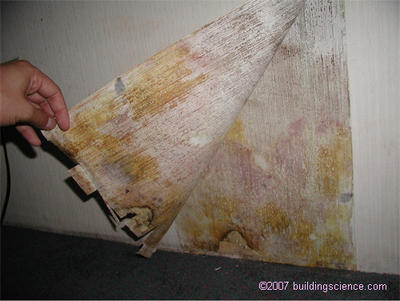
Photograph 2: Vinyl Wallcovering – Mold due to inwardly driven moisture trapped by the vapor impermeability of the vinyl wallcovering
In this example the water started out as a liquid governed by gravity (the rain on the brick veneer) and was pulled into the porous brick veneer by capillarity. It was driven from the brick veneer and converted into a vapor in the airspace behind the brick by the energy added by the incident solar radiation [3]. Once in the cavity it traveled along the concentration gradient and thermal gradient through the wall assembly materials by the process of vapor diffusion until it condensed back into a liquid at the interior of the exterior wall assembly. Once in the liquid form again, it ran down the wall to the bottom plate. Two rules can prevent this common problem sequence:
Rule Number One: Never install a vapor barrier on the inside of a wall assembly, which has a moisture reservoir cladding and a vapor permeable combination of sheathing and building paper.
Rule Number Two: Always vent claddings, especially reservoir claddings. Remember, that in order to vent the cladding you need an air gap behind the material along with an air inlet, an air outlet and a clear path connecting the two.
Clever Water Tricks II – The Old Condensation in the Negative Air Pressure Field Trick
Let’s stay with the rain on the brick veneer over a cavity thing a little longer. Assume that same building is equipped with a dropped ceiling return air plenum (Figure 2). A return plenum operates under a negative air pressure. It’s not likely that the interior gypsum board extends to the underside of the roof/floor assembly and is sealed with a material that is airtight. The usual practice is to shove some mineral wool in the flutes or floor decking above the top of the gypsum board and hope for the best.
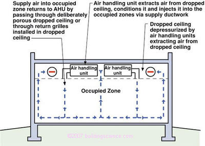
Figure 2: Dropped Ceiling Return Plenum
Given the poor air seal, the negative pressure in the ceiling plenum sucks saturated air out of the wall cavity into the plenum (Photograph 3) where it can condense on piping, ductwork and anything else it contacts that has a surface temperature below its dewpoint (Figure 3). We don’t even need the brick veneer to be saturated to cause this type of a problem. We don’t even need brick – any cladding will do. All we need is outside air to have a dewpoint temperature above the temperature of any surface inside the interior space. Actually, we don’t even need that. Anything that leads to a relative humidity at a hygroscopic surface above 80 percent will do just fine for mold growth. It is alarmingly common to have the de facto fresh air intake of many buildings be the underside of the parapet flashing (Photograph 4).
Photograph 3: Negative Pressure In Dropped Ceiling Return Plenum
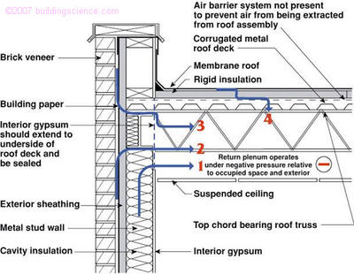
Figure 3: Return Plenum Connected To Exterior Wall
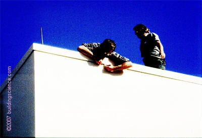
Photograph 4: Parapet Fresh Air Intake
This “sucking on the exterior wall” trick can be accomplished many ways. We don’t always need a dropped ceiling return plenum. We can sometimes just use an interior wall that thinks it’s a duct [4]. The hotel industry and nursing homes are famous for this type of problem. When we couple this with vinyl wall coverings even on interior walls mold grows behind the vinyl. Fan coil units are often enclosed in less than airtight gypsum board enclosures (Photograph 5) and rooftop exhaust fan systems rarely employ airtight ductwork or airtight shafts. The negative pressure fields developed by suction from these fans can extend to exterior walls, drawing air out of exterior cavities inward (Figure 4 and Figure 5).
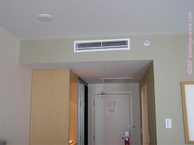
Photograph 5: Fan Coil – Air handler in gypsum board dropped ceiling enclosure
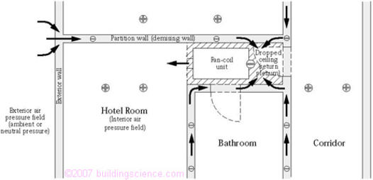 Figure 4: Pressure Field Due to Fan Coil Unit (Plan View)
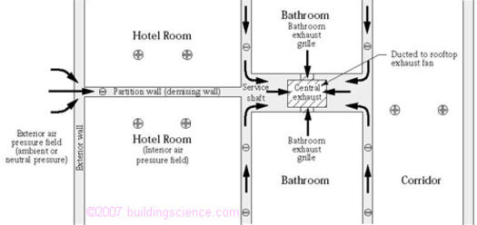 Figure 5: Pressure Field Due to Central Exhaust (Plan View)
In this example the water is pulled out of the cavity or from the exterior ambient air in the vapor form. It is transported by air moving from a higher air pressure to a lower air pressure until it contacts a cool surface where it converts back into a liquid and causes mischief.
Rule number three prevents this problem: Never suck on the exterior building enclosure with your mechanical system. Do not connect drop ceiling return plenums to exterior walls. Make sure that intersecting interior walls neither contain nor are connected to leaking return ductwork or to any leaking exhaust chases or ducts and make sure that all return ducts are sealed tightly with mastic on all joints.
Clever Water Tricks III – The Old Ground Water in the Sand Over the Polyethylene in the Desert Trick
All too frequently we can create a water problem in the middle of a desert. There are many variations. Consider foundations. Normally, we do not have to worry about ground water in the desert. But, let’s plant shrubbery beside a concrete foundation slab. Since we have very little rain, let’s irrigate the plantings so that the ground beside the foundation becomes saturated (Photograph 6). The water then wicks into the porous concrete from the saturated ground by capillary suction. Then it moves upward into the wall assembly (Figure 6). The symptoms are a musty odor inside and if the wall is opened, the bottom plate is typically saturated (Photograph 7).
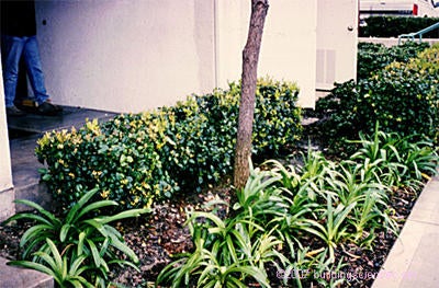
Photograph 6: “Swamp In Desert” Cleverly Located Beside Building Foundation Perimeter
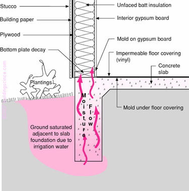
Figure 6: Slab Edge Capillarity
Photograph 7: Wet Bottom Plate – Mold and odors due to capillary rise
This is a fairly simple problem to diagnose and fix. Stop the water. Kill the plants. Or move the plants well away from the foundation perimeter so that when they are irrigated, the saturated ground is not in contact with the foundation. Install a capillary break under the bottom plate of the wall to separate the wood from the wet concrete. Finally, damp proof the edge of the slab with an acrylic latex paint or some other damp proofing material.
The symptoms of this problem can get more complicated with the installation of an impermeable vinyl floor cover or tile flooring. The water can be wicked inwards laterally from the foundation perimeter leading to discoloration of the flooring and loss of adhesion of the flooring. In some cases, the lateral wicking can be many feet. Then the problem is manifested in mold under kitchen cabinets located in “islands” far away from slab foundation perimeters. Water problems in the middle of slab foundations can be due to a water source at the building perimeter as a result of this lateral capillary movement of water. But the solution to the problem is the same – keep moisture from entering the slab by using capillary breaks and by reducing the amount of water soaking the soil near the edge of the foundation.
Now on to a very odd and clearly bad practice that has sometimes even been established in building codes. It is common, west of the Mississippi, to place slab foundations over a sand layer installed over a polyethylene vapor barrier (Photograph 8 and Photograph 9). You rarely see this east of the Mississippi.
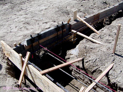
Photograph 8: Sand On Top of Polyethylene – Note polyethylene does not extend to perimeter
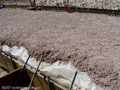
Photograph 9: Madness In The Desert: Note granular layer on top of polyethylene
The sand layer becomes a reservoir for water in the liquid state that enters the sand layer by gravity flow from the top, sides and bottom (Figure 7). Where does this liquid water come from? We often wet cure these slabs. We wet them from the top with sprinklers; we sometimes even pond water on top of them. We often over-irrigate perimeter plantings (see above). Plumbing pipes leak. Even in the desert it sometimes rains during construction. The sources of liquid water are many. The liquid water that inevitably finds its way into the sand layer is both held in the sand layer and redistributed within the sand layer by capillarity (Figure 8). Additionally, due to capillary suction, the liquid water cannot drain out of the sand layer. The only mechanism of drying of the sand layer is upwards through the concrete slab by vapor diffusion (Figure 9).
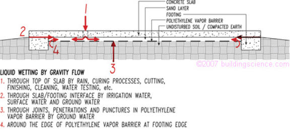
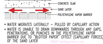
Figure 8: Water Distribution in Sand Layer
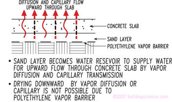
Figure 9: Upward Drying Through Slab
Moisture diffuses upwards through the top surface of the concrete slab as well as through floor surface treatments and leads to mold and other microbial contamination problems.
The rate of wetting of the sand layer by the gravity flow liquid water wetting mechanism is several orders of magnitude greater then the rate of drying of the sand layer by the vapor diffusion drying mechanism. The sand layer becomes a water reservoir that continually supplies water for the upward flow through the concrete slab by vapor diffusion. A couple of hours of liquid water gravity wetting yields a couple of years of diffusion drying.
Picture the sand layer as “blotter paper” that once wetted does not let water drain out of it. The only method of drying available to the “blotter paper” is evaporation. In the case of the sand layer the only method of “evaporation” is upwards through the concrete slab due to the presence of the polyethylene vapor barrier under the sand layer.
So why would anyone want to put sand over plastic under concrete? The following 4 reasons are generally cited for using a sand layer over a polyethylene vapor barriers:
The sand layer controls bleed water with high w/c ratio concrete slabs.
The sand layer reduces curl with high w/c ratio concrete slabs when top-side curing is not controlled.
The sand layer reduces plastic shrinkage cracking with high w/c ratio concrete slabs.
The sand layer protects the polyethylene vapor barrier from punctures.
The first three reasons are based on sound technical arguments. However, each of the first three are based on the condition that the sand layer be prevented from getting wet during the construction process and beyond and are typically associated with floor slabs that are placed “after the building is enclosed and the roof is watertight.” Additionally, the first three are based on the condition that wet curing such as ponding or continuous sprinkling will not occur or that joint sawing using wet methods or power washing will not occur. The first three are also conditional on slab and foundation designs that will not be sensitive to ground water wetting from local water tables and local irrigation.
In other words, the first three reasons are based on conditions that are rarely realized in the real world.
The fourth reason, “puncture protection”, is based on incorrect physics. A sand layer is not necessary to protect polyethylene vapor barriers. Vapor diffusion is a direct function of surface area. Rips, holes, tears and punctures in sheet polyethylene vapor barriers constitute a very small surface area of vapor transmission compared to the total floor slab area. If 95 percent of the surface area of the slab is protected by a vapor barrier, then that vapor barrier is 95 percent effective. This holds true only if air flow or air leakage is not occurring through the vapor barrier. Where concrete is in direct contact with the polyethylene vapor barrier this is the case. Airflow is not occurring. The concrete slab is an “air-barrier” and the polyethylene is the “vapor barrier” – and an effective vapor barrier even if the polyethylene has numerous punctures.
In this example the water enters the sand layer under the slab in the liquid form by gravity. The water is redistributed in the sand layer by capillarity and migrates upward by vapor diffusion.
This leads to rule number four: Never place concrete on a sand layer installed over a polyethylene vapor barrier. Always place concrete in direct contact with plastic vapor barriers. Use a low water-to-cement ratio concrete, less than 0.45, and top cure the slab with damp burlap, just like the old wise concrete types used to.
Conclusions
Water can be tricky to track in diagnosing moisture related building problems because it is constantly changing its form and therefore its behavior. Investigators have to “Get Smart” in order to out-think the water and get to the root of the problem. When faced with a seemingly complex problem, going back to first principles always works.
References
- Kumaran, M.K., Mitalas, G.P., and Bomberg, M.T.; “Fundamentals of Transport and Storage of Moisture in Building Materials and Components”, ASTM Manual Series: MNL 18, Moisture Control in Buildings, ISBN 0-8031-2051-6, Philadelphia, February 1994.
- Straube, J.F.; “Moisture Control and Enclosure Wall Systems”, Doctoral Thesis in Civil Engineering, University of Waterloo, Waterloo, Canada, 1998.
- Wilson, A.G., “Condensation in Insulated Masonry Walls in Summer”, CIB/RILEM Symposium on Moisture Problems in Buildings (NRC 9130), Helsinki, 1965.
- Lstiburek, J.W.; “Pressure Response of Buildings”, ASHRAE/BETEC, Thermal Performance of Buildings VII, Clearwater Beach, Florida, December, 1998.