“Rain is the single most important factor to control in order to construct a durable structure.”
Drainage planes (also referred to as “water resistive barrier” or WRB) are water repellent materials (building paper, house wrap, sheet or trowel applied membranes, foam insulation, coated structural sheathing , etc) that are located behind the cladding and interconnected with flashings, window and door openings, or other penetrations of the building enclosure in such a way as to drain water that passes through the cladding back out to the exterior.
Drainage Plane
Gravity is the driving force in drainage plane function. Gravity is very reliable. Water management techniques that ignore or try to counteract gravity—reverse lapped flashings for example—are bound to fail.
In order for a drainage plane to be effective it must be continuous in the field of the water repellent material and integrated with flashings and to the water management strategies of other enclosure assemblies (such as roofs, foundations, and windows).
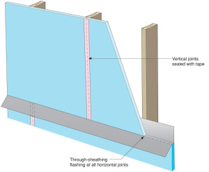
The continuity of the drainage plane is maintained in two ways: 1) through shingle lapping of the materials 2) taping or sealing of material joints in a barrier approach.
Drainage Space
In order for drainage to occur, a drainage space must be provided between the cladding and the drainage plane. The width of this space varies depending on cladding type and function.
Effective drainage of rainwater can occur in drainage spaces as small as 1/16 to 1/8 inch (2 or 3 mm) (e.g. between two layers of building paper in a stucco cladding). Sometimes the drainage space is also called upon to act as a “ventilation space.” Effective ventilation may require spaces as large as 3/4 to 1 inch (20 to 25 mm) depending on the moisture load.
For some cladding systems, e.g. aluminum or vinyl siding, this drainage space is inherent to the cladding system. Similarly brick and masonry veneers have an inherent space, however care must be taken during construction to keep the space clear of mortar so that drainage is not impeded. Products are also available (such as three dimensional plastic mesh products) that help to maintain a clear drainage space.
Wood lap siding has traditionally been installed tight to building paper drainage plane. This creates an intermittent drainage space and is largely dependant on the profile of the siding. This type of installation works well for most instances, however it often reduces the service life of the siding material and has been attributed to some building failures. Ideally wood siding and cementitious lap siding should be installed over vertical wood furring or a plastic spacer mesh to create a vented and drained space behind the cladding.
In stucco cladding, two layers of building paper can provide adequate drainage space. The outer layer of builder paper acts as a bond break between the stucco rendering and the inner layer of building paper. With building paper, the moisture in the stucco causes the paper to swell slightly and wrinkle during application of the stucco. Over time the paper dries leaving small drainage channels between the two layers of building paper. Improved performance can be achieved through the use of a plastic drainage mesh with a filter fabric (usually adhered to one side of the mesh) installed between the stucco renderings and the drainage mesh. This creates a larger and more effective drainage space for the system.
The principle of drainage applies to the design and construction of window and door components in the same way that it applies to walls and openings. Window and door openings should be drained to the exterior using the same principles used in the design and construction of wall assemblies in general. Consult the references listed below or Information Sheet 302: Pan Flashing for Exterior Wall Openings for more on this topic.
Drainage Plane/Water Resistive Barrier Details
Figure 1
Fundamental Rain Water Control
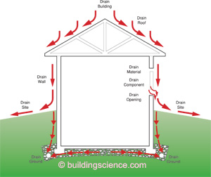
- Drain the site – slope grade away from building
- Drain the ground – foundation perimeter drain
- Drain the building – roof system
- Drain the assembly – drainage plane and water management system
- Drain the opening – pan flashings
- Drain the component
- Drain the material
Figure 2
Shingle Lapped Assembly
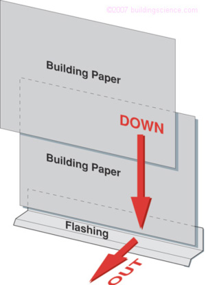
Figure 3
Barrier Assembly
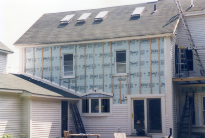
Photograph 1
Water Resistant Sheathing as Drainage Plane

- All joints and seams in sheathing sealed with compatible and durable tape
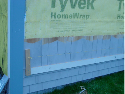
Photograph 2
Wood Furring Strip Drainage Space
- Furring strips fastened to framing through insulating sheathing.
- All openings top and bottom provided with screen to prevent insect entry
Photograph 3
Plastic Mesh Drainage Space
- All openings top and bottom provided with screen to prevent insect entry