Gravity is the driving force behind drainage. The “down” direction harnesses the force of gravity and the “out” direction gets the water away from the building enclosure assemblies, openings, components and materials. In general, the sooner water is directed out the better. Sooner, may not always be practical—such as at window openings where draining a window into a drainage space behind a cladding is often more practical than draining them to the exterior face of the cladding.
The most elegant expression of this concept is a flashing (see Roof to Wall Flashing with Foam Sheathing). Flashings are the most under-rated building enclosure component and arguably the most important. Flashings are integrated with drainage planes creating, for all practical purposes, a flashing for the entire assembly.
Metal flashings on buildings serve a multiple of similar yet slightly different functions.
-
to direct water that has penetrated behind the cladding back out to the exterior (such as wall base flashing), or
-
to protect an interface between two different enclosure elements (such as roof to wall step flashing), or
-
to shed water over protruding building elements (such as window/door/trim flashing), or
- all three.
Flashings are needed wherever a drainage plane is terminated as at a roof edge or bottom of wall, or interrupted as at openings, intersection of assemblies, control joints, or penetrations of the drainage plane. Flashings must not direct water onto another building element in a way that concentrates moisture loading. Flashings are about reducing moisture loading on the building enclosure.
Step Flashing
Stepped flashing is used where a sloped shingled roof intersects a vertical wall. Step flashings are interwoven with the shingles and act essentially as shingles with an upturned leg to allow a transition of the vertical drainage plane of the wall to the drainage plane of the roof. The upturned leg of the step flashing is behind the vertical drainage plane or sealed to it with adhesive membrane and sheathing tape. The bottom leg of the step flashing is placed over the roof drainage plane.
A critical component of step flashings along the run of the roof slope is a kick-out flashing. The kick-out flashing directs water away from the adjoining wall and ensures that the step flashing is not concentrating water on the surface of that wall.
Head Flashings
Head flashings are used to direct water away from openings such as windows and doors. Head flashings should be installed with a positive slope to the exterior. The cladding above the head flashing should never rest on the flashing as this leads to problems with the flashing being bent in the wrong direction and sloped back towards the building. Head flashings should extent laterally past the opening on either side.
Flashing Penetrations
Flanged penetration covers can be readily integrated into a drainage plane. With lapped drainage planes such as building paper, the drainage plane material is place beneath the flanged cover, then the subsequent sheet is lapped over the flanged cover. In the case of drainage plane sheathings or housewraps, the flanged cover is sealed to the drainage plane using appropriate tape as illustrated below.
Cap flashing or other pre-manufactured flashings can provide elegant solutions to drainage plane penetrations. Where flashings need to be site-built from sheet metal, or flashing membranes, the finished installation must follow the fundamental flashing rules of down and out. Flashings must always direct water out over the cladding or drainage plane without openings that would allow water to be directed back into the wall.
Common Flashing Details
Figure 1
Flashing Fundamentals
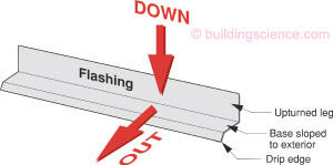
Figure 2
Roof to Wall Flashing with Foam Sheathing
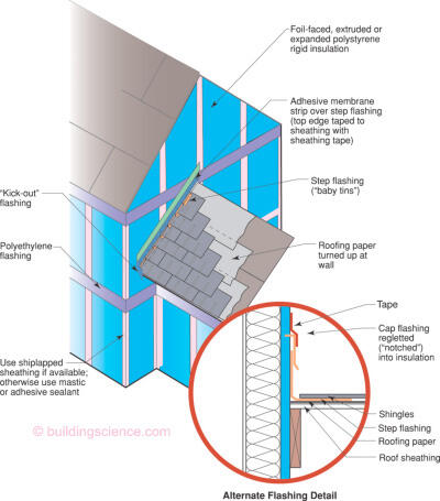

- Upturned leg of step flashing sealed to wall drainage plane with adhesive membrane. Top edge of adhesive membrane is taped to drainage plane with sheathing tape. Alternatively, a cap flashing can be regletted into the foam sheathing with tape forming a transition to the cap flashing.
Figure 3
Head Flashing over Drainage Plane Sheathing
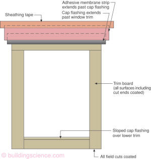

- Layers of the head flashing extend past subsequent layers
- Where the drainage plane is applied over the sheathing, (i.e sheathing itself is not the drainage plane) it should lap over the head or cap flashing
Figure 4
Saddle Flashing
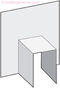

- A saddle flashing should be used for railing attachment and for cantilevered joists and beams penetrating exterior walls
Figure 5
Flanged Penetration
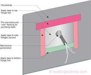

- Tape is applied in order from lower edge to sides to top edge so that it will lap correctly, i.e. shingle fashion
Figure 6
Flanged Penetration with Building Paper
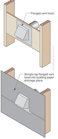

- Lower piece of building paper tucked under flanged vent
- Upper piece of building paper lapped over flanged vent
Figure 7
Flashed Pipe Penetration with Building Paper Drainage Plane
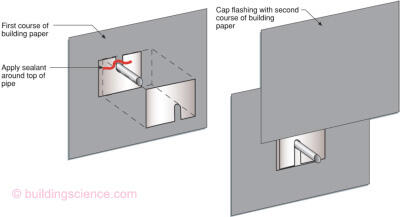

- Pipe flashing is shingle lapped into drainage plane
- With non-lapped drainage planes, the top edge of the pipe flashing is sealed to the drainage plane with sheathing tape
Photograph 1
Improper Head Flashing Slope
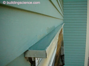

- Improper sloped head flashing directing water back towards the building
Photograph 2
Kick-Out Flashing with Stucco Cladding
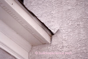

- The kick-out flashing directs water away from the adjoining wall surface
- Step flashing piece above is lapped over kick-out