Stucco and EIFS are common cladding systems that appear similar from the exterior. These systems have very different attributes however. This Digest explains the reasons why face-sealed EIFS are fundamentally flawed as cladding systems for most applications, and describes how drained EIFS can be used successfully in almost all climate zones and exposures. Cracks, lamina deterioration, and movement joints are also discussed.
EIFS and Stucco
Exterior Insulation and Finish Systems (EIFS) are a relatively new cladding system that combine a finish with a layer of exterior insulation. The finish is comprised of polymeric (organic) bonded aggregate and cement reinforced with a glass mesh. Stucco is a cladding made of inorganic-cement (Portland cement and/or lime) bonded sand or earth used for thousands of years. Although these two claddings may look the same, they perform very differently.
Problems
EIFS became very popular in the 1980’s and experienced a significant number of serious failures, almost all related to rain penetration. Early EIFS used a face-sealed approach (defined later). Face-sealed exterior insulation and finishing systems (EIFS) are inherently defective and unfit for use as an exterior cladding system where moisture sensitive components are used without a provision for drainage or in locations and assemblies without adequate drying. Most EIFS of the past were face-sealed systems that by definition had no provision for drainage. The typical system also contains moisture sensitive materials. Specifically, the following moisture sensitive components are used: exterior gypsum board, oriented strand board (OSB) or plywood sheathing, metal or wood studs, fiberglass cavity insulation and interior gypsum board sheathing (Figure 2).
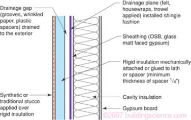
Drained EIFS are significantly different from face-sealed systems in that, by definition, they have a provision for drainage (Figure 3). Unlike face-sealed perfect barrier systems such systems can be successfully used as an exterior cladding system in essentially all climates and exposures. Drainable EIFS are not subject to the same limitations of use as face-sealed or barrier systems. In fact, drainable EIFS are among the most robust and advanced moisture control assemblies available.
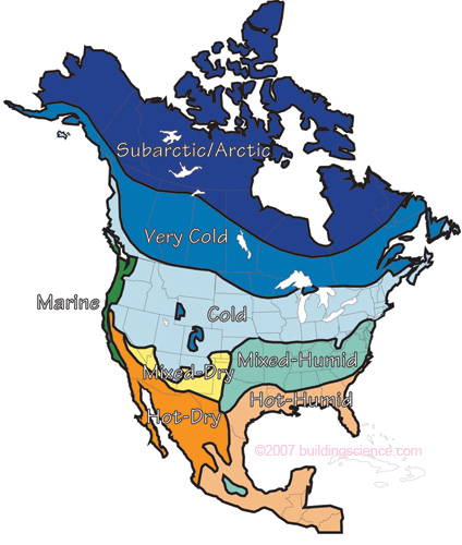
Figure 1: Hygro-thermal Regions
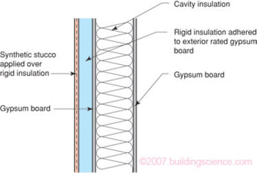
Figure 2: Face-sealed EIFS Assembly
Effect of Climate
The exterior and interior climates in many regions throughout North America provide limited drying potentials due to high relative humidities throughout the year. This is particularly a problem in hot-humid and mixed-humid climates. This limited drying potential provides inadequate drying for EIFS where moisture sensitive components are used without a provision for drainage. Inward drying is essentially eliminated by the installation of interior vapor barriers or impermeable interior finishes such as vinyl wall coverings.
Moisture damage is in essence a rate question. When the rate of wetting is greater than the rate of drying, accumulation occurs. When the quantity of accumulated moisture exceeds the safe or tolerable moisture storage capacity of a material, deterioration occurs. The typical moisture damage in an EIFS assembly is deterioration due to mold, wood decay fungi and corrosion leading to decay, loss of strength and discoloration. The components principally affected are the interior and exterior gypsum sheathing, the metal or wood studs and the fiberglass cavity insulation. Less affected are the EIFS lamina and sealants.
The rate of wetting of a building assembly is a function of exposure, design, construction and operation/maintenance. The rate of drying of a building is a function of the same parameters.
The principal wetting mechanism for EIFS assemblies is rain. Just as all cladding systems, EIFS are sensitive to the frequency and severity of rain. The amount of rainfall deposited on a surface determines the type of approach necessary to control rain. Figure 4 is a map of annual rainfall for North America. This map defines four rain exposure regions based on annual rainfall on a horizontal surface: extreme, high, moderate and low. The rain that must be controlled by walls is rain on a vertical surface. The amount of rain actually deposited on a wall can vary dramatically (by a factor of ten) in a given climate zone depending on height, exposure, overhangs, and surface details. In short, the climate and the architecture defines the amount of rain exposure. For all but the lowest exposures (e.g., the wall of a one storey building with a wrap around porch) face-sealed approached cannot be recommended.
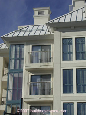
Photograph 1: Architectural details such as overhangs, balconies, and railing connections contribute to the amount of rain deposited in or on a wall.
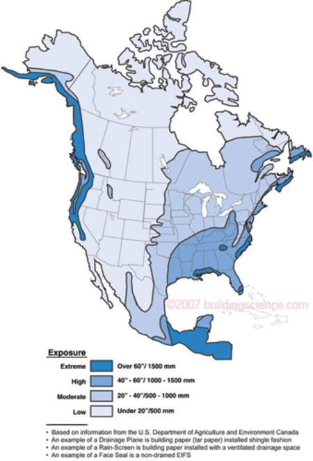
Figure 4: Rainfall Map of North America
Rain Control Strategies
Three broad types of rain control strategies are available for building enclosures (see also BSD-013: Rain Control in Buildings).
- Water managed:
- Storage or reservoir
- Drained
- Perfect barrier
The reservoir or storage approach is traditionally used with heavy, massive, solid assemblies of non-water sensitive materials such as stone, brick, masonry and concrete structures. The drained approach is traditionally used with light, hollow, water sensitive construction such as wood frame, curtain wall and steel frame structures. The perfect barrier approach has been applied to factory-built units, curtainwalls, and some EIFS.
The storage approach assumes that some rain water will pass through the cladding system into the wall assembly. In general, this rain water is stored in the mass of the wall assembly until drying by diffusion, capillarity and air flow occurs to either the exterior or interior. The barrier approach relies on water resistant materials, a significant reservoir or storage capacity, and a balance of wetting potentials with drying potentials. Historically speaking this is the oldest technology used for rain control.
The drained approach also assumes that some rain water will pass through the cladding or face of the wall assembly. However, the majority of this rain water is drained back to the exterior. A drainage plane is installed behind the exterior cladding to facilitate this drainage. This drainage plane requires a drainage space (air gap), flashings, and weep openings to function. The drainage space, which can be as small as the space between two sheets of building paper, allows rain water to drain between the drainage plane and the exterior cladding. The flashing collects the draining water and directs it out through the weep openings to the exterior. The small amount of rain water that does not drain to the exterior, dries by diffusion, capillarity and air flow to either the exterior or the interior as in the storage approach.
The perfect barrier approach assumes that a single layer will control all rain penetration. If this layer is the exterior-most layer, the approach is often labelled “face-sealed.” If the barrier is placed within the assembly, it is termed the “concealed barrier.”
Traditional Stucco
Traditional stucco claddings have successfully employed the water managed approaches, both storage and drained. Traditional stucco rendered on the exterior with a Portland cement based stucco is a classic and successful example of a storage approach to rain control. A vapor permeable paint is often used over the stucco rendering to reduce rain water absorption while still allowing drying to the exterior. Interior finishes are typically vapor permeable and held away from the interior masonry surface to promote drying to the interior. The rain water that enters through the stucco face is harmlessly stored in the masonry wall until it can dry to either the interior or to the exterior.
Traditional stucco using the drained approach (Figure 5) is common to wood frame or steel stud walls that are sheathed with plywood or gypsum board. Two layers of building paper and metal lath are installed shingle fashion over the exterior sheathing. A Portland cement based stucco is then rendered over the metal lath and building papers. The building papers absorb water, swell and wrinkle. After application, the building papers dry, shrink and the stucco rendering debonds from the building papers creating a drainage space. The drainage space is connected to weep screeds or flashings to complete the system. The water that enters through the stucco face is drained back to the exterior by the drainage plane and the weep screeds or flashing system.
Traditional stucco systems recognize the obvious – stucco cracks. Furthermore, since traditional stucco cracks, traditional stucco systems leak. Since traditional stucco systems leak, the leaking rain water must be addressed. This is done either by constructing assemblies from water resistant materials such as masonry and relying on high drying potentials or by using water management – drainage planes, drainage spaces and flashing systems.
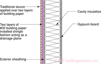
Figure 5: Traditional Drained Stucco Assembly
Many other traditional cladding systems also recognize the obvious – cladding systems leak. Brick leaks, wood siding leaks, vinyl siding leaks, stone leaks, granite leaks, stucco leaks, hardboard siding leaks, precast concrete leaks, curtain wall assemblies leak – everything leaks. Since everything leaks, assemblies are constructed out of water resistant materials or they are drained. This is a fundamental rule of design and construction.
Low-rise buildings with low exposure (overhangs, simple shapes) built in climates with little rain (e.g. less than 20” per year), and lots of drying capacity (dry air and sun) have long been built with little concern for rain control. Almost anything can be built using any type of material. In these situtations, walls don’t get very wet and they dry out quickly. The rate of wetting is low while the rate of drying is high – accumulation rarely occurs and even moisture sensitive materials can be used in a storage approach, and walls with failed perfect barriers rarely exhibit problems.
Traditional construction recognizes something else that is also obvious – it is not possible to rely on perfect workmanship and perfect materials. People are imperfect and materials are imperfect. There are limitations to what can be expected of individuals in the field and there is variation in the quality of materials – from sealants to the grade of wood, from the density of foam sheathing to the permeability of paint.
Face-Sealed EIFS and Sealant Joints
Relying on perfect workmanship and perfect materials to keep rain out, in a location where it rains, is a fundamental flaw in logic. It is contrary to historical experience and contrary to human nature. This is why EIFS are inherently defective and unfit for use as exterior cladding systems where moisture sensitive components are used without a provision for drainage or in locations without adequate drying. Adequate drying will occur in locations with high drying potentials – locations where, in essence, it does not rain much.
Rainwater penetration primarily occurs at joints and penetrations: between the EIFS lamina and windows, through balcony elements, through railings, through windows, through sliding doors, through service penetrations, through interfaces with other claddings, and through the roof system, particularly at the interface with the parapet. Water can even penetrate through large cracks in the lamina itself. That rain water enters should not be a surprise since, for all practical purposes, rain water penetration past the face is impossible to reliably prevent everywhere across the cladding.
Face-sealed perfect barrier EIFS systems are fundamentally flawed because they rely on perfect sealant material installed in a perfect manner to perfectly prepared substrates. It may be possible to install sealant in one joint perfectly – if the surfaces are clean, dry, dust free and the correct sealant, backer rod and gap are provided. Let us also assume good weather, not too cold, not too hot, not raining and the installer is well-trained and motivated by quality not speed. But how about installing sealant perfectly in 10 joints?
Is it possible for a technician to install sealant perfectly in 10 joints in a row? Let us assume perfectly prepared joints: joints that are “backwrapped” properly, with the correct gap. It is probably possible – a conscientious, properly trained, supervised technician could do 10 perfect joints in a row.
Now how about 100 joints? Recall, that the joints must be perfectly prepared and that this preparation is dependent on other trades and technicians: the window installation contractor and the foam and lamina application technician. I think most rational people would have a problem with 100 perfect joints. But the requirement for 100 perfect joints is nothing – a drop in the bucket for what is required. How about 1,000 perfect joints? Or 10,000 perfect joints? Now we are getting just a little bit outrageous. Yet, this is what is required of EIFS constructed with moisture sensitive components without provision for drainage or adequate drying.
But on the subject of joints, we are just beginning. How do you select the sealant? Well, the material must adhere to the lamina, must be resistant to ultra-violet light; the base coat bond strength to the rigid insulation (EPS) must be greater than the sealant bond; and the material also has to be affordable. Does such a sealant exist? Some come close to meeting these requirements, but they are not often used. Oh, by the way, all the windows leak. So even if one achieves the impossible, water will penetrate behind the perfect sealant at penetrations, and hence be trapped in the assembly.
How long should this joint last? How can you tell when the sealant in the joint needs to be replaced or how can you tell when the joint needs to be rehabilitated? How do you replace sealant in joints? How do you prepare the surfaces to take new sealant? If you attempt to grind the surfaces clean, you risk damaging the reinforcement. You think installing the sealant perfectly the first time was difficult – how about after the building has aged a decade? Now what? What indeed.
It is the new millennium and the arguments around these questions continue to rage – no consensus exists within the EIFS industry – consensus certainly does not exist among consultants engaged in the rehabilitation of EIFS clad buildings.
Any system that relies on perfect joints, sealed perfectly, with perfect windows is fundamentally, inherently defective. The system, if it is constructed with moisture sensitive materials in a climate where it rains and has a high humidity, is destined for problems.
Cracking
Traditional stucco cracks due to drying shrinkage or hygric stresses, embrittlement due to aging, and building movement. EIFS laminas do the same thing for essentially the same reasons. It is not possible to prevent traditional stucco from cracking. The same holds true for EIFS laminas. In both cases, the size of the cracks are controlled to manageable levels.
If drying shrinkage or hygric and thermal stress were not an issue in EIFS laminas, mesh reinforcing would not be necessary. The function of mesh reinforcing is to distribute the hygric stresses throughout the lamina rather than allowing stress relief to occur at a single location such as a large crack. In the most fundamental sense a crack is stress relief. When cracking begins to occur, an additional function of the mesh reinforcing is to promote micro-cracking – many tiny cracks rather than fewer larger cracks, and to limit crack propagation – short cracks rather than long ones. More mesh reinforcing provides more effective distribution of hygric stresses, effectively promotes micro-cracking and limits crack propagation.
Unfortunately, the use of fiberglass mesh in an alkaline environment leads to the deterioration of the fiberglass mesh. To compensate for this, the mesh is coated with plastic and the alkaline environment is buffered chemically. However, prolonged exposure of the lamina to moisture eventually leads to a loss of strength of the fiberglass mesh. This mechanism of deterioration can only be slowed, not stopped or prevented. There is no known solution to this problem. To further compensate for this problem, more mesh reinforcing and thicker mesh reinforcing is used. The logic being: if it’s going to get weaker, make it stronger than you need initially, so that later it will still be strong enough. The flaw in this logic is the definition of “later.” Does later mean 1 year, 3 years, 5 years, 10 years, 25 years or 50 years? “Later” also depends on exposure. Ten years in Las Vegas is very different from 10 years in Columbia, SC.
Unfortunately, more mesh reinforcing leads to a thicker lamina, which decreases the elasticity of the system. To compensate for this problem, the elasticity of the system is increased by increasing the acrylic content. However, as the acrylic content is increased the permeability of the lamina is decreased while the sensitivity of the lamina to ultra-violet light (solar radiation) is increased. A decrease in permeability, of course, leads to a reduction in drying to the exterior.
The exposure to ultra-violet light leads to embrittlement and a decrease in elasticity of the system. The acrylic content also interferes with hydration and makes the lamina more sensitive to carbonation – a reaction with atmospheric carbon dioxide – that leads to embrittlement and a decrease in elasticity.
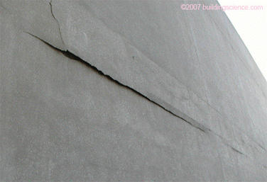
In short, as the system ages, the lamina becomes more brittle and subject to cracking. Some EIFS laminas crack sooner than others, but they all eventually crack. The cracks are due to hygric and thermal stresses, embrittlement due to aging, and building movement. The cracks in EIFS laminas are often found initially at reveals and at window openings. The hygric stresses and building movement stresses typically concentrate at locations where there is a change in thickness, a change in direction or at a termination such as an opening.
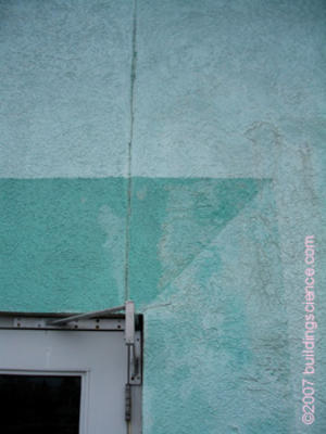
Photograph 2: Cracks in EIFS laminas are often found initially at reveals and at window openings.
Movements
Taking into account hygric stresses and embrittlement due to aging is one thing. Building movement is an entirely different – and more serious matter. All buildings move. Tall and large buildings move more than short and small buildings. Since all buildings move, control joints are necessary. If control joints are not provided, the building provides its own in the form of cracks.
Wood framing shrinks in the cross-grain direction during the drying of initial construction moisture, and continues to expand and contract in response to changes in local relative humidity. Cross-grain is often concentrated at rim joists, top and bottom plates, and around heavy framing at openings. If EIFS is adhered to a wood-framed building, these movements must be anticipated and accommodated. Typical shrinkage is in the order of 1/2" to 3/4” per storey near the rim joist.
Photograph 3: Frame shrinkage at the rim joist of this wood-framed building caused the stucco to buckle.
Steel framed buildings experience most movement at long-span beams. Many engineers design beams that allow deflection of 1/360th of span: that is a 30 ft span steel beam should be expected to deflect as much as 1” at midspan.
Tall concrete frame buildings are subject to frame shortening due to the mechanism of concrete creep, a fundamental characteristic of concrete experiencing loading over an extended period of time. The weight of a tall concrete building causes the columns to shorten by swelling. In order to take this into account, control joints are typically provided through the cladding system at every floor.
Summary
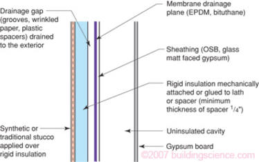
EIFS can provide an attractive lightweight and energy-saving cladding for a building. However, experience has clearly shown that rainwater must be managed, and face-sealed perfect barrier approaches (reliance on exposed sealants) cannot provide acceptable rain control or durability. To allow for drying of incidental moisture, such assemblies also should not contain interior vapor barriers or impermeable interior finishes. An important exception to this latter requirement is where the drainage plane is also a vapor impermeable air barrier membrane and the interior framing cavities are uninsulated (Figure 6).