This digest reviews the moisture control principles that must be followed for a successful insulated retrofit of a solid load-bearing masonry wall. Two possible approaches to retrofitting such walls are presented and compared.
Introduction
Reducing the energy consumption of buildings has become increasingly imperative because of the combined demands of energy security, rising energy costs, and the need to reduce the environmental damage of energy consumption. A significant amount of research has developed guidance and technology to assist designers and owners significantly reduce the energy consumption of new buildings. However, a vast stock of existing buildings, the great majority of which have poorly insulated enclosures, exists. Improving the energy performance of this stock of buildings will be a very important part of transitioning North America from an imported fossil fuel dependent region, to a low-carbon, self-sufficient economy.
Upgrading, renovating and converting buildings to new uses involve numerous challenges. A socially, culturally, and economically important class of buildings is load-bearing brick masonry buildings, typically built before the Second World War. Adding insulation to the walls of such masonry buildings in cold, and particularly cold and wet, climates may cause performance and durability problems in some cases. Many of the same principles apply to the interior insulation of the CMU walls with masonry facing widely used for the decades after WW2.
This digest reviews the moisture control principles that must be followed for a successful insulated retrofit of a solid load-bearing masonry wall. Different possible approaches to retrofitting such walls are presented and compared.
The Moisture Balance
The primary concern with insulating older load bearing masonry buildings in cold climates is the possibility of causing freeze-thaw damage of the brickwork and decay in any embedded wood structure. Both concerns are related to excess moisture content and hence a review of moisture in building enclosures is appropriate.
For a moisture-related problem to occur, at least five conditions must be satisfied:
a moisture source must be available,
there must be a route or means for this moisture to travel,
there must be some driving force to cause moisture movement,
the material(s) involved must be susceptible to moisture damage, and
the moisture content must exceed the material’s safe moisture content for a sufficient length of time.
To avoid a moisture problem one could, in theory, choose to eliminate any one of the conditions listed above. In reality, it is practically impossible to remove all moisture sources, to build walls with no imperfections, or to remove all forces driving moisture movement. It is also not economical to use only those materials that are not susceptible to moisture damage. Therefore, in practice, it is common to address two or more of these prerequisites so as to reduce the probability of exceeding the safe moisture content and the amount of time the moisture content is exceeded.
All enclosure design requires a balance of wetting and drying (Figure 1). Since wetting occurs at different times than drying, storage bridges the time between wetting and drying. If a balance between wetting and drying is maintained, moisture will not accumulate over time, the safe moisture content will not be exceeded, and moisture-related problems are unlikely. The storage capacity and the extent and duration of wetting and drying must, however, always be considered when assessing the risk of moisture damage.
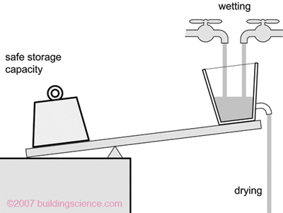
Figure 1: The moisture balance analogy.
The four major sources of moisture for the above-grade building enclosure are (Figure 2):
precipitation, especially driving rain,
water vapor in the air transported by diffusion and/or air movement through the wall (from either the interior or exterior),
built-in and stored moisture, and
liquid and bound ground water.
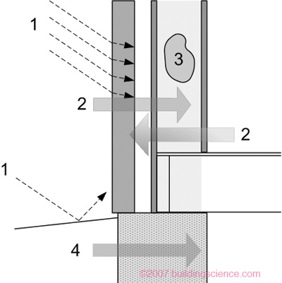
Figure 2: Moisture sources and mechanisms for an arbitrary enclosure wall.
An assembly’s drying potential is an important factor in assessing its vulnerability to moisture problems. Moisture is usually removed from an enclosure assembly by (Figure 3):
evaporation of water at the interior and exterior surface transported their by capillary suction through microscopic pores;
vapor transport by diffusion (through microscopic pores), air leakage (through cracks and holes), or both, either outward or inward;
drainage through gaps, cracks and openings, driven by gravity; and
ventilation (ventilation drying), the intentional flow of air behind the cladding.
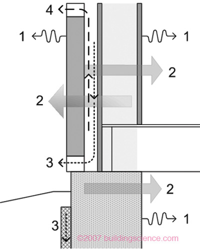
Figure 3: Moisture removal mechanisms.
Why Retrofit Load-Bearing Masonry Walls
The enclosure walls of many older buildings are comprised of several wythes of interlocking masonry, cement, lime or cement-lime mortar. The interior may be exposed masonry but is often completed with parging, wood lath, and/or plaster. In institutional buildings, particularly those built later in the period, one or more wythes of hollow clay or terracotta tile may be added to the interior and finished with plaster. The hollow inner wythes provided both increased insulation as well as space to run plumbing services. Beginning around the second world war, the inner layer of masonry was often comprised of concrete masonry units bonded with exterior masonry facings.
Load bearing brick masonry buildings have the potential for long term durability – it is for this reason that many still exist and are available for renovation and conversion after service lives of well over 50 to 100 years. However, the realities of escalating energy costs, increasing standards for occupant comfort, and the unacceptability of environmental damage due to excessive space conditioning energy losses means that modern renovations should incorporate means of reducing heat flow across the enclosure.
Load bearing brickwork of the past has a wide variety of thermal properties, but common moderate density brickwork (80 to 110 pcf) can be assumed to provide an R-value of from R0.25 to R0.33 per inch. Higher density brick (over 125 pcf) has a lower thermal resistance, about 0.15/inch. Hence, a three wythe (12”) thick wall, provides an R-value of between 3 and 4 plus surface heat transfer coefficients (“air films”) of another R1. If the masonry becomes wet, the R-value drops. A CMU wall with an outer bonded brick wythe has similar levels of performance. This level of insulation is too low for many practical purposes and can even lead to condensation problems if interior humidity levels are kept too high. This is especially the case if a buildings use is changed to a museum or gallery space. Even changing a warehouse to a loft apartment, however, may change the interior conditions sufficiently to cause a problem. Hence, for many reasons, the decision is often made to add insulation to the walls during conversion and renovations, as it is possible with the least disruption at this time.
To ensure that the goals of comfort, energy-efficiency, and durability are met, windows, roofs, basements and airtightness must also be included in any evaluation of the potential of a building retrofit. Major improvements in the performance of these other building enclosure components can significantly enhance overall building performance.
In many cases, the addition of thermal insulation, the reduction in air leakage, and high performance windows not only reduces energy consumption, improves comfort, and avoids interior surface condensation, it also allows smaller, less architecturally intrusive and less expensive HVAC systems be installed.
Exterior Insulation Retrofits
From a building science perspective, exterior insulation retrofits offers the easiest, largest, and lowest risk approach to improving enclosure thermal resistance, airtightness, and rain penetration resistance. At the same time, exterior enclosure retrofits enhance the durability of the existing wall more than any other approach (by maintaining it a constant temperature and eliminating all sources of wetting) and ensure the continuity of all control layers. Essentially any level of performance can be achieved with an exterior retrofit as the existing enclosure is used merely as a support structure.
However, there are many reasons why exterior insulation retrofits cannot be used including, of course, the need to protect the aesthetic value of the exterior façade of the building.
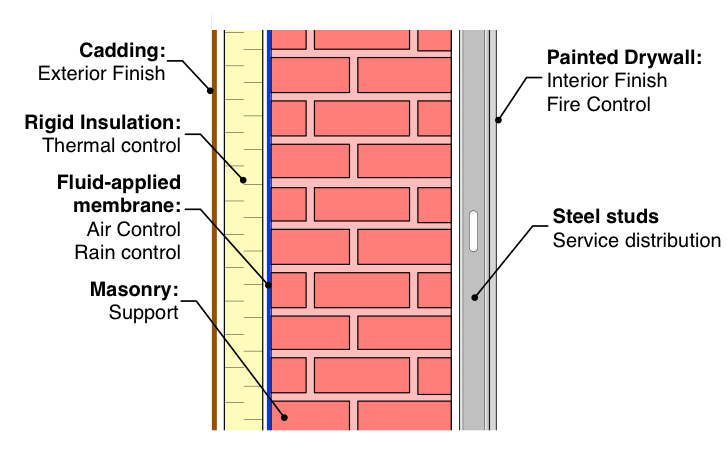
Figure 4: Exterior insulation retrofits are the preferred building science solution.
The Potential for Moisture Problems in Interior Retrofits
Renovating any wall can disrupt the moisture balance and there are examples in practice where this disruption has resulted in damage or performance problems. The damage mechanisms of concern are primarily freeze-thaw and salt subfluorescence. Both of these mechanisms are only a problem in cold weather, and the most dangerous one, freeze-thaw, can only occur at temperatures well below freezing while the brickwork is essentially saturated. To avoid moisture related damage, the balance should be explicitly considered during the retrofit design process (Straube et al 2012).
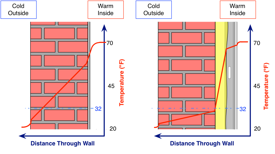
The addition of insulation to the interior of a load-bearing masonry wall will lower the temperature gradient across the masonry and reduce the difference in temperature between the masonry and the exterior air (Figure 5). Both of these changes reduce the drying capacity of the masonry (in particular, the diffusion drying capacity through the masonry is reduced, and the surface evaporation can be slowed.) However, capillary flow is by far the most powerful moisture redistribution mechanism and it is essentially unaffected by insulation.
Water that wicks to the interior face of the now insulated interior face of the masonry can still evaporate from this surface to the interior through the interior insulation and finishes during warmer weather (if the vapor permeance of these interior layers allows it).
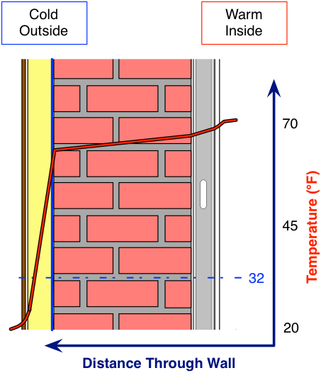
Since the reduced drying capacity could result in higher moisture contents (not necessarily unsafe levels, but one often does not know the safe level with any precision) it would be prudent to also simultaneously reduce the wetting of the wall (ideally, by an equivalent or greater amount) to restore the moisture balance. Hence, an interior insulation retrofit of a masonry building requires a careful assessment of wetting mechanisms. The benefit of exterior retrofits on durability can be considered by comparing the resulting temperature gradient (Figure 6).
In the last decade the evaluation of brick and stone masonry freeze-thaw resistance has developed significantly. Research work has resulted in testing and modeling techniques that allow one to quantify the degree of freeze-thaw resistance (Mensinga et al 2010, 2014, Lstiburek 2011). Testing and assessment allows the team to quantify the risk of freeze-thaw damage in service after an interior retrofit and is now routinely conducted by the RDH Building Science Laboratories.
Wetting Mechanisms and Their Control
Wetting, as described above, can occur from rain wetting (especially at poor surface drainage features), at-grade wetting (from the earth, snow melting, poor surface drainage). After insulation air leakage condensation and vapor diffusion condensation may become important. All need to be considered (Figure 7).
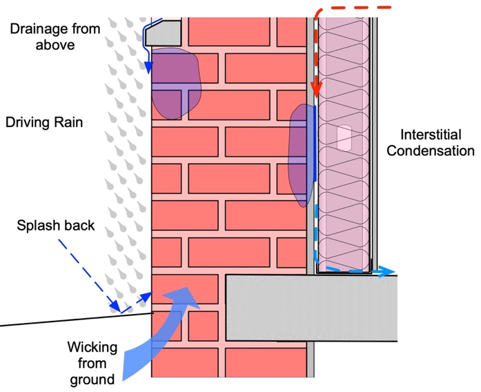
Figure 7: Common solid masonry wall wetting mechanisms.
The largest and most intense wetting that an existing building tends to receive is that of driving rain deposition and concentration. The locations which have the highest intensity of wetting (often in the range of 10 to 100 gallons per square foot per year in the Northeastern part of North America) are the bottom corners of window openings (since windows drain and concentrate water on the lower corners) and at grade (if drainage details are not properly provided for). The control of surface rain water flow is the most critical aspect of controlling the moisture content of the masonry. Hence, reducing the wetting at these locations by the provision of projecting window sills and base drainage can often reduce wetting of the most critical areas far more than the reduction in drying caused by insulating. The role of overhangs (projections of as little as 1” make a material difference to wetting), belt courses, and projecting drips edges along window sills and pilaster tops cannot be underestimated.
The addition of insulation to the interior also adds the potential for a new wetting mechanism – condensation due to air leakage. Since any insulation or new interior finishes will reduce the temperature of the interior face of the masonry in winter, any interior air that contacts this face could condense (see Figure 5).
Given sufficient air leakage and sufficiently high indoor relative humidity this condensate can accumulate faster than it can dry, and the interior face of the masonry will become saturated at the same time the inner surface will often drop below freezing. To control the potential moisture damage, including freeze-thaw damage, an airtight layer to the interior of the insulation should be provided.
Finally, insulating masonry on the interior can increase the potential for diffusion-driven condensation wetting. Some vapor diffusion control is needed if both highly vapor permeable insulation is used and the interior space humidity rises too high during cold weather (above about 30% to 40% RH in cold climates). In most cases, however, the commonly specified vapor diffusion barrier of under 1 US perm is not needed. In fact, low permeance interior finishes and barriers can be detrimental to the performance as such vapor barriers resists or eliminate the potential for inward drying.
The required control of vapor diffusion wetting can usually be provided by typical latex paint, semi-permeable insulation products, smart vapor retarders (products that reduce their vapor permeance in winter and increase it by an order of magnitude in summer) and other similar materials. In general, the optimal level of vapor control required can be easily calculated for specific building exposures and climates using dynamic one-dimensional hygrothermal analysis methods. (We have found that the most accurate and appropriate tool is often WUFI).
Problematic Retrofit Strategies
A common scheme involves drywall on a steel stud wall filled with batt insulation (Figure 5). A small (from ¼” to up to a 2”) air gap, may be intentionally installed on the inside of the existing masonry wall or one can accidentally form because of the dimensional variations implicit in existing masonry buildings. The drywall finish often acts as the air barrier in this situation, and either paint, kraft facings, polyethylene sheet or aluminum foil backing acts as a vapor control layer. (Note that multi-wythe masonry is usually quite air permeable and is not in itself sufficient as an air control layer). There are numerous serious problems with this approach.

First, there is a high likelihood of condensation and mold growth in the wall. As can be seen from Figure 9, if the interior conditions vary between 68 F/25%RH and 71 F/35%RH, the dewpoint temperature will vary between 30 and 40 F. Hence, when the back of the masonry drops below these temperatures (which are likely during cold weather) condensation would occur if airflow behind the masonry were to occur. If higher interior humidities and colder outdoor temperatures are experienced, serious condensation is likely with even very small leaks past the drywall air barrier. Compounding this concern is the common propensity of pressurizing commercial and institutional buildings. This practice is intended to prevent comfort problems due to drafts through uncontrolled air leaks, but it also ensures that air will leak outward in sufficient volumes to cause damaging quantities of condensation on the back of the cold insulated masonry.
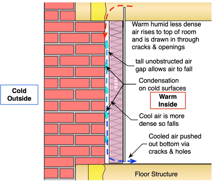
Figure 8: Concept drawing of stud and batt interior retrofit.
If steel studs are used, this approach will not provide insulation to the desired level. Steel studs are thermal bridges, and in the scenario given, are theoretically capable of providing only about R-6 (less if the floor slabs are included). In practice, installing batt between studs with no backing is very difficult, and it is almost certain that the batts will not be properly installed. Finally, air may loop within the insulation via the air gap between the masonry and the batt reducing the R-value even further and encouraging condensation.
Hence, this scheme suffers from a number of limitations – it does not provide a reasonable level of insulation, it increases winter time wetting during the coldest weather (the same period during which there is a risk of freeze-thaw damage) and creates a mold and indoor air quality risk. Given the serious limitations and the questionable benefits of this scheme, it cannot be recommended for any interior insulation retrofits.
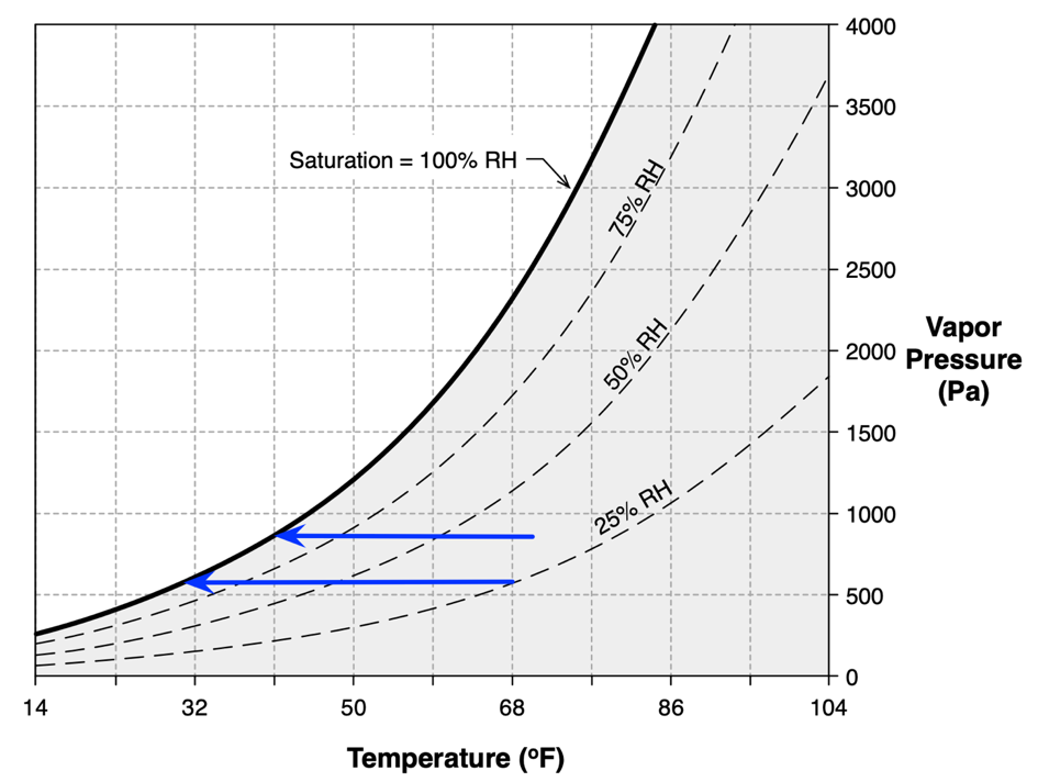
Figure 9: Temperatures at which condendsation can occur.
Semi-Permeable Foam Insulation
A more successful approach involves spraying an airtight insulating foam directly to the back of the existing masonry (Figure 10). The interior finishes must all have high vapor permeance or be back-vented. This retrofit has the advantage that all air leakage condensation is strictly controlled, and rough and out-of-plane masonry walls are accommodated. The use of spray foam also acts as a moisture barrier, as any small amount of incidental rain penetration will be localized and controlled. Hence, interior finishes will be protected as water will not run down and collect at floors penetrating the insulation. Water that is absorbed into the masonry can wick to the outside (where is will evaporate) or wick to the inside, where it will diffuse through the semi-permeable spray foam and interior finishes.
The application of 2 to 4” of foam after a steel stud wall has been installed is straightforward. The empty stud space is ideal for distribution of services and allows the easy application of a drywall finish (required to provide fire protection to the foam). The steel studs should be held back well over 1” from the wall (3” is recommended) to allow foam to be installed and adhere to the masonry at all spots and to control thermal bridging and the moisture nanoclimate experienced by the outer flange of the studs.
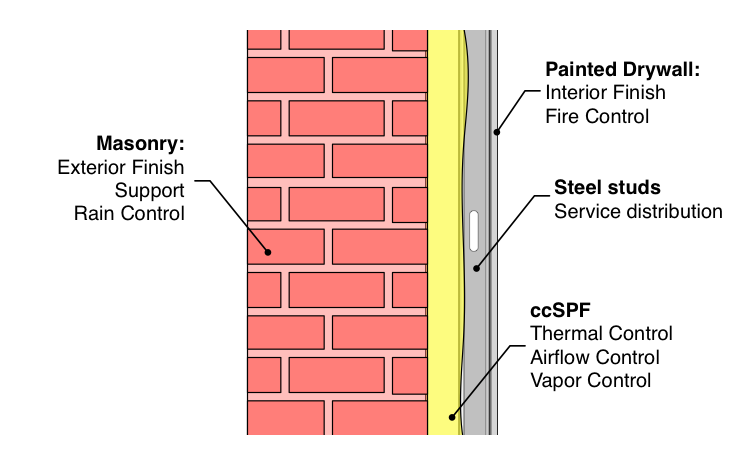
The use of this approach raises the question of the choice of interior vapor permeance for the foam. In general, the interior layers should be chosen to have the highest vapor permeance possible while also avoiding wintertime diffusion condensation wetting. This strategy allows the highest level of inward drying during warmer weather. Closed-cell spray-foam also has sufficient vapor diffusion resistance to manage cold-weather condensation at the brick-foam interface and control potentially damaging inward vapor flow during solar heating of wet masonry. Closed cell polyurethane foam is generally a good solution for thinner applications (2” of closed-cell 2 pcf polyurethane foam has a permeance of about 1 perm and a thermal resistance of about R-12), but open-celled semi-permeable foams (5” has a permeance of about 13 perms and a thermal resistance of almost R-20) can be an acceptable choice for larger thickness if the interior is kept at a low humidity during winter and the outdoor temperature is not too cold. Hygrothermal simulation can be used to identify the proper materials for a particular application.
In many cases rigid foam board insulation of various types has been used as the interior retrofit. For thin layers of insulation, a semi-permeable foam such as extruded polystyrene or unfaced polyisocyanurate can be used, but for thicker layers the more permeable expanded polystyrene board is preferred. This method has been used successfully, but is more difficult to build as it requires great care in ensuring that the board is firmly in contact with the masonry (any gaps may allow convective loops to transport moisture and heat) and that a complete air barrier is formed (taped and/or sealed joints).
Addressing Structural Penetrations
The floor structure inevitably penetrates into, and rests on the masonry walls in these buildings. Occasionally this occurs at pilasters, but it is more common for either large wood beams or concrete slabs to transfer the floor loads to the walls. These penetrations interrupt the continuity of thermal, air and water control. The biggest concerns relate to the potential impact on the durability of the floor after the walls have been insulated (Ueno 2015).
When the structural connection is via concrete slabs, the there are no real durability concerns. However, the conductive concrete can cause sufficient heat loss to make the interior surfaces of the concrete cold. Depending on the interior finishes, the exterior temperature, and the interior relative humidity, surface condensation may become a problem. There are a number of solutions if thermal bridging becomes a problem, including topical and targeted application of heat and/or reduction in interior humidity as well as insulation strategies. Two-dimensional heat flow analysis is an invaluable tool for assessing the impact of surface temperatures and heat flow.
The most challenging scenario is one in which wood beams penetrate the new interior finish and rest in pockets within the masonry. The goal must be to reduce all air leakage which carries moisture into this cold beam pocket. Providing ventilation to this space is almost certain to cause condensation, not avoid it. However, it is desirable to allow some small amount of heat to flow into this space, as this will drying the wood relative to the colder (as it is better insulated) masonry around it. If the beams are as infrequently spaced as 6 or 8 feet then the approach shown in Figure 7 is recommended – that is, air seal caulking and foam is provided around the beam and thinner interior insulation would be used at this location. In some cases, small heat sources can be provided in the beam pockets via highly conductive metal wedges driven alongside the beams.
Alternative Methods
Mineral Fiber Insulation
The use of semi-permeable foam insulation in contact with the back of the existing masonry is the most common successful strategy for interior insulation retrofits. However, for numerous reasons it may be necessary or desirable to use mineral fiber insulation. There is less successful experience with this method, but emerging materials and techniques offer the potential for low-risk and high-performance retrofits. One recommended approach is shown in Figure 11.
A fluid-applied, vapor-permeable air and water barrier should usually be applied to the back of the masonry when board insulation is used, especially mineral-fiber board, because the insulation is not able to stop liquid water migration. The adhered membrane prevents any small and localized water leakage from penetrating, draining, and collecting at floor penetrations. The fluid-applied membrane also acts as the primary air barrier, while being sufficiently vapor permeable to allow water vapor to move in either direction.
Semi-rigid board insulation can be attached with adhesives or mechanical attachments (such as impaling pins or screws with insulation washer). If adhesives are used, the boards should be attached with continuous horizontal grooves patterns to limit convection.
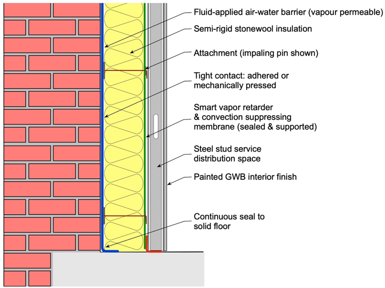
Figure 11: Interior retrofit using mineral fiber insulation.
Interior air flow resistance is also required to control the risk of natural convection. Sufficiently dense mineral fiber insulation pressed tight to the masonry avoids gaps, but joints between boards still offer a path (which can be managed by using two layers of insulation with offset joints between layers). If the insulation is too dense it will not compress around the inevitable rough surface of the exposed masonry (the masonry can occasionally be made smooth by the application of a lime mortar or high-build air-water barrier).
Controlling vapor diffusion is also a challenge with this type of retrofit. Mineral fiber insulation offers very little resistance to vapor diffusion. Without additional vapor resistance, condensation at the interior-face of the masonry will likely occur in cold weather. One can purchase aluminum foil-faced boards, but these have such low vapor permeance that condensation on the outward-facing back of the foil (often paper based and excellent mold food) is a real risk of wet masonry heated by solar exposure.
An ideal solution is the use of a smart vapor retarder: such a membrane can be taped and made continuous as a convection barrier (which will be exposed to modest pressure differences), controls outward diffusion during winter weather, and yet allows inward drying during summer conditions (provided permeable or back-vented interior finishes are used).
Drainage
In some cases the masonry may be sufficiently damaged that rain penetration can be expected. If exterior repairs and re-pointing cannot control this type of rain leakage, a drainage space may in exceptional circumstances be necessary behind the load-bearing masonry. Forming a drainage gap and installing a drainage plane is not difficult, but achieving the required, and critical, flashing details can be a formidable challenge (particularly around structural floor penetrations). If this approach is taken, it is still critical to provide very good airtightness while also avoiding convection of air to the interior despite the deliberately inserted drainage gap.
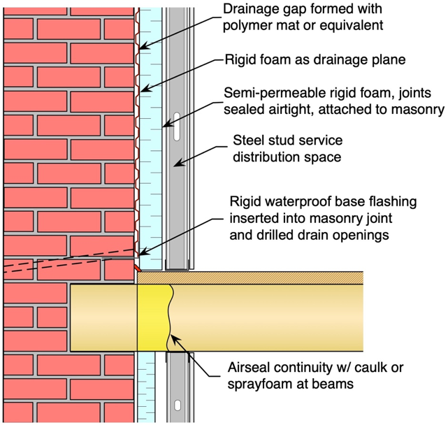
Figure 12: Interior retrofit with drainage.
Drainage of the area of the wall is easy to achieve, but collecting and draining any collected water is very difficult: the challenge of collecting the water in a flashing trough and directing it outward through drain openings entails a high risk of failure. In most cases retrofitting a load-bearing mass wall into a drained wall is not recommended because of the risk, and difficulty. Interior water barriers and exterior detailing should be the focus to control rain penetration.
Active Solutions for High Humidities
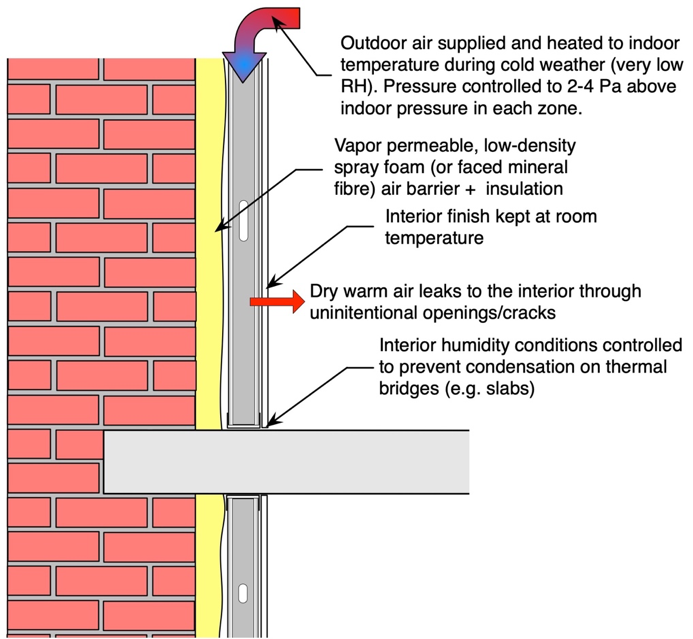
For applications that require a high (over about 40%) relative humidity during the winter, it may be necessary to control airflow by pressurizing the space between the insulation and the interior finish with low humidity air (Figure13). This also allows for thinner layers of insulation to be applied (as the airflow ensures that the interior finishes are at interior temperature regardless of the heat flow through the wall). As the air next to the insulation layer is very dry, it allows highly vapor permeable mineral fiber insulation to be chosen and encourages evaporative drying to the interior during the entire year, not just summer. The most common choice of air supply for this application is the exterior air during cold weather, heated to interior temperatures: mechanical dehumidification is expensive and producing low humidity during cold weather is a challenge, whereas heating the outdoor air produces very dry air very inexpensively. The heated air supply is only used when the dewpoint temperatures outside are below room temperature dewpoint temperatures.
This method of interior retrofit is the most complex, the most expensive, and the most energy intensive. However, it is chosen on occasion because it also allows the most inward drying and changes the moisture balance the least of all options while allow for what would otherwise be dangerously high interior humidities. The same approach can be used at windows by the addition of a single pane indoor storm window, avoiding condensation completely and ensuring indoor comfort.
Summary
Insulating load bearing masonry buildings on the interior in a cold climate is often required to meet human comfort requirements, environmental goals, and cost targets. Many such interior retrofits have already been successfully completed in cold climates by the use of a continuous insulation layer combined with attention to interior airtightening and exterior rain shedding details.
The use of semi-permeable foam insulation in full contact (or adhered) to the back of the existing masonry is the most common successful strategy for interior insulation retrofits in North America with an excellent track record of success. This method also has the advantage of being one of the most practical to achieve under field conditions. The use of air and vapor-permeable semi-rigid board insulation (foam or mineral fiber) can be successful if excellent airtightness is achieved and convection is suppressed, and often requires a vapor-permeable fluid-applied air-water barrier on the interior masonry surface.
To ensure that the goals of comfort, energy-efficiency, and durability are met, windows, roof, basement, and airtightness must also be included in a building retrofit strategy. Major improvements in the performance of these building enclosure components can significantly enhance the overall building performance.
To further reduce the likelihood of moisture problems in the building enclosure, the mechanical systems should be designed and commissioned to avoid any positive pressurization of the building. Indoor humidity also needs to be controlled, particularly in cold weather and colder climates.
References
Lstiburek, Joe. “Building Science Insight #047: Thick as a Brick”, May 2011. Available at http://www.buildingscience.com/documents/insights/bsi-047-thick-as-brick
Mensinga, P., Straube, J.F., Schumacher, C.J., “Assessing the Freeze-thaw Resistance of Clay Brick for Interior Insulation Retrofit Projects”, Proc. Buildings XI, Clearwater Beach FL, Dec 2010.
Mensinga, P., DeRose, D., Straube, JF. “A Test Method to Identify the Onset of Freeze-Thaw Deterioration in Masonry”, ASTM STP 1577, Ed. Michael Tate, West Conshohocken, PA, 2014.
Straube, John Kohta Ueno, and Christopher Schumacher. “Internal Insulation of Masonry Walls: Final Measure Guideline”.US DOE Building America Report, July 2012. Available at http://www.nrel.gov/docs/fy12osti/54163.pdf
Ueno, K., Straube, J.F., vanStraaten, R., “Field Monitoring and Simulation of a Historic Mass Masonry Building Retrofitted with Interior Insulation”, Proc. Of Buildings XII, Clearwater Beach, FL., Dec. 2013.
Ueno, K. “Field Monitoring of Embedded Wood Members in Insulated Masonry Walls in a Cold Climate”, BEST Conference Building Enclosure Science & Technology 4, Kansas City April 2015.