Controlling rain is the single most important factor in the design and construction of durable buildings and in the control of mold. Drainage planes are used in the design and construction of building enclosures to control rain. All exterior claddings pass some rainwater. Siding leaks, brick leaks, stucco leaks, stone leaks, etc. As such, some control of this penetrating rainwater is required. In most walls, this penetrating rainwater is controlled by the drainage plane that directs the penetrating water downwards and outwards.
Drainage planes are water repellent materials (building paper, house wrap, sheet membranes, etc) that are located behind the cladding and are designed and constructed to drain water that passes through the cladding. They are interconnected with flashings, window and door openings, and other penetrations of the building enclosure to provide drainage of water to the exterior of the building. The materials that form the drainage plane overlap each other shingle fashion or are sealed so that water drains down and out of the wall. The drainage plane is also referred to as the “water resistive barrier” or WRB.
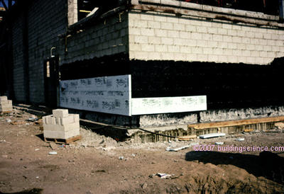
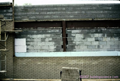
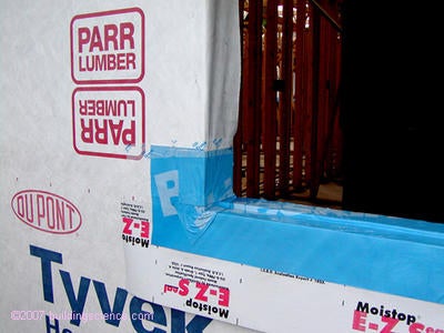
The most common drainage plane is “tar paper” or building paper (Photograph 1). More recently, the terms “housewrap” or “building wrap” have been introduced to describe building papers that are not asphalt impregnated felts or coated papers such as polyethylene or polypropylene films (Photograph 2). Drainage planes can also be created by sealing or layering water resistant sheathings such as a rigid insulation or coated structural sheathings (Photograph 3). Finally, fully adhered sheet membranes (Photograph 4), or trowel and spray applied coatings (Photograph 5) can act as drainage planes.
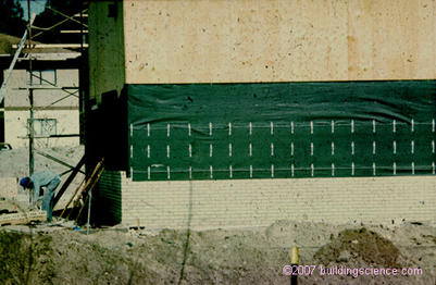
Photograph 1: Tar paper or building paper drainage plane
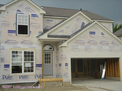
Photograph 2: “Housewrap” drainage plane
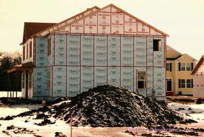
Photograph 3: Rigid foam insulating sheathing drainage plane
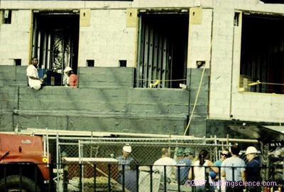
Photograph 4: Fully adhered sheet membrane drainage plane (and “air barrier” and “vapor barrier”)
Photograph 5: “Trowel-on” drainage plane
In commercial construction drainage planes are sometimes referred to as “air barriers,” but in my opinion are misnamed, as their principle fundamental function is rainwater control not air control. I prefer to refer to these type of commercial membranes as “drainage planes that also act as air barriers and vapor barriers” so that their primary function is emphasized. On drawings they should be referred to by their function – in order of importance. So if they also act as air barriers and vapor barriers they should be noted as such: e.g. “Membrane drainage plane/air barrier/vapor barrier.”
Drainage planes can be vapor permeable or vapor impermeable depending on climate, location within the building enclosure or required control function. Building papers and “housewraps” are typically vapor permeable (more than 10 perms) whereas fully adhered sheet membranes and trowel applied coatings are typically impermeable (less than 0.1 perms). There are a few recently developed spray and trowel applied coatings that are semi-vapor permeable (1 to 10 perms) that are likely to see wider application in the near future.
Fundamental Principle
The fundamental principle of rainwater control is to shed water by layering materials in such a way that water is directed downwards and outwards out of the building. The key to this fundamental principle is drainage.
Gravity is the driving force behind drainage. The “down” direction harnesses the force of gravity and the “out” direction gets the water away from the building enclosure assemblies, openings, components and materials. In general, the sooner water is directed out the better. Sooner, may not always be practical – such as at window openings where draining a window into a drainage space behind a cladding is often more practical than draining them to the exterior face of the cladding.
The most elegant expression of this concept is a flashing (Figure 1). Flashings are the most under-rated building enclosure component and arguably the most important. Flashings are integrated with drainage planes creating for all practical purposes a flashing for the entire assembly (Figure 2). A “screen” or “cladding” is installed over the drainage plane to provide aesthetics and to provide protection from ultra-violet radiation and mechanical damage (Figure 3). Drainage occurs between the cladding and the drainage plane.
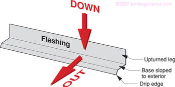
Figure 1: Flashing
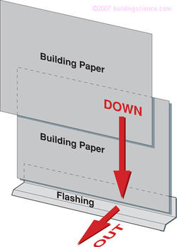
Figure 2: Flashing integrated with drainage plane – a “flashing for the entire assembly”
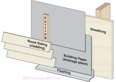
Figure 3: Cladding or “screen” installed over drainage plane with a
provision for both drainage and ventilation of cladding
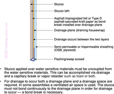
Figure 4: Stucco with a drainage plane and a drainage space
Drainage vs. Ventilation
In order for drainage to occur, a drainage space must be provided between the cladding and the drainage plane. The width of this space varies depending on cladding type and function. Sometimes the drainage space is also called upon to act as a “ventilation space.”
Effective drainage of rainwater can occur in drainage spaces as small as 1/16 to 1/8 inch (2 or 3 mm) (e.g. between two layers of building paper in a stucco cladding – Figure 4). However, effective ventilation may require spaces as large as 3/4 to 1 inch (20 to 25 mm) depending on the moisture load (e.g. between a brick veneer and a building wrap – Figure 5).
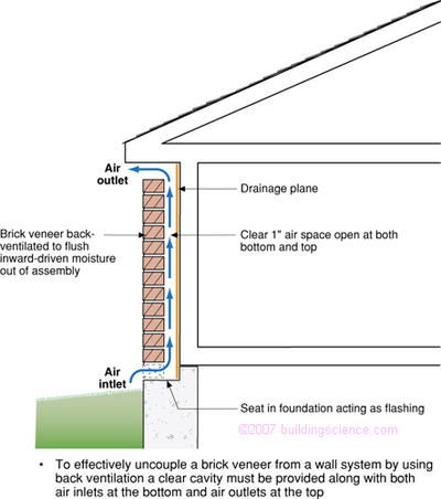
Figure 5: Brick veneer with a drainage plane, drainage space and ventilation space
Why ventilate a cladding in addition to providing drainage? Some claddings act as reservoirs – materials that store water. Once the reservoirs get wet, the stored water can migrate elsewhere and cause problems. The most common reservoir cladding is a brick veneer (although wood siding and stone also can be significant reservoir claddings. Serious problems can occur with rain wetted brick veneers and inward moisture movement due to solar radiation particularly where an interior vapor barrier is installed (Figure 6).
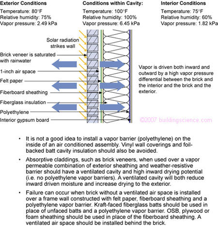
Figure 6: Inward movement due to solar radiation
“Back ventilating” a reservoir cladding uncouples or disconnects the reservoir cladding from the rest of the wall assembly. The greater the reservoir, the greater the moisture load, and the greater the ventilation required. A reservoir cladding can also be uncoupled by providing a condensing surface such as an impermeable insulating sheathing (Figure 7) or by using a fully adhered sheet membrane that is also impermeable (i.e. also a vapor barrier). This is a particularly attractive approach where it is not possible or practical to provide a cavity (“ventilation space”) free from mortar droppings.
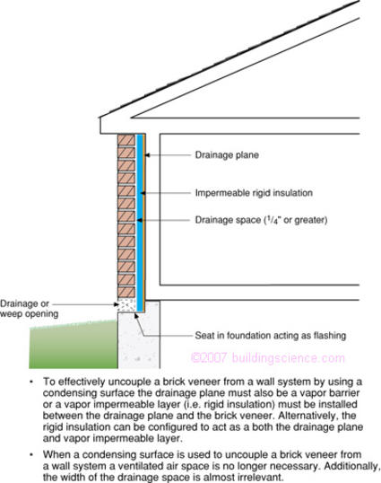
Figure 7: Brick veneer with a drainage plane, drainage space and condensing surface
With wood siding, the drainage space is typically intermittent and depends largely on the profile of the siding. Ideally, wood siding, should be installed over furring creating a drained (and vented) air space between the drainage plane and wood siding. With vinyl and aluminum siding, the drainage space is more pronounced and furring is not necessary.
With stucco claddings, the drainage space was traditionally provided by using two layers of asphalt impregnated felt paper. The water absorbed by the felt papers from the base coat of stucco caused the papers to swell and expand. When the assembly dried, the papers would shrink, wrinkle and de-bond from the stucco rendering providing a tortuous, but reasonably effective drainage space.
With brick veneers, the width of the drainage space has been based more on tradition than physics. A 1-inch (25 mm) airspace is more-or-less the width of a mason’s fingers, hence, the typical requirement for a 1-inch (25 mm) airspace. However, historical experience with stucco and other cladding systems show spaces as small as 1/16 inch (2 mm) drain. However large the space it must be coupled with a functional drainage plane.
Drain the Opening
Drainage planes should be integrated with windows and doors. Actually, they should be integrated with window and door openings rather than the windows and doors themselves.
The seal between a window or door component and the drainage plane” is rarely perfect – and even if it is perfect at the time of installation it certainly will not be perfect forever.
Furthermore, the window or door component within the opening is rarely perfect – it can and often does leak. This leakage should be managed in the same manner leakage is managed in the plane of the assembly - by drainage to the outside.
Window and door openings should be drained to the exterior using the same principles used in the design and construction of wall assemblies in general.
Pan flashings, membranes lining openings, precast sills with seats extending under window and door units, formable flashings, building papers, housewraps lining openings are all methods of providing drained openings (Photograph 7).
Photograph 6: Note absence of drainage plane – problem in the making
Photograph 7: Membrane lining window opening creating a “pan flashing”
These techniques allow for sealants to be installed imperfectly or for sealants to age without resulting in catastrophic failure of the assembly. A leak is not truly a leak if it leaks back to the exterior without wetting a water sensitive material.
Drain the Component
Windows and doors are components that are assembled from elements. Where elements join together at a joint a potential for water leakage exists. Ideally, elements should be designed and assembled in such a way that each element sheds water to the exterior and each joint connection between elements drains to the exterior.
Sealants and gaskets at joints should not be relied on to provide the only defense against water entry. The principle of drainage applies to the design and construction of window and door components in the same way that it applies to walls and openings.
Drain the Material
Water that is absorbed in a material can not be drained away. Assembly materials that are outboard of drainage planes should not absorb water or should be treated to shed water. Wood trim and wood siding should be coated on all surfaces to repel water. Think of this as a “capillary break” for the materials themselves (cladding and trim) that are outboard of the capillary break for the wall itself (typically the “drainage plane” or the “drainage plane” coupled with the “drainage space”).
The repelled water should be drained away. Ideally, these materials should also be “back-vented” so that absorbed water can evaporate and be vented to the exterior.
Claddings that are water absorptive such as stucco and brick should be separated from the rest of the assembly by a capillary break. This capillary break can be an airspace or a material that sheds water or does not absorb water or does not pass water.
Stuccos should be coated to reduce water absorption or mixed in proportions or with additives to reduce water absorption. Brick veneers should be “back-vented” using an air space that is open to the atmosphere at both the bottom of the wall and the top.
Window and door elements should also be treated to repel water or coated to repel water or manufactured from materials that do not absorb or transmit water. For wood windows this means that all wood pieces that comprise the window should be coated and treated on all six surfaces – with the most critical surfaces being the ends. End grain surfaces are the most prone to water absorption.
Drain the Building Enclosure
The drainage plane and drainage logic should encompass the entire building enclosure. Deck, balcony and railing connections should be designed and constructed to shed or drain water to the exterior. Roof-wall connections and roof dormer connections should be designed and constructed to shed or drain water to the exterior (Photograph 8). Garages, decks, and terraces should be sloped to the exterior and drained. And sites should be graded to shed or drain water away from building perimeters.
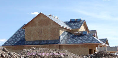
Photograph 8: Membrane connecting dormer drainage plane to roof drainage plane
Summary
Assemblies should be designed and constructed to shed or drain water to the exterior. The key component in this approach is a drainage plane. Window and door openings should be designed and constructed to shed or drain water to the exterior and be integrated with the drainage plane. Windows and doors should be designed and manufactured to shed or drain water to the exterior. Building materials should drain or be treated such that they drain rather than store water. Building connections should be designed and constructed to drain to the exterior.