Driving rain deposition is quantitatively the largest single source of moisture for most walls and roofs leading to building enclosure deterioration. Controlling rain penetration is, therefore, one of the most important parts of a successful moisture control strategy which involves understanding and predicting moisture movement within and through the enclosure to improve building enclosure performance, particularly durability. This document will consider rain control from a general to a specific level. The following sections will cover: basic moisture control principles that should be employed in the design of above-grade building enclosures; driving rain as a moisture load on walls; a classification system of the various rain control strategies available for walls; and finally, good design practices for walls.
Driving Rain
Driving rain is typically the largest source of moisture for the above-grade building enclosure. Hence, control of rain penetration and absorption is a fundamental function of the building enclosure, and a major part of its moisture control functions. Despite thousands of years of experience, avoiding rain-related building damage is still one of the most difficult tasks designers and builders face. There are, however, means of providing rain control which are based on both traditional details and modern physical understanding. Regardless of the wall design approach taken, building shape and site design choices can reduce the amount of rain deposited on walls. Finally, despite our best efforts, some rain often is absorbed into materials or penetrates through imperfections so drying must be provided to remove this incidental moisture.
This holistic state-of-the-art approach to rain control can be described by the three-D’s: Deflection, Drainage/Storage/Exclusion, and Drying. The next three sections of this digest will investigate each in turn.
1. Deflection
The climate and the site play a large role in defining the rain exposure that a building is exposed to. Most parts of the world experience a significant amount of wind-driven rain, and those areas exposed to typhoons can have extreme exposure conditions. While this type of climate demands good rain control strategies for enclosure walls, the rain deposited on walls can be significantly reduced by good design and siting.
The first line of defence is the siting of the home—exposure to the prevailing driving rains can be defended against by plantings, landscaping, and by choosing lower building designs (i.e., bungalows).
The shape of the roof and overhangs also have a critical impact. Field measurements [1] and computer modelling [2] have shown that overhangs and peaked roofs reduce rain deposition by approximately 50%. A damage survey of wood frame buildings in British Columbia [3] found that the size of a buildings overhang correlated directly with the probability of rain-related damage (Figure 1).
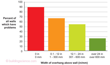
Figure 1: Wall problems as a function of the overhang size from a field survey.
Peaked roofs and overhangs protect a wall from rain by shadowing and redirecting airflow (Figure 2). Hipped roofs provide an opportunity to shelter the walls from rain on all four sides of the building and also increase the resistance to damage during high winds.
Field measurements [4,5,6,7], computer modelling [8,9], and wind tunnel testing [10] have provided an indication of the quantity of driving rain deposition that can be expected on vertical walls. For many low-rise buildings, the amount of rain deposited on the worst part of the building is in the order of 10 to 20% of the product of wind speed and rainfall intensity for each orientation. Thus the amount of rain deposited on the walls of houses erected on exposed sites could be in the order of tens to hundreds of litres per square meter per year (0.2 to 2 gallons per square foot per year). Sheltered locations and single-storey houses with wide overhangs will be exposed to much less than this amount of rain.
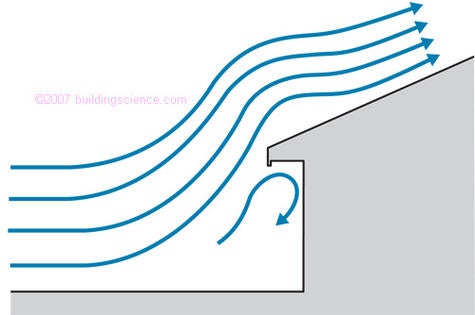
Figure 2: Influence of overhangs and pitched roofs on wind and rain flow.
Once water is on the wall it will form a film and begin flowing downward under the force of gravity. Wind flowing over the surface will tend to deflect the flow from this path and, in extreme cases, may even force water upward. Surface features such as trim, surface texture, and openings can greatly affect the flow paths of this surface drainage, either concentrating or dispersing surface flows.
Traditional surface details on old and vernacular buildings often served the function of directing water away from sensitive areas (e.g., windows) and distributed surface water in such a way as to prevent the concentrated streams which cause staining. The copious use of drip edges and slopes also ensured that surface water was shed from the building surface as often as possible.
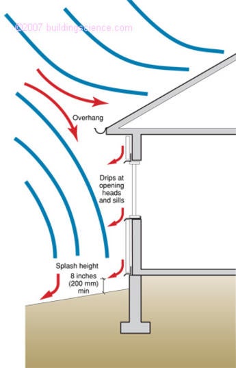
Figure 3: Principles of rain deflection.
2. Drainage/Storage/Exclusion
Siting, building shape, and surface rainwater control rarely provide complete rain control in rainy climates (although deep, wrap around porches may eliminate the need for rain control under them). Hence, some strategy to deal with the rainwater that penetrates the surface of the wall must be employed. There are three fundamental rain control strategies available to the designer [11]. In order of historical priority, they are:
- Storage (storage or mass walls),
- Exclusion (perfect barrier walls), and
- Drainage (drained and screened walls).
Categorization System
The categorization described is independent of materials or design intent and is based solely on the method by which a wall system controls rain penetration.
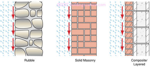
Figure 4: Examples of mass or storage wall systems.
Storage or mass walls are the oldest strategy. This approach requires the use of an assembly of materials with enough storage mass and moisture tolerance to absorb all rainwater that is not drained or otherwise removed from the outer surface. In a functional mass or storage wall this moisture is eventually removed by evaporative drying before it reaches the inner surface of the wall. Although enclosures employing this strategy might be best termed "moisture storage" systems, "mass" is often used because a large quantity of material is required to provide sufficient storage. The maximum quantity of rain that can be controlled is limited by the storage capacity available relative to drying conditions. Some examples of mass walls include adobe, solid multi-wythe brick masonry, and single-wythe block masonry.
Perfect barriers stop all water penetration at a single plane. Such perfect control required the advent of modern materials. Some examples of perfect barrier walls are some window frames, and some metal and glass curtain wall systems (Figure 5). Because it is difficult to build and maintain a perfect barrier wall, most walls are designed as, or perform as, imperfect barrier wall systems of either the mass type or the screened type. However, some systems, usually factory built, provide wall elements that are practical perfect barriers. The joints between perfect barrier elements may be also designed as perfect barriers (e.g. a single line of caulking). Such joints have a poor record of performance and should not be used to control rain entry.
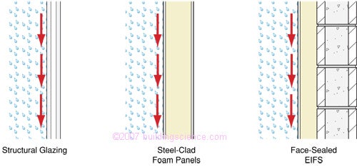
Figure 5: Examples of perfect barrier wall systems.
Screened-drained walls assume some rainwater will penetrate the outer surface (hence the cladding “screens” rain) and remove this water by designing an assembly that provides drainage within the wall. Since it has often been shown that lap siding and brick veneer leak significant amounts of water, this design approach is the most realistic and practical for such walls.
Some examples of drained wall systems include cavity walls, brick and stone veneer, vinyl siding, two-stage joints, and drained EIFS (Figure 6). It should be noted that the screen is much more than a rainscreen; it must also resist wind, snow, solar radiation, impact, flame spread, etc.
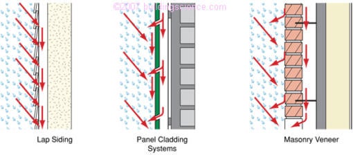
Figure 6: Examples of drained-screened wall systems.
In addition to drainage, supplementary functions, such as a capillary break or water barrier, should be employed to resist further inward movement of water that penetrates the inevitably imperfect cladding (see also BSD-105: Understanding Drainage Planes for more information on drained walls and drainage plane.)
All drained enclosure systems, whether walls, basements, or roofs, must have:
- a screen or cladding
- a drainage gap (often a clear air space),
- a drainage plane (a water repellent plane),
- flashing at the base to direct water outwards, and
- drain holes (weep holes) to allow water out of the drainage gap.
Water does not drain in the drainage gap like pressurized water in a pipe, but rather water flows down under the force of gravity clinging to a surface, e.g., the interface between the back of the cladding and the airspace or the interface between roofing paper and a roof shingle. It has been definitively shown in numerous lab and field studies that water can drain through very small gaps (in the order of the thickness of a dime), even the small gap between two sheets of building paper. However, even though the gap is small, a continuous drainage gap is required.
To act as a capillary break, the drainage gap should be in the order of 1/4” (6 mm) wide, since this is approximately the size of a gap that can be spanned by water. At this width the drainage gap has become a well-defined airspace. Since dimensional tolerances must be accounted for, a dimension of 3/8” (10 mm) is usually quoted for required minimum width of an airspace. This is based on the desire for a capillary break, not any technical need for drainage. A capillary break can also be provided by a hydrophobic material (such as a peel and stick for example).
An air space is often provided behind claddings to provide a ventilation space to ensure an uninterrupted drainage gap and act as a capillary break between the cladding and the remainder of the wall. This air space becomes more important as the rain loading increases since more water will drain within this space more often in high exposure locations. To allow for ventilation airflow (see the next section: Drying) the gap should be as unobstructed and large as possible. Small gaps (1/8” or 3 mm) can allow a small and potentially beneficial amount of ventilation flow, but larger gaps (over 3/8” or 10 mm) are usually required to ensure significant ventilation.
A vented airspace also allows for both some degree of pressure moderation. Pressure moderation is the term given to the mechanism whereby wind pressure differences across the cladding are reduced by connecting an air space behind the cladding with the wind-induced pressure acting on the exterior (Figure 7). By reducing air pressure differences across the cladding, rain will not be forced across openings by this force, while the standard features of capillary break, drainage, and flashing deal with the other rain penetration forces. If the air pressure is completely eliminated (not practical in the field [12,13,14]), the process is termed pressure equalisation.
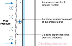
Figure 7: Pressure moderated air space.
Experience with buildings in most regions of North America [15, 16] has shown that drained and screened cladding systems are the preferred approach to reliably provide rain control. Drainage within the wall complements the shedding on the exterior surface.
Although drained-screened walls provide excellent rain penetration control, problems can still develop at interruptions in the plane of the wall. Windows, decks, and the termination of walls at grade all create interruptions in the drainage plane, gap and/or flashing and hence are locations where rain can penetrate. Flashing and drain holes must be provided at these penetrations to direct water in the drainage space to the exterior (Figure 8).
Joints between the wall and penetrating items or between joints within components (such as between the window frame and glazing) can use any one of the three strategies applied to walls (Figure 9). Joints are often designed as face-sealed perfect barrier elements made of sealant. These joints have a very high chance of failure, and may defeat the otherwise good performance of a drained or storage wall system. They are not recommended.
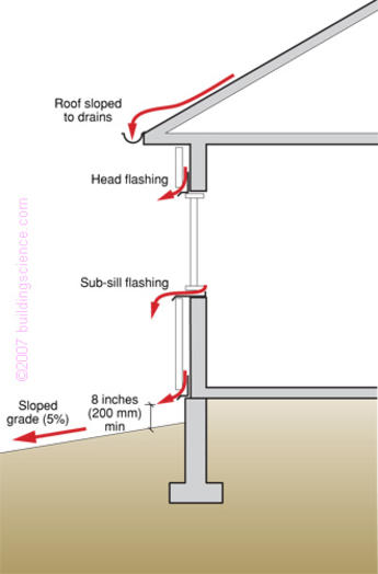
Figure 8: Drainage and flashing concepts.
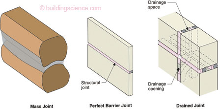
Figure 9: Three rain control strategies applied to joints.
Flashing must be made of a waterproof material (such as PVC, metal, or peel and stick membranes, not building paper or housewrap) since it is installed in a nearly horizontal manner [17]. Flashing must be installed in a continuous manner with an outward slope. Leaks often occur at lapped joints between lengths of rigid flashing, so these should be sealed, not just lapped.
Windows and especially mulled window joints and window corners often leak rainwater into the wall. To deal with this eventuality (some would say likelihood), sub-sill flashing should be installed. Essentially, the rough window should be prepared in such a way as to make it water resistant. The head of window should also be protected with flashing that directs surface rainwater away from the window and the window opening. This flashing directs water on the surface of the cladding and in the drainage gap safely outward. Head flashing and window sills should extend past the window jambs by at least 2” (50 mm) so that water flowing laterally on the flashing does not concentrate at the jamb but is directed away and dripped clear of the face of the cladding.
3. Drying
Despite all attempts to resist and drain water, field experience has shown that some water may still penetrate or be built in during construction. Drying of this moisture must be provided for.
Moisture can be removed from a wood framed wall clad with drained siding by (Figure 8):
- evaporation from the inside or outside surfaces,
- vapour transport by diffusion, air leakage, or both, either outward or inward;
- drainage, driven by gravity, and
- ventilation, if provided for.
Drainage is capable of removing the greatest volume of water in the shortest period of time. Hence, as described above, it is a very important mechanism for moisture control. Provided a clear drainage path exists (e.g. cavities, slopes, drainage openings), a large proportion of rainwater that penetrates the cladding can flow out of a wall.
A small but significant amount of water will usually remain attached to surfaces by surface tension and absorbed into materials by capillary forces even in walls with excellent drainage. Sidings of wood, fibercement, and masonry will also absorb and store moisture. This moisture can only be removed from a wall system by either diffusion or airflow.
Diffusive drying of water that is not removed by drainage can dry in either direction, depending on the wall system and the climate. In colder climates the vapor flow is often outwards, and inward drying only occurs during warm weather or when the sun shines on a wall. In warmer climates drying will often be to the interior.
If absorbent cladding materials or retained water in the drainage space is heated by direct solar exposure, the temperature rises well above the outdoor air temperature. This generates very large inward water vapour drives (which accelerate drying of the cladding), even in predominately heating climates. These inward drives can cause dangerous summertime condensation within wood framed walls, especially if a low-permeance vapor barrier (e.g., polyethylene) or finish (e.g. vinyl wall paper, mirrors, and cabinets) are used on the interior [20,21,22]. Additional control is often required to control inward vapor drives, and an outer layer with moderate or low vapor permeance (such as foam sheathings or thin-profile structural sheathing) is recommended.
Hence, in very cold climates, a vapour barrier of polyethylene sheet or aluminum foil may be acceptable. However, if absorbent cladding is used, a Class III vapor retarder combined with exterior insulating sheathing may be required to provide sufficient vapour diffusion control in cold weather while still allowing vapour to flow inward during warm weather.
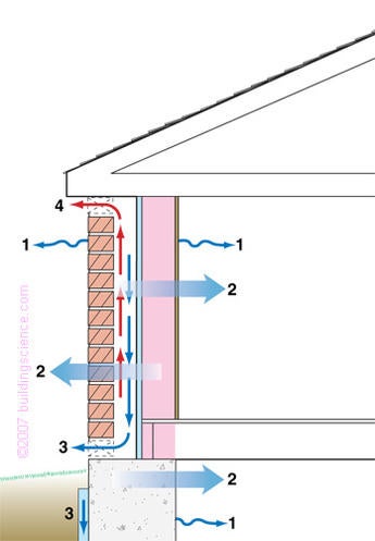
Figure 10: Moisture removal mechanism in drained and screened walls.
In mixed and hot-humid climates, (e.g., Houston, Atlanta, Knoxville) a vapor barrier on the interior should not be used, and only latex paint on drywall will allow sufficient vapor to pass through to the interior. With few exceptions, any material with low permeance (e.g., oil paint, aluminum foil, vinyl wallpaper, epoxy) must be avoided on the interior.
Air movement (or leakage) through the enclosure can, under the proper conditions, move a large quantity of moisture. While both cold weather air leakage outward and warm weather air leakage inward can cause condensation and hence wetting, the opposite conditions (e.g. inward flow in cold weather) will provide some drying. In some cases, this drying can be significant. Because air leakage through the enclosure is difficult to control, expensive in terms of energy, and potentially dangerous for indoor air quality, the modern approach is to limit airflow through the wall to nearly zero. This also eliminates the potential for airflow drying, so drying must be secured by other means.
Ventilation, or exterior airflow behind the cladding driven by wind pressure differences on the face of the building or solar heated air rising, is useful since it accelerates drying. Ventilation bypasses the high vapour resistance of claddings such as vinyl siding, metal panels, and cement board, thereby allowing outward drying. A recent study [18] and previous European research [19] has confirmed that ventilation drying occurs. This research shows that a clear space should be provided behind cladding to encourage ventilation, and that clear vents must be placed at the top and bottom for the most effective ventilation. Lapped siding with joints unsealed by thick paint layers tends to act as if it were ventilated.
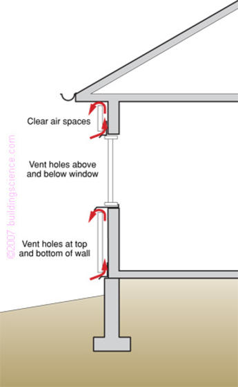
Figure 11: Ventilation concepts.
Ventilation is also important since it can reduce or control solar-driven inward vapor drives, by safely redirecting the vapor to the exterior even in hot-humid conditions [23].
Recommendations for Practice
Moisture control in above-grade walls is best achieved by the proper selection of materials and design of assemblies so that both storage and a drying potential higher than the wetting potential are provided. Because of the magnitude of driving rain deposition, rain control should be an important part of a moisture control strategy for the above-grade building enclosure. A designer must have a well-conceived strategy for rain control for each enclosure type, and joint type, for the entire project.
Regardless of which strategy or assembly is considered, reducing the amount of rain deposited (i.e., controlling exposure by the judicious choice of site and building shape) and increasing the fraction shed from the exterior face will reduce the moisture load on the assembly. Controlling water by the use of generous overhangs, proper window sills, and other surface drainage features should almost always be the first and most important step in designing for the control of rainwater penetration.
Storage Systems
Storage (sometimes called mass or reservoir systems) walls are often used in low-rise commercial buildings (in the form of single-wythe concrete block), and some high-rise residential buildings (in the form of exposed concrete shear walls). Provided the absorbency and safe storage capacity are well matched to the local exposure and climatic conditions, storage walls may be a reasonable choice. Deflect as much rain from the building as possible with good details, and beware warm weather inward vapour diffusion.
Mass walls are sometimes prohibitively expensive (in materials, structural weight, or floor space). Failure of joints (designed as perfect barriers) between wall elements, or the interface with windows, doors, balconies, etc. is often the cause of rain penetration, even when the wall element itself is functional. If a sufficient amount of storage is provided for the exposure conditions and absorbency of the material, performance of a mass wall system will depend on the performance of joints and interfaces.
Perfect Barrier Systems
Perfect barrier systems, especially face-sealed versions, often fail to perform as designed, if not initially, then after many years of exposure. The perfect barrier systems that appear to function in the field usually lend their performance to the fact that other layers are providing drainage and/or storage: in effect these "perfect barrier systems" are acting as screened systems or mass systems. Perfect barrier wall elements built with tight quality control in factory conditions and connected in the field with drained-screened types of joints may be able to provide good performance for a long service life. In almost all cases, drained systems with the same amount of material and labor will provide better, longer-lasting rain control.
If you must use a perfectly sealed system, pay extra attention to surface drainage, joints, and buildable details. Quality control is essential on site, and maintenance important. Use these systems under low exposure conditions, and/or in situations in which a rain leak will not be catastrophic (e.g., there are no moisture sensitive materials). Consider a redundant backup system to deal with the possibility of local failures.
Concealed barrier approaches tend to have better performance than face sealed systems (as the key components are less exposed to temperature and radiation extremes). This is especially true for roofs: the membranes in inverted roofs have much longer life than exposed membrane face sealed roofs.
Drained-Screened Systems
Screened wall systems are inherently more forgiving than either mass or perfect barrier systems. Properly designed and built screened wall systems will provide economical and durable rain penetration control. Failures in screened systems tend to occur because drainage was not provided (either through a design or construction failure). So long as sufficient drainage is provided, the combination of the number of layers, their absorbencies, and their penetration fraction will define a screened systems’ ability to control rainwater.
The most reliable and widely applicable approach is to follow the mantra: “Deflection, Drainage/Exclusion/Storage, and Drying”. The use of perfect barriers and storage systems can be successful if properly applied.
Proper siting of the building and the use of sloped hip roofs and generous overhangs deflect driving rain, even for tall buildings. Water on the surface of the wall is shed from and deflected around openings by surface features, drip edges, and protruding flashing. Water is removed from the base of the wall by sloping the grade, and siding is kept at least 8” (200 mm) above grade to protect it from splashes.
Rainwater will penetrate the cladding at joints, laps and penetrations. This water should be removed by drainage through a drainage space and redirected to the exterior by the use of waterproof flashing with all lap joints sealed.
Water will remain within the drainage cavity, will be absorbed into the cladding, and may even penetrate into the structural sheathing or stud space. This water should be removed by drying to the exterior and the interior by allowing diffusion drying and ventilating the space behind the cladding.
Pressure equalized screened systems offer only marginal benefits in most situations. So long as drainage and capillary breaks are provided, the reduced water penetration that may (and in many cases may not) result from pressure equalization does not aid rain control—failure will still be by a failure to drain.
References
[1] Straube, J.F., Moisture Control and Enclosure Wall Systems. Ph.D. Thesis, Civil Engineering Department, University of Waterloo, April, 1998.
[2] Blocken, B., Carmeliet, J., “Driving Rain on Building Envelopes—I. Numerical Estimation and Full-Scale Experimental Verification", J. of Thermal Insulation and Bldg Envelopes, Vol 24, No 4, 2000, pp. 61-110.
[3] Survey of Building Envelope Failures in the Coastal Climate of BC. Report by Morrison-Hershfield for CMHC, Ottawa, Nov. 1996.
[4] Lacy, R.E., Driving-Rain Maps and the Onslaught of Rain on Buildings. Building Research Station Current Paper 54, HMSO Garston, U.K., 1965.
[5] Straube, J.F., and Burnett, E.F.P.,"Driving Rain and Masonry Veneer", Water Leakage Through Building Facades, ASTM STP 1314, R. Kudder and J.L. Erdly, Eds., American Society for Testing and Materials, Philadelphia, 1997, pp. 73-87.
[6] Künzel, H.M., Regendaten für Berechnung des Feuchtetransports, Fraunhofer Institut für Bauphysik, Mitteilung 265, 1994.
[7] Frank, W. Entwicklung von Regen and Wind auf Gebaeudefassaden, Verlag Ernst & Sohn, Bertichte aus der Bauforschung, 1973, Vol 86, pp. 17-40.
[8] Choi, E.C.C., "Determination of the wind-driven-rain intensity on building faces", J. of Wind Engineering and Industrial Aerodynamics, Vol 51, 1994, pp. 55-69.
[9] Karagiozis, A., and Hadjisophocieous, G., "Wind-Driven Rain on High-Rise Buildings", Proceedings of BETEC/ASHRAE/DOE Thermal Performance of Building Envelopes VI, Dec., 1995, pp. 399-406.
[10] Inculet, D.R., Surry, D., "Simulation of Wind-Driven Rain and Wetting Patterns on Buildings," Report BLWT-SS30-1994, U. of West. Ontario, London, Nov, 1994.
[11] Straube, J.F. and Burnett, E.F.P., "Rain Control and Design Strategies". J. Of Thermal Insulation and Building Envelopes, July 1999, pp. 41-56
[12] Quirouette, R., Laboratory Investigation and Field Monitoring of Pressure-Equalized Rainscreen Walls, CMHC Research Report, September, 1996.
[13] Inculet, D., Surry, D., The Influence of Unsteady Pressure Gradients on Compartmentalization Requirements for Pressure-Equalized Rainscreens, CMHC Research Report by the Boundary Layer Wind Tunnel, University of Western Ontario, June, 1996.
[14] Laviolette, S., and Keller, H., Performance Monitoring of a Brick Veneer / Steel Stud Wall System, CMHC Research Report by Keller Engineering, June, 1993.
[15] Rain Control Report by CMHC
[16] Lstiburek, J., Builders Guide for Cold Climates, Building Science Press, Westford, MA, 2005.
[17] Best Practise Guide for Flashing, Canada Mortgage and Housing Corporation, Ottawa.
[18] Straube, J.F. Burnett, E.F.P., Vents, Ventilation Drying, and Pressure Moderation. University Of Waterloo Building Engineering Group report for CMHC, Ottawa, 1995.
[19] Popp, W., Mayer, E., Künzel, H., 1980. Untersuchungen über die Belüftung des Luftraumes hinter vorgesetzten Fassadenbekleidung aus kleinformatigen Elementen. Forschungsbericht B Ho 22/80: Fraunhofer Institut für Bauphysik, , Holzkirchen, Germany.
[20] Wilson, A.G., "Condensation in Insulated Masonry Walls in the Summer", Proc. Of RILEM/CIB Symposium, Helsinki, 1965, pp. 2-7.
[21] Sandin, K., 1991. Skalmurskonstruktionens fukt- och temperaturbetingelser. Rapport R43:1991 Byggforskningsrådet, Stockholm, Sweden.
[22] Andersen, N.E.,"Summer Condensation in an Unheated Building", Proc. of Symposium and Day of Building Physics, Lund University, August 24-27, 1987, Swedish Council for Building Research, 1988, pp. 164-165.
[23] Straube, J.F. and Burnett, E.F.P., "Drainage, Ventilation Drying, and Enclosure Performance", Proceedings of Thermal Performance of Building EnvelopesVII, Clearwater Beach Florida, December 4-7, 1998, pp 189-198.