Moisture accumulates when the rate of moisture entry into an assembly exceeds the rate of moisture removal. When moisture accumulation exceeds the ability of the assembly materials to store the moisture without significantly degrading performance or long-term service life, moisture problems result.
Various strategies can be implemented to minimize the risk of moisture damage. The strategies fall into the following three groups:
- control of moisture entry
- control of moisture accumulation
- removal of moisture
Strategies in the three groupings can be utilized in combination and have been proven to be most effective in that manner. Strategies effective in the control of moisture entry, however, are often not effective if building assemblies start out wet and, in fact, can be detrimental. If a technique is effective at preventing moisture from entering an assembly, it is also likely to be effective at preventing moisture from leaving an assembly. Conversely, a technique effective at removing moisture may also allow moisture to enter. Balance between entry and removal is the key in many assemblies.
Of the mechanisms involved in the surface wetting and interstitial wetting of building assemblies, the most significant is liquid flow where rain and groundwater are the moisture sources. Controlling rain entry above grade and groundwater entry below grade have traditionally been the preoccupation of generations of builders and designers. Air transport and vapor diffusion are not so obvious contributions to the wetting of building assemblies. Each mechanism is capable of leading to moisture-related building problems.
All moisture movement and therefore any moisture-related problem is a result of one of these mechanisms or some combination of these mechanisms.
Historically, successful approaches to moisture control have typically been based on the following strategy: (1) prevent building assemblies and surfaces from getting wet from the exterior, (2) prevent building assemblies and surfaces from getting wet from the interior, and (3) should building assemblies or surfaces get wet, or start out wet, allow them to dry to either the exterior or the interior.
Building assemblies in all climates can get wet from the exterior in similar manner by liquid flow (rain and groundwater as moisture sources). Accordingly, techniques for the control of liquid flow are similar in all climates and are interchangeable.
However, building assemblies get wet by air movement and vapor diffusion in a different manner depending on climate and time of year. Accordingly, techniques for the control of air movement and vapor diffusion can be different based on climate and may not be interchangeable.
The “duality” that air movement and vapor diffusion possess with respect to their ability to move moisture from both the interior and exterior into the building enclosure is dependent on both climatic and interior conditions and is often overlooked by designers and builders. It is not unusual to find “cold” climate building enclosure designs employed in “warm” climate regions. Even more confusing to the builder and designer are conditions where both heating and cooling occur for extended periods of time.
Climate Dependence of Moisture Control
Buildings should be suited to their environment, both exterior and interior. It is not typically practical to construct the same manner of building in Montreal, Memphis, Mojave and Miami. It is cold in Montreal, it is humid in Memphis, it is hot and dry in Mojave and it is hot and wet in Miami. And that is just the outside environment. It is also not desirable to construct the same manner of building to enclose a garage, house, and swimming pool. The interior environment also clearly influences design of the building enclosure and mechanical system.
Environmental Loads
Hygro-thermal regions and rain exposure zones are defined as environmental loads [1]. These loads should be used in the design, construction, operation, diagnosis and understanding of building enclosures and mechanical systems (see Sidebar). The mantra “location, location and location” applies not just to real estate but also to building science.
Surface Mold and Other Biological Growth
The following conditions are necessary and sufficient for mold and other biological growth to occur on surfaces:
- mold spores must be present
- a nutrient base must be available (most surfaces contain nutrients)
- temperature range between 40 (4.4°C) and 100°F (37.7°C)
- relative humidity adjacent to surface above 70% [2]
Of these conditions, relative humidity near surfaces is the most practical to control. Spores are always present in outdoor and indoor air. Almost all of the commonly used construction materials can support mold growth; therefore, control of available nutrients is limited and human comfort constraints limit the use of temperature control.
Where relative humidities near surfaces are maintained below 70%, mold and and other biological growth can be controlled. Since relative humidities are dependent on both temperature and vapor pressure, mold control is dependent on controlling both the temperature and vapor pressure near surfaces.
In cold and very cold climates, mold growth on interior surfaces occurs during the heating season because the interior surfaces of exterior walls are cool from heat loss and because moisture levels within the conditioned space are too high. Mold growth control is facilitated by preventing the interior surfaces of exterior wall and other building assemblies from becoming too cold and by limiting interior moisture levels. The key is to prevent relative humidities of adjacent surfaces from rising above 70%. The thermal resistance of the building enclosure and the local climate determine the interior surface temperatures of exterior walls and other building assemblies. Controlled ventilation and source control limit the interior moisture levels.
Experience has shown that where interior moisture levels in cold climates during the heating season are limited to the 25 to 30% relative humidity range at 70°F (21.1°C), relative humidities adjacent to the interior surfaces of exterior walls (of typical thermal resistance) fall below 70% and mold growth is controlled. The colder the climate (for the thermal resistance of any given building enclosure), the lower the interior relative humidity necessary to prevent 70% relative humidities from occurring adjacent to interior surfaces of exterior walls. Building enclosures of similar thermal resistance (building code minimums) located in Minneapolis, Minnesota and Cincinnati, Ohio should be limited to different interior moisture levels during the heating season. A 25% interior relative humidity at 70°F (21.1°C) would be appropriate for Minneapolis. Interior relative humidities up to 30% at 70°F (21.1°C) would be appropriate for Cincinnati. Correspondingly, the higher the desired interior relative humidity, the higher the thermal resistance necessary to control relative humidities adjacent to interior surfaces.
In mixed climates, during the heating season, interior moisture levels should be limited to the 30 to 40% relative humidity range at 70°F (21.1°C). This limits the relative humidity adjacent to the interior surface of exterior walls to below 70% for the typical thermal resistance found in most building assemblies in these climate zones.
In hot-humid climates, interior mold growth also occurs because interior surfaces are typically cold and subsequently accessed by moisture levels which are too high. The cold surfaces in cooling climates arise from the air conditioning of enclosures. When exterior hot air is cooled, its relative humidity increases. If the exterior hot air is also humid, cooling this air will typically raise its relative humidity above the point at which mold growth can occur (70%).
Where air-conditioned “cold” air is supplied to a room, and this air is “blown” against an interior surface due to poor diffuser design, diffuser location, or diffuser performance, cold spots can occur on the interior gypsum board surfaces. Although this cold air is typically dehumidified before it is supplied to the conditioned space, it can create a mold problem on room surfaces as a result of high levels of airborne moisture within the room contacting the cooled surface. This typically leads to a rise in relative humidity near the surface and a corresponding mold problem.
If exterior humid air comes in contact with the interstitial cavity side of cooled interior gypsum board, mold and other biological growth can occur. Cooling this exterior hot, humid air by air conditioning or contact with cool surfaces will raise its relative humidity above 70%. When nutrients are present, mold and other growth occurs. This is exacerbated with the use of impermeable wall coverings such as vinyl wallpaper, which can trap moisture between the interior finish and the gypsum board. When these interior finishes are coupled with cold spots (from poor diffuser placement and/or overcooling) and exterior moisture, mold and other growth can occur.
Accordingly, one of the most practical solutions in controlling mold and other biological growth in hot-humid climates is limiting hot, humid exterior air or other forms of moisture transport from contacting the interior cold (air-conditioned) gypsum board surfaces (controlling the vapor pressure at the surface). This is most commonly facilitated by maintaining the conditioned space at a slight positive air pressure to the exterior (approximately 2 to 3 Pa). Pressurization of building enclosures is expedited by airtight construction (2.00 l/(s-m2)@75 Pa) [3].
In hot-humid climates interior moisture levels within the conditioned space should also be limited to 60% relative humidity at 75°F (23.8°C) by dehumidification, air conditioning and source control to prevent mold growth on the interior surfaces within the conditioned space.
Experience has also shown that where conditions for mold growth are controlled, other biological growth such as dust mite infestations can also be controlled. Specifically, for dust mites to grow, 70% relative humidities are also necessary. Carpets located on cold surfaces, such as concrete slabs, are particularly sensitive to dust mite growth. Carpets on cold surfaces should be avoided, or these surface temperatures should be elevated by the use of appropriate thermal insulation [5].
General Moisture Control Practices for all Climates
Building assemblies need to be protected from wetting via rainwater, groundwater, air transport and vapor diffusion. The typical strategies use drainage planes, air barriers, air pressure control, vapor retarders and control of interior moisture levels through ventilation and dehumidification. Climate location and season determine the location of air barriers and vapor retarders, pressurization versus depressurization, and ventilation versus dehumidification.
Moisture usually moves from warm to cold (driven by the thermal gradient) and from more to less (driven by the concentration gradient). In cold climates, moisture from the interior flows towards the exterior by passing through the building enclosure. In hot climates, moisture from the exterior flows towards the cooled interior by passing through the building enclosure.
The most important sources of moisture requiring control are:
- rainwater
- groundwater
- air transport
- vapor diffusion
Rainwater
The fundamental principle of rainwater control is to shed water by layering materials in such a way that water is directed downwards and outwards from the building or away from the building. It applies to assemblies such as walls, roofs and foundations, as well as to the components that can be found in walls, roofs and foundations such as windows, doors and skylights. It also applies to assemblies that connect to walls, roofs and foundations such as balconies, decks, railings and dormers.
Layering materials to shed water applies to the building as a whole. Overhangs can be used to keep water away from walls. Canopies can be used to keep water away from windows, and site grading can be used to keep water away from foundation perimeters.
Drainage is the key to rainwater control:
- drain the site
- drain the ground
- drain the building
- drain the assembly
- drain the opening
- drain the component
- drain the material
All exterior claddings pass some rainwater. Siding leaks, brick leaks, stucco leaks, stone leaks, etc. As such some control of this penetrating rainwater is required. In most walls this penetrating rainwater is controlled by a drainage plane that directs the penetrating rainwater downwards and outwards.
Drainage planes are water repellent materials (building paper, house wrap, foam insulation, etc), which are located behind the cladding and are designed and constructed to drain water that passes through the cladding. They are interconnected with flashings, window and door openings, and other penetrations of the building enclosure to provide drainage of water to the exterior of the building. The materials that form the drainage plane overlap each other shingle fashion or are sealed so that water flow is down and out of the wall.
Reservoir claddings on the exterior of buildings can be a problem. Reservoir claddings are materials that can store rainwater—sponges that get wet when it rains. Once the reservoirs get wet, the stored water can migrate elsewhere and cause problems. Common reservoirs are brick veneers, stuccos, wood siding, wood trim and fiber cement cladding.
Reservoir claddings should be uncoupled from the building. Back priming (painting all surfaces, back, front, edges and ends of wood siding, cement siding and all wood trim) are techniques that can limit the moisture storage issue with these materials.
Back venting brick veneers and installing them over foam sheathings also disconnects or uncouples the brick veneer moisture reservoir from the building. Installing stucco over two layers of building paper or over an appropriate capillary break such foam sheathing similarly addresses stucco reservoirs.
To state an obvious fact: we build outside. And often it rains when we are building outside. This means that walls without roofs on them will get wet. It is not a good idea to build these walls with exterior gypsum board that is paper faced. This is a major concern with party walls or firewalls in multifamily buildings. Glass faced gypsum board or other alternatives should be used.
Groundwater
The fundamental principles of ground water control are to keep rainwater away from the foundation wall perimeter and to drain groundwater with sub-grade perimeter drains before it gets to the foundation wall. This applies to slabs, crawlspaces and basements regardless of whether they are newly constructed or undergoing rehabilitation.
Concrete and masonry are sponges – they can wick water due to capillarity. This is the main reason that damp proofing (the black tar-like coating) is applied to exterior basement walls. The damp proofing fills in the pores in the concrete and masonry to reduce ground water absorption. The damp proofing is a capillary break. Under concrete floor slabs, the stone layer combined with polyethylene serves a similar function (they act as capillary breaks). Unfortunately, the capillary rise through footings is typically ignored. This can be a major problem if foundation perimeter wall are finished or insulated.
In new construction a capillary break should be installed on the top of the footing between the footing and the perimeter foundation wall. This can be done by damp-proofing the top of the footing or by installing a membrane at this location.
In new construction the interior insulation and finishing approach must take into account the moisture migrating up through the footing. This is best accomplished by installing vapor semi-permeable rigid foam insulation on the interior of the assembly to protect the interior finishes and to release the capillary water to the interior in a controlled manner – at a rate that does not damage interior finishes or lead to mold.
The best foams to use have a perm rating of greater than 1 perm for the thickness used. This means limiting extruded polystyrene insulation to less than 1-inch thickness for walls (more than 1 inch thick and they do not breathe sufficiently) and making sure that the rigid insulation is not faced with polypropylene skins or foil facings. Additionally, since foams need to be protected from fire, and this is often done with gypsum board only latex paint should be used on interior gypsum finishes (since it breathes).
Capillary control also applies to slab-on-grade construction and crawlspaces. Monolithic slabs need plastic ground covers that extend under the perimeter grade beam and upwards to grade. Additionally, the exposed portion of slabs should be painted with latex paint to reduce water absorption and a capillary break should be installed under perimeter wall framing.
Air Transport
The fundamental principle of ground air transported moisture is the use of an air barrier. Air barriers are systems of materials designed and constructed to control airflow between a conditioned space and an unconditioned space. The air barrier system is the primary air enclosure boundary that separates indoor (conditioned) air and outdoor (unconditioned) air. In multi-unit/townhouse/apartment construction the air barrier system also separates the conditioned air from any given unit and adjacent units. Air barrier systems also typically define the location of the pressure boundary of the building enclosure.
In multi-unit/townhouse/apartment construction the air barrier system is also the fire barrier and smoke barrier in inter-unit separations. The inter-unit separation must also meet the specific fire resistance rating requirement for the given separation.
The air barrier system also separates garages from conditioned spaces. In this regard the air barrier system is also the “gas barrier” and provides the gas-tight separation between a garage and the remainder of the house or building.
Air barriers are intended to resist the air pressure differences that act on them. Rigid materials such as gypsum board, exterior sheathing materials like plywood or OSB, and supported flexible barriers are typically effective air barrier systems if joints and seams are sealed. Spray foam systems can also act as effective air barrier systems either externally applied over structural elements or internally applied within cavity systems.
Air barrier systems keep outside air out of the building enclosure or inside air out of the building enclosure depending on climate or configuration. Sometimes, air barrier systems do both.
Air barrier systems can be located anywhere in the building enclosure—at the exterior surface, the interior surface, or at any location in between. In cold climates, interior air barrier systems control the exfiltration of interior, often moisture-laden air. Whereas exterior air barrier systems control the infiltration of exterior air and prevent wind-washing through cavity insulation systems.
Air barrier systems typically are assembled from materials incorporated in assemblies that are interconnected to create enclosures. Each of these three elements has measurable resistance to airflow. The recommended minimum resistances or air permeances for the three components are listed as follows [3]:
- Material 0.02 l/(s-m2)@75 Pa
- Assembly 0.20 l/(s-m2)@75 Pa
- Enclosure 2.00 l/(s-m2)@75 Pa
Materials and assemblies that meet these performance requirements are said to be air barrier materials and air barrier assemblies. Air barrier materials incorporated in air barrier assemblies that in turn are interconnected to create enclosures are called air barrier systems.
Materials and assemblies that do not meet these performance requirements, but are nevertheless designed and constructed to control airflow are said to be air retarders.
Vapor Diffusion
The fundamental principle of control of water in the vapor form is to keep it out and to let it out if it gets in. It gets complicated because sometimes the best strategies to keep water vapor out also trap water vapor in. This can be a real problem if the assemblies start out wet because of rain or the use of wet materials.
It gets even more complicated because of climate. In general water vapor moves from the warm side of building assemblies to the cold side of building assemblies. Logically, this means we need different strategies for different climates. We also have to take into account differences between summer and winter.
A vapor retarder is defined as follows:
Vapor Retarder*: The element that is designed and installed in an assembly to retard the movement of water by vapor diffusion.
The unit of measurement typically used in characterizing the water vapor permeance of materials is the “perm.” Several classes of vapor retarders are further defined as follows [4]:
Class I Vapor Retarder: 0.1 perm or less
Class II Vapor Retarder: 1.0 perm or less and greater than 0.1 perm
Class III Vapor Retarder: 10 perm or less and greater than 1.0 perm
Test Procedure for vapor retarders: ASTM E-96 Test Method A (the desiccant method or dry cup method)
Finally, a vapor barrier is defined as:
- Vapor Barrier: A Class I vapor retarder.
Materials can be separated into four general classes based on their permeance [4]:
Vapor impermeable: 0.1 perm or less
Vapor semi-impermeable: 1.0 perm or less and greater than 0.1 perm
Vapor semi-permeable: 10 perms or less and greater than 1.0 perm
Vapor permeable: greater than 10 perms
Based on the definitions the following general principles should be followed in assembly design:
Avoidance of using vapor barriers where vapor retarders will provide satisfactory performance. Avoidance of using vapor retarders where vapor permeable materials will provide satisfactory performance. Thereby encouraging drying mechanisms over wetting prevention mechanisms.
Avoidance of the installation of vapor barriers on both sides of assemblies—i.e. “double vapor barriers” in order to facilitate assembly drying in at least one direction.
Avoidance of the installation of vapor barriers such as polyethylene vapor barriers, foil-faced batt insulation and reflective radiant barrier foil insulation on the interior of air-conditioned assemblies—a practice that has been linked with moldy buildings.
Avoidance of the installation of vinyl wall coverings on the inside of air-conditioned assemblies.
Moisture Control Practices for Cold Climates
A cold climate has 5,400 heating degree days or greater and a very cold climate has 9,000 heating degree days or greater. Intermittent cooling (air conditioning) typically occur in cold climates but is uncommon in most very cold climates. The climate zone specifications are broad and general for simplicity. Specific microclimates should always be considered. Incident solar radiation, nearby water and wetlands, and vegetation and undergrowth all affect the microclimate of a building assembly. For any specific location, designers and builders should consult weather records and consider local experience.
Key Concerns and Control Strategies
In cold climates, the principal moisture concerns are rain penetration, groundwater, interstitial condensation (condensation within building assemblies), and interior mold and mildew linked to high interior levels of humidity.
Typically, in cold climates, wetting from the interior during the heating season by air movement is a major concern. In cold climates, building enclosures are constructed in an airtight manner to control air leakage openings and to facilitate controlled ventilation, which provides for the dilution of interior pollutants and interior moisture by controlled air change.
Vapor diffusion from the interior can be a concern in cold climates and is typically a concern in very cold climates. Vapor diffusion retarders, when specified in cold climates and very cold climates, are located towards the interior of the thermal insulation. When vapor retarders are used, walls and other building assemblies are designed and built to dry to the exterior, should they get wet or start out wet.
The presence of ground frost penetration concerns in these climates has led to the widespread use of basement foundations, with foundation footings located below ground frost penetration depth. Frost-protected crawlspaces are common in the more moderate regions of cold climates. Concrete and masonry foundations are common with limited use of wood foundations. Above-grade frame walls predominate.
Condensation Within Building Assemblies
Conditioned spaces are heated by both electric and fuel-fired appliances. Traditional negative interior air pressures have been reduced as a result of the trend away from active chimneys toward high-efficiency combustion appliances and electric heat sources. When combined with the trend towards tighter enclosures, reduced airchange, and higher levels of interior moisture, this has led to concerns about the exfiltration of interior moisture-laden air leading to condensation within insulated assemblies. Reduced air change and resultant higher levels of interior moisture have led to elevated incidences of interior surface mold and mildew.
Air leakage from the interior into insulated attics during the heating months, coupled with insufficient attic ventilation, can lead to roof sheathing decay. Air leakage into insulated wall cavities during the heating months, coupled with an insufficient or limited drying ability, can lead to the decay of structural framing members.
Moisture movement by air leakage (the exfiltration of interior moisture-laden air) is controlled in several ways. Air leakage openings can be limited, sheathing temperatures can be controlled via the use of insulating sheathings, and the interior moisture levels can be controlled by ventilation (dilution by air change) combined with source control. Source control involves direct venting of clothes dryers, as well as the use of subgrade vapor retarders under concrete floor slabs and bath and kitchen exhaust systems.
Moisture movement by vapor diffusion from the interior can controlled by the use of vapor diffusion retarders in walls, roofs, and foundations or can be managed by controlling sheathing temperatures via the use of insulating sheathings.
Cladding systems which can absorb significant amounts of moisture when exposed to rain, such as brick, masonry, wood, and stucco, should only be incorporated in wall assemblies which are designed and built to deal with the inward migration of moisture. Solar radiation warms exterior wall surfaces, and this warming creates temperature gradients from the exterior to the interior. Along with the air conditioning of interior surfaces, this can cause problems if not taken into account [6].
Where wet masonry, wet lumber (greater than 19% moisture content by weight), or wet-applied insulation (wet spray cellulose or wet blown fiberglass) are installed in building assemblies, those assemblies must be designed and built in such a manner that they can dry to the exterior or interior and the materials should be allowed to dry prior to enclosure.
Ice Damming
Heat loss into roof and attic assemblies during the heating months can lead to ice damming. This is most often caused by locating heating and cooling ductwork and air handlers/furnaces in vented attic spaces. The obvious solution is to not locate ductwork and heating/cooling systems in vented attics. Ice damming can also be caused by a lack of thermal insulation where exterior walls intersect these assemblies as well as air leakage up and out of exterior walls, coupled with insufficient or discontinuous soffit ventilation.
High Interior Humidity Resulting in Mold and Surface Condensation
The absence of a controlled ventilation system can lead to elevated levels of moisture within the conditioned space during the heating months as a result of a low air change rate. These elevated levels of interior moisture can lead to condensation on window surfaces and give rise to surface mold and mildew, as well as concealed condensation within walls and roof spaces. Controlled ventilation systems meeting ASHRAE Standard 62.2 requirements should be installed [7].
Cold interior surfaces during the heating months arising from thermal bridges or wind blowing through insulations create high interior surface relative humidities and often lead to mold and mildew at these locations. Most common locations are where exterior walls intersect insulated ceilings, exterior corners, and uninsulated (or poorly insulated) window lintels or headers.
Low air change during the heating season due to the construction of tight enclosures can lead to elevated interior levels of moisture. Cold air is not capable of holding as much moisture as warm air. Cold air is therefore typically dryer than warm air. During the heating season, cold, dry air from the exterior infiltrates through random leakage openings in building enclosures or is brought into the building by controlled ventilation. This cold, dry air is subsequently heated by the enclosure's heating system and becomes capable of holding appreciable amounts of moisture. Should moisture be available, it is picked up by this heated, dry air. This heated air, now containing moisture, exfiltrates to the exterior through other random leakage openings or is deliberately exhausted by controlled ventilation.
Air change (infiltration/exfiltration combined with controlled ventilation) removes interior moisture from within building enclosures during the heating season. The greater the air change rate, the greater the removal rate of interior moisture. However, typical construction practice results in building enclosures which have air change rates from random leakage that are inadequate to control interior moisture levels. As such, in heating climates it is desirable to ventilate enclosures in a controlled manner to limit interior moisture levels.
Relative humidity should be maintained at 30% or lower at 70°F (21.1°C) within the conditioned spaces in cold climates during the heating months (the key is to prevent 70% relative humidities from occurring adjacent to surfaces in order to control mold, mildew, and other biological growth). In very cold climates the interior relative humidity should be maintained at even lower levels during the coldest month of the year. Humidity control within conditioned spaces is accomplished by the dilution of interior moisture by air change, facilitated by controlled mechanical ventilation coupled with source control. In the more moderate heating regions with high exterior vapor pressures during the heating season, such as the Pacific Northwest, mechanical dehumidification is also practical.
Mechanical System Concerns
Ductwork for forced-air heating and cooling systems should be installed only within conditioned spaces. Ductwork should not be installed in attics or vented crawl spaces. Leaky return ducts located in attics draw significant amounts of cold air into conditioned spaces during the heating months, increasing heating loads and drawing significant amounts of warm, moisture-laden air into the conditioned space from the attic during cooling periods, increasing cooling loads. Leaky return ducts located in vented crawlspaces draw significant amounts of soil gas, moisture, possibly pesticides, radon, and other pollutants into the conditioned spaces, often creating moisture problems and increasing heating loads during the heating months and cooling loads during the cooling periods as well as risking occupant health and safety [8].
Leaky supply ducts located in attics or vented crawlspaces lead to the uncontrolled depressurization of the conditioned space, leading to excessive infiltration of cold air during heating periods, increasing heating loads and potentially supplying sufficient interior moisture to attic and roof assemblies to create roof sheathing moisture and decay problems. During cooling periods, the same mechanism can lead to the infiltration of exterior warm moisture laden air, increasing cooling loads.
Many building enclosures in heating climates are now built in an airtight manner. Where forced air systems with minimal returns (a single return is common) are installed in tight building enclosures, pressurization of bedrooms and depressurization of basement spaces can occur. This can lead to the spillage and backdrafting of combustion appliances, infiltration of soil gas, and the exfiltration of moisture-laden air into interstitial spaces. To prevent these air pressure extremes, multiple return air registers and/or air transfer grilles are recommended. Additional returns in master bedroom suites coupled with transfer grilles located in bedroom/hallway partition walls have proven successful [9].
Where duct work is located in dropped ceilings adjacent to attics and exterior walls, it is important that air barrier continuity is maintained above the dropped ceiling or at the exterior wall.
Should duct work be installed in attics and/or vented crawlspaces (or outside of the conditioned space), it is essential that it be installed in a leak-free, airtight manner. This typically necessitates the utilization of mastic sealants (duct tape has proven ineffective). The ductwork system and air handler should be tested for leakage (less than 5 percent leakage at 25 Pa).
Combustion Appliances
Unvented combustion appliances such as gas stoves with standing pilot lights and room space heaters are significant sources of moisture as well as sources for other pollutants and should be avoided. Gas stoves and cook tops should be installed in conjunction with vented range hoods or some other vent provision.
Where combustion appliances are installed they should be uncoupled (not influenced by enclosure air pressures or supply air availability) from the conditioned space. In other words, sealed combustion, power-vented, induced draft, condensing, or pulse combustion devices should be used. Devices with traditional draft hoods should be avoided. Where fireplaces are installed, they should have their own supply of air from the exterior. Wood stoves should also have their own supply of exterior air ducted directly to their firebox [10].
Moisture Control Practices for Mixed Climates
Mixed climates have 5400 degree days heating or less combined with a significant number of cooling (air-conditioning) hours. In these climate zones, heating and cooling both occur for significant periods of time. The climate zone specification is broad and general for simplicity. Specific microclimates should always be considered. Incident solar radiation, nearby water and wetlands, and vegetation and undergrowth all affect the microclimate of a building assembly. For any specific locations, designers and builders should consult weather records and consider local experience.
Key Concerns and Control Strategies
In mixed climates where both heating and cooling occur for significant periods of time, the principal moisture concerns are rain penetration, groundwater, and interior mold linked to high interior levels of humidity during heating periods as well as to high exterior levels of humidity and cool interior surfaces due to the air conditioning of enclosures during cooling periods.
In mixed climates, wetting by air movement can occur from both the exterior and interior. In mixed climates, building envelopes are constructed in an airtight manner to control air leakage openings, to expedite air pressure control (depressurization of the building envelope above grade during the heating season, pressurization below grade to control ingress of soil gas and other pollutants, and pressurization of the building envelope during the cooling season) and to facilitate the dehumidification of indoor air during the cooling season, thereby limiting interior moisture levels. Controlled ventilation is also necessary to provide for the dilution of interior pollutants and for the dilution of interior moisture during the heating season by controlled air change.
In mixed climates, wetting by vapor diffusion from the interior is typically not a concern. Accordingly, interior vapor retarders are typically not necessary.
In mixed climates, wetting by vapor diffusion from the exterior can be a concern particularly where reservoir claddings are used. One approach to control the outward to inward vapor diffusion drive in this climate is to use an exterior vapor retarder. Where vapor retarders are located to the exterior, building assembly components located to the interior should be vapor permeable to facilitate drying to the interior.
If vapor retarders are located to the exterior in mixed climates (and are coupled with permeable interior sheathings and finishes), they should be maintained at a warm enough temperature during the heating season to control the amount of interior moisture which can accumulate on their interior surfaces (elevation of the condensing surface temperature). Impermeable insulating sheathings can be effectively utilized with this technique [11].
Due to shallow ground frost penetration, this climate is marked by a mix of basement foundations, crawlspaces and slab-on-grade construction. Concrete and masonry foundations are common, with limited use of wood foundations and wood crawlspaces. Frame walls predominate.
Condensation Within Building Assemblies
Conditioned spaces are heated by both electric and fuel-fired appliances. Traditional negative interior air pressures have been reduced as a result of the trend away from active chimneys towards high-efficiency combustion appliances and electric heat sources. When coupled with the trend towards tighter enclosures, reduced air change, and higher levels of interior moisture, this has led to concerns about the exfiltration of interior moisture-laden air leading to condensation within insulated assemblies. Reduced air change as a result of tighter construction practices and resultant higher levels of interior moisture have also led to elevated incidences of interior surface mold and mildew during heating periods.
During cooling periods, mechanical cooling coupled with dehumidification for comfort reasons is widespread. This gives rise to moisture flow by air movement and vapor diffusion from the exterior to the interior cooled area as a result of a higher outdoor vapor pressure than indoor vapor pressure during the cooling periods. These outdoor-to-indoor vapor pressure differences during cooling periods in this climate can be greater than the indoor-to-outdoor vapor pressure differences during heating periods in this same climate.
High inward flow of moisture during cooling periods can result in elevated energy costs due to high cooling loads, building fabric deterioration from decay and corrosion, and health and safety concerns from mold and mildew growth.
Leakage of warm, interior moisture-laden air during heating periods into insulated attics from the interior coupled with insufficient attic ventilation can lead to roof sheathing decay. Leakage of this warm air during heating periods into insulated wall cavities coupled with an insufficient or limited drying ability can lead to decay of structural framing members.
Moisture movement by air leakage (the exfiltration of interior moisture-laden air during heating periods and the infiltration of exterior moisture-laden air during cooling periods) is controlled by limiting air leakage openings, controlling the interior levels of moisture during heating periods by utilizing controlled ventilation (dilution by air change) combined with source control (direct venting of clothes dryers as well as the use of subgrade vapor retarders under concrete floor slabs and bath and kitchen exhaust systems), controlling the interior levels of moisture during cooling periods by utilizing the dehumidification capabilities of mechanical cooling systems, and limiting controlled ventilation to minimum values established by indoor air quality concerns.
Moisture movement by vapor diffusion from the interior is typically not a concern in mixed climates – interior vapor retarders are typically unnecessary and should be in general avoided.
Cladding systems which can absorb significant amounts of moisture when exposed to rain—such as brick, masonry, wood, and stucco—should only be incorporated in certain wall assemblies. Such assemblies are designed and built to deal with the inward migration of moisture driven by temperature gradients from the exterior to the interior. Solar radiation warming exterior wall surfaces creates those gradients, along with the air conditioning of interior surfaces.
Where wet masonry, wet lumber (greater than 19% moisture content by weight), or wet-applied insulations (wet spray cellulose or wet-blown fiberglass) are installed in building assemblies, those assemblies should be designed and built in such a manner that they can dry to the exterior or interior or the materials should be allowed to dry prior to enclosure.
High Interior Humidity Resulting in Mold and Surface Condensation
Without a controlled ventilation system, moisture levels within the conditioned space can be elevated during the heating months as a result of a low air change rate. These elevated levels of interior moisture can lead to condensation on window surfaces and give rise to surface mold and mildew and concealed condensation within walls and roof spaces. Controlled ventilation systems meeting ASHRAE Standard 62.2 requirements should be installed.
If thermal bridges or wind blowing through insulations create cold interior surfaces during heating months, interior surfaces will have high adjacent relative humidities, and mold and mildew will often grow at these locations. Most common locations are where exterior walls intersect insulated ceilings, exterior corners, and uninsulated (or poorly insulated) window lintels or headers.
Low air change during heating periods due to the construction of tight enclosures can elevate interior moisture. Cold air is not capable of holding as much moisture as warm air, so cold air is typically drier. During heating periods, cold, dry air from the exterior infiltrates through random leakage openings in building enclosures or is brought into the building by controlled ventilation. This cold, dry air is subsequently heated by the enclosure's heating system and becomes capable of holding appreciable amounts of moisture. Should moisture be available, it is picked up by this heated, dry air. This moisture-containing, heated air now exfiltrates to the exterior through other random leakage openings or is deliberately exhausted by controlled ventilation.
Air change (infiltration/exfiltration combined with controlled ventilation) removes moisture from within building enclosures during heating periods. The greater the air change rate during heating periods, the greater the removal rate of interior moisture. Typical construction practice results in building enclosures which have air change rates inadequate to control interior moisture levels by random leakage alone. As such, in mixed climates during heating periods, it is desirable to ventilate enclosures in a controlled manner to limit interior moisture levels.
High air change during cooling periods due to infiltration/exfiltration, duct leakage, and excessive ventilation can lead to elevated interior levels of moisture. This is due to the high exterior humidity conditions which occur during the cooling season. The greater the amount of exterior air brought into an enclosure during cooling periods, the greater the amount of moisture brought in with it. As such, in mixed climates, it is desirable to build tight enclosures and ventilate these enclosures during cooling periods with outside air at a minimum, controlled rate. Minimum ventilation rates typically are established by indoor air quality issues and are stipulated by ASHRAE Standard 62.2, the strength of pollutant sources within enclosures and/or authorities having jurisdiction.
Relative humidity should be maintained at 40% or lower at 70°F (21.1°C) within the conditioned spaces during the heating months and be maintained at 60% or lower at 75°F (23.8°C) within the conditioned spaces during the cooling months (the key is to prevent 70% relative humidities from occurring adjacent to surfaces in order to control mold, mildew, and other biological growth). Humidity control within conditioned spaces is accomplished during heating periods by the dilution of interior moisture (air change) along with controlled mechanical ventilation and source control. During cooling periods, humidity is controlled by the dehumidification capabilities of air-conditioning systems and source control. Since latent cooling loads on air-conditioning systems can be higher than sensible cooling loads, proper sizing of air-conditioning systems with consideration of dehumidification capabilities is important. Oversizing of air-conditioning equipment can lead to high interior humidity problems due to a lack of dehumidification capability (oversized air-conditioning equipment will not operate as often and therefore will dehumidify less than properly sized equipment).
Mechanical System Concerns
Ductwork for forced-air heating and cooling systems should be installed within conditioned spaces where possible. Ductwork located in attics or vented crawlspaces must be air sealed with mastic (tapes are ineffective). The ductwork system and air handler should be tested for leakage (less than 5 percent leakage at 25 Pa). During hot, humid cooling periods, leaky return ducts located in attics draw significant amounts of warm, moisture-laden air into the conditioned space from the attic, often creating moisture problems and increasing cooling loads. During heating periods these same, leaky return ducts draw cold air into the conditioned space, increasing heating loads. Leaky return ducts located in vented crawlspaces draw significant amounts of soil gas, moisture, possibly pesticides, radon, and other pollutants into the conditioned spaces, often creating moisture problems and increasing cooling loads during cooling periods and heating loads during heating periods as well as risking occupant health and safety.
Leaky supply ducts located in attics or vented crawlspaces during cooling periods lead to the depressurization of the conditioned space, leading to the infiltration of exterior warm moisture-laden air often creating moisture problems and increasing cooling loads. During heating periods the same mechanism can deposit sufficient interior moisture into attic assemblies, leading to roof sheathing moisture and decay problems as well as uncontrolled depressurization of the conditioned space, leading to infiltration and thereby increasing heating loads.
Most air-conditioned enclosures in mixed climates have a preponderance of supply leaks (leaky supply ductwork located in attics). This coupled with a minimal return air system (a single return is common) leads to significant depressurization of most of the common areas of the house and corresponding moisture problems due to the infiltration of hot, humid air. Bedrooms, especially the master bedroom suite, are typically pressurized when bedroom doors are closed as they typically have only supply air registers located within them. The pressurization of the bedrooms leads to the depressurization of the other areas of the enclosure. To prevent these air pressure extremes, multiple return air registers and/or air transfer grilles are recommended. Additional returns in master bedroom suites coupled with transfer grilles located in bedroom/hallway partition walls have proven successful.
Where duct work is located in dropped ceilings adjacent to attics and exterior walls, it is important that air barrier continuity is maintained above the dropped ceiling or at the exterior wall.
Should duct work be installed in attics and/or vented crawlspaces (or outside of the conditioned space), it is essential that it be installed in a leak-free, airtight manner. This typically necessitates the utilization of mastic sealants (duct tape has proven ineffective). The ductwork system and air handler should be tested for leakage (less than 5 percent leakage at 25 Pa).
Air-conditioning supply air registers should be located such that cold air is not blown directly across wall and ceiling surfaces, potentially chilling the surfaces below dew point temperatures and leading to condensation or to high-surface relative humidities and potential mold and mildew growth.
Air-conditioning supply ductwork should be insulated and protected with an exterior vapor diffusion retarder to control condensation on cold duct surfaces.
Cold water piping may need to be insulated if exposed to warm, humid air during the cooling season.
Combustion Appliances
Unvented combustion appliances such as gas stoves with standing pilot lights and room space heaters are significant sources of moisture as well as sources for other pollutants and should be avoided. Gas stoves and cook tops should be installed in conjunction with vented range hoods or some other vent provision.
Where vented combustion appliances are installed, they should be uncoupled (not influenced by enclosure air pressures or supply air availability) from the conditioned space. In other words, sealed combustion, power-vented, induced draft, condensing, or pulse combustion devices should be used. Devices with traditional draft hoods should be avoided. Where fireplaces are installed, they should have their own supply of air from the exterior. Wood stoves should also have their own supply of exterior air ducted directly to their firebox.
Moisture Control Practices for Hot-Humid Climates
A hot-humid climate is a warm, humid climate with a significant number of cooling (air-conditioning) hours. It generally follows the ASHRAE definition [12] of a humid climate where one or both of the following conditions occur:
- A 67°F (19.4°C) or higher wet-bulb temperature for 3000 or more hours during the warmest six consecutive months of the year.
- A 73°F (22.8°C) or higher wet-bulb temperature for 1500 or more hours during the warmest six consecutive months of the year.
The climate zone specified is broad and general for simplicity. Specific microclimates should always be considered. Incident solar radiation, nearby water and wetlands, and vegetation and undergrowth all affect the microclimate of a building assembly. For any specific location, designers and builders should consult weather records. Fringe areas of the ASHRAE humid-climate definition are also included based on local experience with moisture problems.
Key Concerns and Control Strategies
In hot-humid climates the principal moisture concerns are rain penetration and groundwater. In hot-humid climates interior mold linked to high interior levels of humidity during cooling periods is also a concern. High exterior levels of humidity encourage mold growth, as do cool interior surfaces due to the air conditioning of enclosures.
In hot-humid climates, wetting from the exterior during the cooling season by air movement is a major concern. In hot-humid climates, building enclosures are constructed in an airtight manner to control air leakage openings, to expedite air pressure control (pressurization of the building enclosure during the cooling season), and to facilitate the dehumidification of indoor air, thereby limiting interior moisture levels. Controlled ventilation is also necessary to provide for the dilution of interior pollutants by controlled air change.
Vapor diffusion from the exterior is also a concern in hot-humid climates. Accordingly, vapor diffusion retarders in hot-humid climates can be located towards the exterior and walls, and other building assemblies can be designed and built to dry to the interior.
The absence of ground frost penetration concerns in this climate zone has led to a preponderance of crawl space and ground slab construction. Basement foundations are rare, if not completely nonexistent. Both frame walls and masonry walls are common.
Moisture Within Building Assemblies
Cladding systems which can absorb significant amounts of moisture when exposed to rain—such as brick, masonry, wood and stucco—should only be incorporated in certain wall assemblies. Such assemblies are designed and built to deal with the inward migration of moisture driven by temperature gradients from the exterior to the interior. Solar radiation warming exterior wall surfaces creates these gradients, along with the air conditioning of interior surfaces. Problems often arise where this is not taken into account, such as the installation of vinyl wallpaper.
Vinyl interior wall coverings are not exclusive to masonry or concrete wall systems and are also used with wood frame construction. Vinyl interior wall coverings should never be used in this climate zone.
Where wet masonry, wet lumber (greater than 19% moisture content by weight), or wet-applied insulations (wet spray cellulose or wet-blown fiberglass) are installed in building assemblies, those assemblies must be designed and built in such a manner that they can dry to either the interior or exterior or the materials should be allowed to dry prior to enclosure.
High Interior Humidity Resulting in Mold and Surface Condensation
The practice of mechanical cooling coupled with some dehumidification for comfort reasons is widespread. This gives rise to continuous moisture flow by air leakage and vapor diffusion from the exterior to the interior-cooled area as a result of a higher outdoor vapor pressure than indoor vapor pressure. The outdoor-to-indoor vapor pressure differences in hot-humid climates are typically much greater than the vapor pressure differences in cold climates.
The impacts of this high inward flow of moisture are manifested as elevated energy costs due to high cooling loads, building fabric deterioration from decay and corrosion, and health and safety concerns from mold and mildew growth.
Moisture movement by air leakage (the infiltration of exterior moisture laden air) is controlled by limiting air leakage openings, maintaining a positive air pressure within conditioned spaces relative to the exterior (pressurization—approximately 2 to 3 Pa), and by locating forced-air ductwork within conditioned spaces where possible coupled with duct air sealing, transfer grilles, and multiple returns to limit the effects of duct leakage and depressurization. Pressurization of building enclosures is expedited by airtight construction (2.00 l/(s-m2)@75 Pa).
Moisture movement by vapor diffusion from the exterior can be controlled by the use of exterior vapor retarders in walls, roofs, and crawlspaces. Moisture movement by vapor diffusion from the interior is not a concern in hot-humid or hot climates—interior vapor retarders are unnecessary and should avoided.
High air change due to infiltration/exfiltration, duct leakage, and excessive ventilation can lead to elevated interior levels of moisture. This is contrary to cold climates, where the same mechanisms lead to low levels of interior moisture. This is due to the high exterior humidity conditions which occur for most of the year in hot-humid climates. The greater the amount of exterior air brought into an enclosure, the greater the amount of moisture brought in with it. As such, in hot-humid climates it is desirable to build tight enclosures and to ventilate these enclosures with outside air at a minimum, controlled rate. Minimum ventilation rates typically are established by indoor air quality issues and are stipulated by ASHRAE Standard 62.2, the strength of pollutant sources within enclosures or authorities having jurisdiction.
Relative humidity should be maintained at 60% or lower at 75°F (23.8°C) within the conditioned spaces during cooling periods (the key is to prevent 70% relative humidities from occurring adjacent to surfaces in order to control mold, mildew, and other biological growth). Humidity control within conditioned spaces is accomplished by the dehumidification capabilities of air-conditioning systems and source control. Latent cooling loads on air-conditioning systems can be higher than sensible cooling loads in these climates. As such, proper sizing of air-conditioning systems with consideration of dehumidification capabilities is important. Oversizing of air-conditioning equipment can lead to high interior humidity problems due to a lack of dehumidification capability (oversized air-conditioning equipment will not operate as often and therefore will dehumidify less than properly sized equipment). Source control typically involves direct venting of clothes dryers, bath, and kitchen exhaust systems as well as the use of crawlspace ground covers and sub-slab vapor barriers.
Mechanical System Concerns
Ductwork for forced-air heating and cooling systems should be installed within conditioned spaces where possible. Ductwork located in attics or vented crawlspaces must be air sealed with mastic (tapes are ineffective). The ductwork system and air handler should be tested for leakage (less than 5 percent leakage at 25 Pa). Leaky return ducts located in attics draw significant amounts of warm, moisture-laden air into the conditioned space from the attic, often creating moisture problems and increasing cooling loads. Leaky return ducts located in vented crawlspaces draw significant amounts of soil gas, moisture, possibly pesticides, radon, and other pollutants into the conditioned spaces, often creating moisture problems, increasing cooling loads, and risking occupant health and safety. Leaky supply ducts located in attics or vented crawlspaces lead to the depressurization of the conditioned space, which leads to the infiltration of exterior warm, moisture-laden air that often creates moisture problems and increases cooling loads.
Most enclosures in hot-humid climates have a preponderance of supply leaks (leaky supply ductwork located in attics). This coupled with a minimal return air system (a single return is common) leads to significant depressurization of most of the common areas of the house and corresponding moisture problems due to the infiltration of hot, humid air. Bedrooms, especially the master bedroom suite, are typically pressurized when bedroom doors are closed, as they typically have only supply air registers located within them. The pressurization of the bedrooms leads to the depressurization of the other areas of the enclosure. To prevent these air pressure extremes, multiple return air registers and/or air transfer grilles are recommended. Additional returns in master bedroom suites coupled with transfer grilles located in bedroom/hallway partition walls have proven successful.
Where duct work is located in dropped ceilings adjacent to attics and exterior walls, it is important that air barrier continuity is maintained above the dropped ceiling or at the exterior wall.
Should duct work be installed in attics and/or vented crawlspaces (or outside of the conditioned space), it is essential that it be installed in a leak-free, airtight manner. This typically necessitates the utilization of mastic sealants (duct tape has proven ineffective). The ductwork system and air handler should be tested for leakage (less than 5 percent leakage at 25 Pa).
Air-conditioning supply air registers should be located such that cold air is not blown directly across wall and ceiling surfaces, potentially chilling the surfaces below dew point temperatures, leading to condensation or to high-surface relative humidities and potential mold and mildew growth.
Air-conditioning supply ductwork should be insulated and protected with an exterior vapor retarder to control condensation on cold duct surfaces.
Cold water piping may need to be insulated if exposed to warm, humid ambient or nonconditioned air.
Combustion Appliances
Unvented combustion appliances such as gas stoves with standing pilot lights and room space heaters are significant sources of moisture as well as sources for other pollutants and should be avoided. Gas stoves and cook tops should be installed in conjunction with vented range hoods or some other vent provision.
Where vented combustion appliances are installed, they should be uncoupled (not influenced by enclosure air pressures or supply air availability) from the conditioned space. In other words, sealed combustion, power-vented, induced draft, condensing, or pulse combustion devices should be used. Devices with traditional draft hoods should be avoided. Where fireplaces are installed, they should have their own supply of air from the exterior. Wood stoves should also have their own supply of exterior air ducted directly to their firebox.
Wall Assemblies
Figure 1: Concrete Block With Exterior Insulation and Brick or Stone Veneer
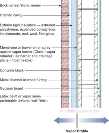
Applicability – all hygro-thermal regions
This is arguably the most durable wall assembly available to architects and engineers. It is constructed from non-water sensitive materials and due to the block construction has a large moisture storage (or hygric buffer) capacity. It can be constructed virtually anywhere. In cold climates condensation is limited on the interior side of the vapor barrier as a result of installing all of the thermal insulation on the exterior side of the vapor barrier (which is also the drainage plane and air barrier in this assembly). In hot climates any moisture that condenses on the exterior side of the vapor barrier will be drained to the exterior since the vapor barrier is also a drainage plane. This wall assembly will dry from the vapor barrier inwards and will dry from the vapor barrier outwards.
Figure 2: Concrete Block With Interior Frame Wall Cavity Insulation and Brick or Stone Veneer
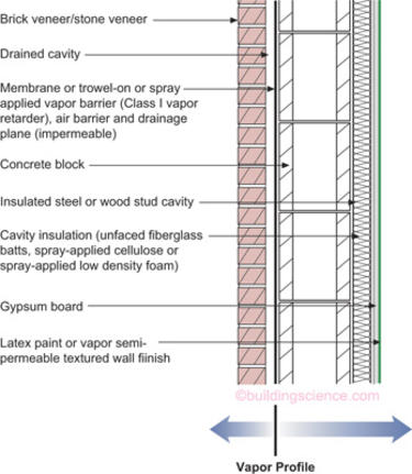
Applicability – Limited to mixed-humid, hot-humid, mixed-dry, hot-dry and marine regions – should not be used in cold, very cold, and subarctic/arctic regions
This wall assembly has all of the thermal insulation installed to the interior of the vapor barrier and therefore should not be used in cold regions or colder. It is also a durable assembly due to the block construction and the associated moisture storage (hygric buffer) capacity. The wall assembly does contain water sensitive cavity insulation (except where spray foam is used) and it is important that this assembly can dry inwards – therefore vapor semi impermeable interior finishes such as vinyl wall coverings should be avoided. In this wall assembly the vapor barrier is also the drainage plane and air barrier.
Figure 3: Concrete Block With Interior Rigid Insulation and Stucco
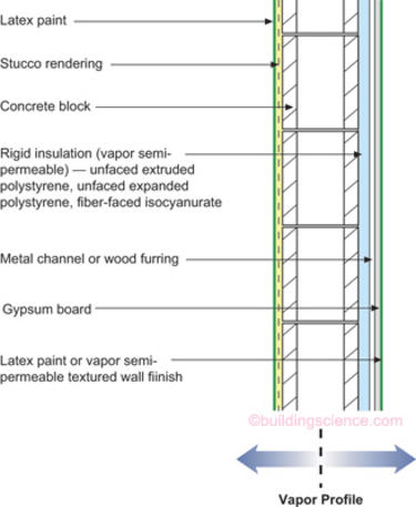
Applicability – all hygro-thermal regions*
This assembly has all of the thermal insulation installed on the interior of the concrete block construction but differs from Figure 2 since it does not have a vapor barrier on the exterior. The assembly also does not have a vapor barrier on the interior of the assembly. It has a large moisture storage (hygric buffer) capacity due to the block construction. The rigid insulation installed on the interior should be non-moisture sensitive and allow the wall to dry inwards—hence the recommended use of vapor semi permeable foam sheathing. Note that the foam sheathing is not faced with aluminum foil or polypropylene skins. It is important that this assembly can dry inwards except in very cold and subarctic/arctic regions—therefore vapor semi impermeable interior finishes such as vinyl wall coverings should be avoided in assemblies – except in very cold and subarctic/arctic regions. Vapor impermeable foam sheathings should be used in place of the vapor semi permeable foam sheathings in very cold and subarctic/arctic regions. The drainage plane in this assembly is the latex painted stucco rendering. A Class III vapor retarder is located on both the interior and exterior of the assembly (the latex paint on the stucco and on the interior gypsum board.
* In very cold and subarctic/arctic regions vapor impermeable foam sheathings are recommended
Figure 4: Concrete Block With Interior Rigid Insulation/Frame Wall With Cavity Insulation and Stucco
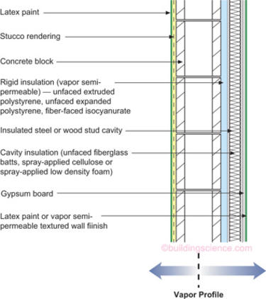
Applicability – all hygro-thermal regions*
This assembly is a variation of Figure 3. It also has all of the thermal insulation installed on the interior of the concrete block construction but differs from Figure 3 due to the addition of a frame wall to the interior of the rigid insulation. This assembly also does not have a vapor barrier on the exterior. The assembly also does not have a vapor barrier on the interior of the assembly. It has a large moisture storage (hygric buffer) capacity due to the block construction. The rigid insulation installed on the interior should be non-moisture sensitive and allow the wall to dry inwards—hence the recommended use of vapor semi permeable foam sheathing. Note that the foam sheathing is not faced with aluminum foil or polypropylene skins. It is important that this assembly can dry inwards even in very cold and sub arctic/arctic regions—therefore vapor semi impermeable interior finishes such as vinyl wall coverings should be avoided in assemblies. Vapor impermeable foam sheathings should be used in place of the vapor semi permeable foam sheathings in very cold and sub arctic/arctic regions. The drainage plane in this assembly is the latex painted stucco rendering. A Class III vapor retarder is located on both the interior and exterior of the assembly (the latex paint on the stucco and on the interior gypsum board.
* In very cold and sub arctic/arctic regions vapor impermeable foam sheathings are recommended – additionally the thickness of the foam sheathing should be determined by hygro-thermal analysis so that the interior surface of the foam sheathing remains above the dew point temperature of the interior air.
Figure 5: Frame Wall With Exterior Insulation and Brick or Stone Veneer
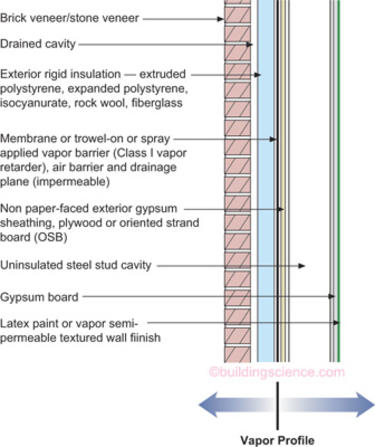
Applicability – all hygro-thermal regions
This wall is a variation of Figure 1—but without the moisture storage (or hygric buffer) capacity. This wall is also a durable wall assembly. It is constructed from non-water sensitive materials and has a high drying potential inwards due to the frame wall cavity not being insulated. It can also be constructed virtually anywhere. In cold climates condensation is limited on the interior side of the vapor barrier as a result of installing all of the thermal insulation on the exterior side of the vapor barrier (which is also the drainage plane and air barrier in this assembly). In hot climates any moisture that condenses on the exterior side of the vapor barrier will be drained to the exterior since the vapor barrier is also a drainage plane. This wall assembly will dry from the vapor barrier inwards and will dry from the vapor barrier outwards.
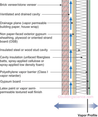
Figure 6: Frame Wall With Cavity Insulation and Brick or Stone Veneer
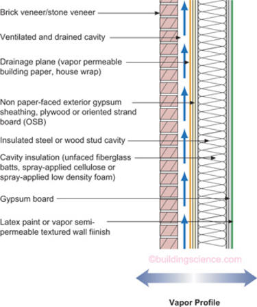
Applicability – Limited to mixed-humid, hot-humid, mixed-dry, hot-dry and marine regions – can be used with hygro-thermal analysis in some areas in cold regions - should not be used in very cold and subarctic/arctic regions
This wall is a flow through assembly—it can dry to both the exterior and the interior. It has a Class III vapor retarder on the interior of the assembly (the latex paint on the gypsum board). It is critical in this wall assembly that the exterior brick veneer (a “reservoir” cladding) be uncoupled from the wall assembly with a ventilated and drained cavity. The cavity behind the brick veneer should be at least 2 inches wide (source: Brick Institute of America) and free from mortar droppings. It must also have air inlets (“weep holes”) at its base and air outlets (“weep holes”) at its top in order to provide back ventilation of the brick veneer. The drainage plane in this assembly is the building paper or building wrap. The air barrier can be any of the following: the interior gypsum board, the exterior gypsum wallboard or the exterior building wrap.
Figure 7: Frame Wall With Cavity Insulation and Brick or Stone Veneer
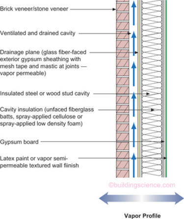
Applicability – Limited to mixed-humid, hot-humid, mixed-dry, hot-dry and marine regions – can be used with hygro-thermal analysis in some areas in cold regions - should not be used in very cold and subarctic/arctic regions
This wall is a variation of Figure 6. The exterior gypsum sheathing becomes the drainage plane. As in Figure 6 this wall is a flow through assembly—it can dry to both the exterior and the interior. It has a Class III vapor retarder on the interior of the assembly (the latex paint on the gypsum board). It is also critical in this wall assembly that the exterior brick veneer (a “reservoir” cladding) be uncoupled from the wall assembly with a ventilated and drained cavity. The cavity behind the brick veneer should be at least 2 inches wide (source: Brick Institute of America) and free from mortar droppings. It must also have air inlets (“weep holes”) at its base and air outlets (“weep holes”) at its top in order to provide back ventilation of the brick veneer. The air barrier in this assembly can be either the interior gypsum board or the exterior gypsum sheathing.
Figure 8: Frame Wall With Exterior Rigid Insulation With Cavity Insulation and Brick or Stone Veneer
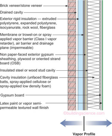
Applicability – all hygro-thermal regions except subarctic/arctic – in cold and very cold regions the thickness of the foam sheathing should be determined by hygro-thermal analysis so that the interior surface of the foam sheathing remains above the dew point temperature of the interior air
This wall is a variation of Figure 5. In cold climates condensation is limited on the interior side of the vapor barrier as a result of installing some of the thermal insulation on the exterior side of the vapor barrier (which is also the drainage plane and air barrier in this assembly). In hot climates any moisture that condenses on the exterior side of the vapor barrier will be drained to the exterior since the vapor barrier is also a drainage plane. This wall assembly will dry from the vapor barrier inwards and will dry from the vapor barrier outwards. Since this wall assembly has a vapor barrier that is also a drainage plane it is not necessary to back vent the brick veneer reservoir cladding as in Figure 6 and Figure 7. Moisture driven inwards out of the brick veneer will condense on the vapor barrier/drainage plane and be drained outwards.
Figure 9: Frame Wall With Cavity Insulation and Brick or Stone Veneer With Interior Vapor Retarder

Applicability – Limited to cold and very cold regions
This wall is a variation of Figure 6 except it has a Class II vapor retarder on the interior limiting its inward drying potential – but not eliminating it. It still considered a flow through assembly—it can dry to both the exterior and the interior. It is critical in this wall assembly—as in Figure 6 and Figure 7—that the exterior brick veneer (a “reservoir” cladding) be uncoupled from the wall assembly with a ventilated and drained cavity. The cavity behind the brick veneer should be at least 2 inches wide (source: Brick Institute of America) and free from mortar droppings. It must also have air inlets (“weep holes”) at its base and air outlets (“weep holes”) at its top in order to provide back ventilation of the brick veneer. The drainage plane in this assembly is the building paper or building wrap. The air barrier can be any of the following: the interior gypsum board, the exterior gypsum board or the exterior building wrap.
Figure 10: Frame Wall With Cavity Insulation and Brick or Stone Veneer With Interior Vapor Barrier
Applicability – Limited to very cold, subarctic and arctic regions
This wall is a further variation of Figure 6 but now it has a Class I vapor retarder on the interior (a “vapor barrier”) completely eliminating any inward drying potential. It is considered the “classic” cold climate wall assembly. It is critical in this wall assembly—as in Figure 6, Figure 7 and Figure 9—that the exterior brick veneer (a “reservoir” cladding) be uncoupled from the wall assembly with a ventilated and drained cavity. The cavity behind the brick veneer should be at least 2 inches wide (source: Brick Institute of America) and free from mortar droppings. It must also have air inlets at its base and air outlets at its top in order to provide back ventilation of the brick veneer. The drainage plane in this assembly is the building paper or building wrap. The air barrier can be any of the following: the interior polyethylene vapor barrier, the interior gypsum board, the exterior gypsum board or the exterior building wrap.
Figure 11: Frame Wall With Cavity Insulation and Stucco
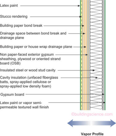
Applicability – Limited to mixed-humid, hot-humid, mixed-dry, hot-dry and marine regions – can be used with hygro-thermal analysis in some areas in cold regions – should not be used in very cold, and subarctic/arctic regions
This wall is also a flow through assembly similar to Figure 6—but without the brick veneer—it has a stucco cladding. It can dry to both the exterior and the interior. It has a Class III vapor retarder on the interior of the assembly (the latex paint on the gypsum board). It is critical in this wall assembly that a drainage space be provided between the stucco rendering and the drainage plane. This can be accomplished by installing a bond break (a layer of tar paper) between the drainage plane and the stucco. A spacer mat can also be used to increase drainability. Alternatively, a textured or profiled drainage plane (building wrap) can be used. The drainage plane in this assembly is the building paper or building wrap. The air barrier can be any of the following: the interior gypsum board, the exterior stucco rendering, the exterior sheathing or the exterior building wrap.
Figure 12: Frame Wall With Cavity Insulation and Stucco With Interior Vapor Retarder
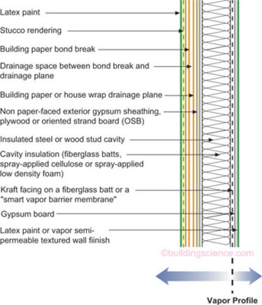
Applicability – Limited to cold and very cold regions
This wall is a variation of Figure 6 and Figure 11 except it has a Class II vapor retarder on the interior limiting its inward drying potential—but not eliminating it. It still considered a flow through assembly—it can dry to both the exterior and the interior. It is critical in this wall assembly – as in Figure 11—that a drainage space be provided between the stucco rendering and the drainage plane. This can be accomplished by installing a bond break (a layer of tar paper) between the drainage plane and the stucco. A spacer mat can also be used to increase drainability. Alternatively, a textured or profiled drainage plane (building wrap) can be used. The drainage plane in this assembly is the building paper or building wrap. The air barrier can be any of the following: the interior gypsum board, the exterior stucco rendering, the exterior sheathing or the exterior building wrap.
Figure 13: Frame Wall With Exterior Rigid Insulation With Cavity Insulation and Stucco
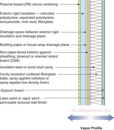
Applicability – all hygro-thermal regions except subarctic/arctic – in cold and very cold regions the thickness of the foam sheathing should be determined by hygro-thermal analysis so that the interior surface of the foam sheathing remains above the dew point temperature of the interior air.
This is a water managed exterior insulation finish system (EIFS). Unlike “face-sealed” EIFS this wall has a drainage plane inboard of the exterior stucco skin that is drained to the exterior. It is also a flow through assembly similar to Figure 6. It can dry to both the exterior and the interior. It has a Class III vapor retarder on the interior of the assembly (the latex paint on the gypsum board). It is critical in this wall assembly that a drainage space be provided between the exterior rigid insulation and the drainage plane. This can be accomplished by installing a spacer mat or by providing drainage channels in the back of the rigid insulation. Alternatively, a textured or profiled drainage plane (building wrap) can be used. The drainage plane in this assembly is the building paper or building wrap. The air barrier can be any of the following: the interior gypsum board, the exterior stucco rendering, the exterior sheathing or the exterior building wrap.
Figure 14: Precast Concrete With Interior Frame Wall Cavity Insulation
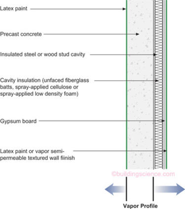
Applicability – Limited to mixed-humid, hot-humid, mixed-dry, hot-dry and marine regions – should not be used in cold, very cold, and subarctic/arctic regions
The vapor barrier in this assembly is the precast concrete itself. Therefore this wall assembly has all of the thermal insulation installed to the interior of the vapor barrier. Of particular concern is the fact that the thermal insulation is air permeable (except where spray foam is used). Therefore this wall assembly should not be used in cold regions or colder. It has a small moisture storage (hygric buffer) capacity due to the precast concrete construction. The wall assembly does contain water sensitive cavity insulation (except where spray foam is used) and it is important that this assembly can dry inwards—therefore vapor semi impermeable interior finishes such as vinyl wall coverings should be avoided. In this wall assembly the precast concrete is also the drainage plane and air barrier.
Figure 15: Precast Concrete With Interior Rigid Insulation

Applicability – all hygro-thermal regions*
This assembly has all of the thermal insulation installed on the interior of the precast concrete. The assembly also does not have a vapor barrier on the interior of the assembly. It has a small moisture storage (hygric buffer) capacity due to the precast concrete construction. The rigid insulation installed on the interior should be non-moisture sensitive and allow the wall to dry inwards—hence the recommended use of vapor semi permeable foam sheathing. Note that the foam sheathing is not faced with aluminum foil or polypropylene skins. It is important that this assembly can dry inwards except in very cold and subarctic/arctic regions—therefore vapor semi impermeable interior finishes such as vinyl wall coverings should be avoided in assemblies – except in very cold and subarctic/arctic regions. Vapor impermeable foam sheathings should be used in place of the vapor semi permeable foam sheathings in very cold and subarctic/arctic regions. The drainage plane in this assembly is the latex painted precast concrete. A Class III vapor retarder is located on both the interior and exterior of the assembly (the latex paint on the stucco and on the interior gypsum board.
* In very cold and subarctic/arctic regions vapor impermeable foam sheathings are recommended
Figure 16: Precast Concrete With Interior Spray Applied Foam Insulation
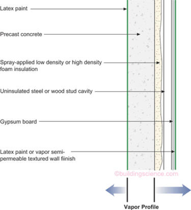
Applicability – all hygro-thermal regions*
This assembly has all of the thermal insulation installed on the interior of the precast concrete. The assembly also does not have a vapor barrier on the interior of the assembly. It has a small moisture storage (hygric buffer) capacity due to the precast concrete construction. The spray foam insulation installed on the interior of the precast concrete is non-moisture sensitive and allows the wall to dry inwards. It is important that this assembly can dry inwards except in very cold and subarctic/arctic regions—therefore vapor semi impermeable interior finishes such as vinyl wall coverings should be avoided in assemblies—except in very cold and subarctic/arctic regions. High-density spray foam, due to its vapor semi impermeable characteristics should be used in place of low-density foam in very cold and subarctic/arctic regions. The drainage plane in this assembly is the latex painted precast concrete. A Class III vapor retarder is located on both the interior and exterior of the assembly (the latex paint on the stucco and on the interior gypsum board.
* In very cold and subarctic/arctic regions high-density spray foam (vapor semi impermeable) is recommended
Roof Assemblies
Figure 17: Vented Attic Flat Ceiling
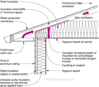
Applicability – all hygro-thermal regions
This assembly can be constructed anywhere. The key to its performance is the airthightness of the ceiling plane—the “air barrier” in this particular assembly. In cold climates and very cold climates a Class II vapor retarder is also required at the ceiling plane. Ventilation is provided with continuous soffit vents and continuous ridge ventilation. The ventilation area is typically according to the 1:300 ratio. In cold climates and very cold climates a water protection membrane is also added at roof perimeters and at valleys to limit water damage associated with ice damming—although the most effective control for ice damming is controlling the temperature of the roof deck by flushing the heat away from the underside by a minimum 2 inch airspace, increasing the depth of insulation at the perimeter and not locating heat producing features in the attic assembly such as air handlers and ductwork or allowing air leakage from the conditioned space.
Figure 18: Conditioned Attic - Cathedralized
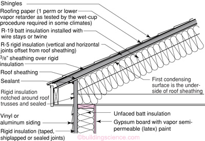
Applicability – all hygro-thermal regions
This assembly can be constructed anywhere. The key to its performance is control of the temperature of the roof deck such that condensation does not occur during winter months. Temperature control of the roof deck is provided by locating a percentage of the thermal insulation above the roof deck such that the temperature of the roof deck is maintained above the design dewpoint temperature of the air vapor mixture within the building enclosure (typically a 45 degree dewpoint). For design purposes the exterior design temperature used is the average temperature of the coldest month of the year—not the heating system design temperature (which is typically the 2.5 percent temperature). A vapor retarder is not located to the interior of this type of assembly permitting inward drying. The advantage of this type of assembly is that ductwork and air handlers can be located in attic spaces that are now conditioned.
Figure 19: Conditioned Attic – Cathedralized Compact
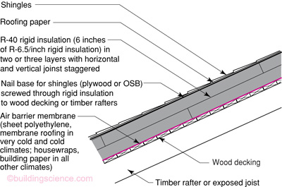
Applicability – all hygro-thermal regions
This assembly can be constructed anywhere. The key to its performance is control of the temperature of the roof deck such that condensation does not occur during winter months. Temperature control of the roof deck is provided by locating all of the thermal insulation above the roof deck. This approach makes this assembly suited for particularly hostile climates such as high elevations and pool enclosures. A Class I vapor retarder can be located on the top of this roof deck in cold and very cold climates. It is recommended that the rigid insulation be installed in two layers with the joints staggered and offset to limit the development of three dimensional airflow pathways. The advantage of this type of assembly is that ductwork and air handlers can be located in attic spaces that are now conditioned.
Figure 20: Conditioned Attic – Cathedralized Air Impermeable Insulation
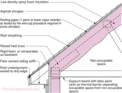
Applicability – all hygro-thermal regions
This assembly can be constructed anywhere. The key to its performance is control of the temperature of the roof deck such that condensation does not occur during winter months. Temperature control of the roof deck is provided by installing and air impermeable insulation to the underside of the roof deck. Air impermeable is defined as 0.02 l/(s-m2)@75 Pa. This level of airtightness can be achieved with spray foam insulations. In cold climates and very cold climates a Class II vapor retarder must be applied in direct contact with the underside of the insulation. This is typically done by spray painting the spray foam insulation with a low perm paint or by selecting a spray foam insulation whose permeance at the applied thickness meets the Class II requirement. A low perm roofing paper is recommended in hot-humid climates to control solar driven moisture where asphalt shingles are used. The advantage of this type of assembly is that ductwork and air handlers can be located in attic spaces that are now conditioned.
Foundation Assemblies
Figure 21: Concrete Basement With Interior Insulation
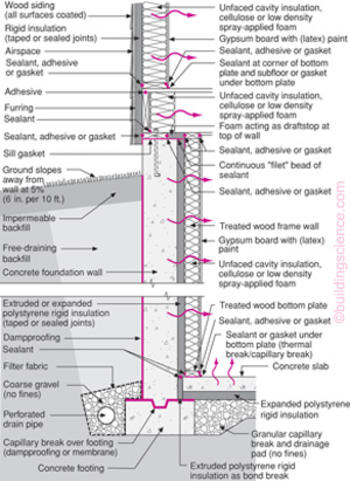
Applicability – all hygro-thermal regions
The key to this assembly is the use of non-water sensitive rigid insulation on the interior that still permits drying to the interior. The recommended permeance of the interior rigid insulation layer is approximately 1 perm. This typically limits the thermal resistance of the interior rigid insulation layer and an insulated frame wall assembly can be located to the interior of the interior rigid insulation. No interior vapor retarder is located within the frame wall permitting inward drying. All interior concrete surfaces are wrapped with the rigid insulation layer—particularly at the top of the wall and at foundation “step downs.” Exterior rigid insulation is located at the rim joist floor framing to control summer condensation. When insulating sheathing is not used, rigid insulation should we installed to the interior of the rim joist or an air impermeable insulation be applied at the rim joist assembly. Note the capillary break at the top of the footing.
Figure 22: Vented Crawlspace
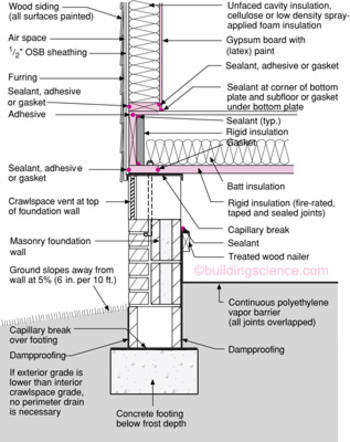
Applicability – all hygro-thermal regions
The key to this assembly is the use of a Class I vapor retarder insulating sheathing at the underside of the floor framing protecting the floor frame assembly. In most regions the exterior air is above the dewpoint temperature of both the ground surface temperature in crawlspaces and the temperature of the floor assembly. The rigid insulation protects the floor assembly from the condensation. A ground cover is also recommended to limit evaporation of water from the soil. The interior grade should be higher than the exterior grade. Floor cavity insulation should be located in contact with the rigid insulation. Rim joists should be internally insulated with rigid insulation to control condensation or an air impermeable insulation should be applied to the interior of the rim joist. Alternatively, exterior insulating sheathing can be used.
Figure 23: Conditioned Crawlspace
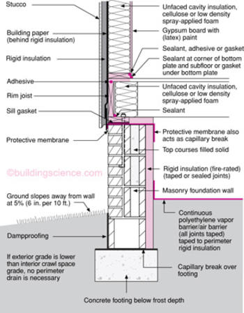
Applicability – all hygro-thermal regions
The key to this assembly is conditioning the crawlspace. A provision for moisture removal must be provided by conditioning the crawlspace with a duct distribution system providing supply and return air or by installing a dehumidifier or by exhaust venting the crawlspace with an exhaust fan. Non water sensitive rigid insulation should be installed at the perimeter and rigid insulation should be installed at rim joist areas (either internally or externally). The interior grade should be higher than the exterior grade. A ground cover should be installed such that it also acts as an air barrier.
Figure 24: Insulated Stem Wall Slab Foundation
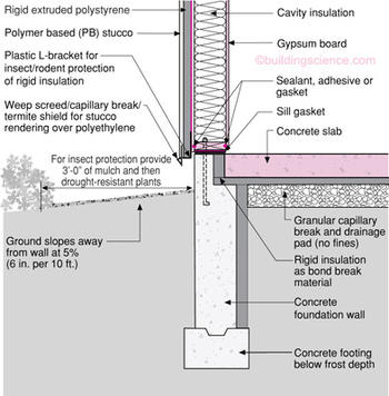
Applicability – all hygro-thermal regions
The key to this assembly is completely thermally uncoupling the concrete slab from the surrounding ground. Note the rigid insulation as a bond break and the full height interior insulation extending from the top of the footing to the underside of the slab as well as the rigid insulation extending horizontally inward. The sill gasket is typically an adhered membrane strip that also provides an air and soil gas seal between the concrete slab and the stem wall.
Figure 25: Externally Insulated Monolithic Slab
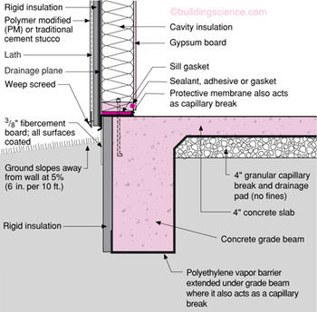
Applicability – all hygro-thermal regions
The key to this assembly is protecting the exterior rigid insulation with a non water sensitive protection board such a fiber cement that is coated on all six surfaces. The protection board should be installed within the formwork prior to placing the concrete so that the insulation is protected from the start of the project. Additionally, the polyethylene vapor barrier should extend under the grade beam so that it can effectively act as a capillary break.
References
- Lstiburek, J.W., Moisture Control For Buildings, ASHRAE Journal, February 2002.
- Samuelson, I. and Samuelson, R., Conditions for Growth of Mold on Wood Products, Swedish Testing Institute, Boras, Sweden, 1990.
- Lstiburek, J.W., Understanding Air Barriers, ASHRAE Journal, July 2005.
- Lstiburek, J.W., Understanding Vapor Barriers, ASHRAE Journal, August 2004.
- Building Air Quality—A Guide for Building Owners and Facility Managers, DHHS (NIOSH) publication No 91-114, Environmental Protection Agency, Washington, DC, December 1991.
- Wilson, A. G., Condensation in Insulated Masonry Walls in Summer, RILEM/CIB Symposium on Moisture Problems in Buildings, NRC 9130, Helsinki, 1965.
- ASHRAE Standard 62.2 Ventilation for Acceptable Indoor Air Quality in Low Rise Residential Buildings, American Society of Heating, Refrigerating, and Air Conditioning Engineers, Inc., Atlanta, 2002.
- Tooley, J. J. and Moyer, N. A., Mechanical Air Distribution and Interacting Relationships, Proceedings, EEBA Conference, Denver, CO, March 1990.
- Tooley, J. J. and Moyer, N. A., Pressure Differential: Measurement of the New Decade, Proceedings, EEBA Conference, Indianapolis, IN, March 1991.
- Rinella, J., Kohli, G., and Timusk, J., “Impact of Residential Air Supply and Demand on Ventilation of Gas Appliances,” Proceedings, 1986 International Gas Research Conference, Toronto, Ontario, 1986.
- Handegord, G. O., Prediction of the Moisture Performance of Walls, ASHRAE Transactions, Vol. 91, 1985.
- Fundamentals Volume—ASHRAE Handbook, American Society of Heating, Refrigerating, and Air Conditioning Engineers, Inc., Atlanta, 2005.
- Baker, M. C., Roofs: Design, Application and Maintenance, Multi-Science Publications, Ltd., Montreal, Canada, 1980.
- Lstiburek, J. W., “Insulation Induced Paint and Siding Failures,” Journal of Thermal Insulation, Vol. 13, January 1990.