Roofs can be designed and constructed to be either vented or unvented in any hygrothermal zone. Air barrier systems are typically the most common approach, however, air pressure control approaches are becoming more common especially in cases involving remedial work on existing structures. Vapor diffusion should be considered as a secondary moisture transport mechanism when designing and building roofs. Specific vapor retarders are often unnecessary if appropriate air movement control is provided or if control of condensing surface temperatures is provided.
Roofs can be designed and constructed to be either vented or unvented in any hygro-thermal zone.
In cold climates, the primary purpose of attic ventilation is to maintain a cold roof temperature to avoid ice dams created by melting snow, and to vent moisture that moves from the conditioned space to the attic. Melted snow, in this case, is caused by heat loss from the conditioned space.
In hot climates, the primary purpose of attic ventilation is to expel solar heated hot air from the attic to lessen the building cooling load.
The amount of roof cavity ventilation is specified by numerous ratios of free vent area to insulated ceiling area ranging from 1:150 to 1:600 depending on which building code is consulted, the 1:300 ratio being the most common. Control of ice dams, moisture accumulation and heat gain can also be facilitated by unvented roof design.
Approach
In cold climates the main strategy that should be utilized when designing roofs to be free from moisture problems and ice dams along with control of heat gain or heat loss regardless of ventilation approach is the elimination of air movement, particularly exfiltrating air. This can be accomplished by the installation of an air barrier system or by the control of the air pressure difference across the roof system.
Air barrier systems are typically the most common approach, however, air pressure control approaches are becoming more common especially in cases involving remedial work on existing structures.
Vapor diffusion should be considered as a secondary moisture transport mechanism when designing and building roofs. Specific vapor retarders are often unnecessary if appropriate air movement control is provided or if control of condensing surface temperatures is provided.
Vented Roof Design
Vented roofs should not communicate with the conditioned space — they are coupled to the exterior. Therefore, an air barrier at the ceiling line should be present to isolate the attic space from the conditioned space. No services such as HVAC distribution ducts, air handlers, plumbing or fire sprinkler systems should be located external to the air barrier (Figure 1).
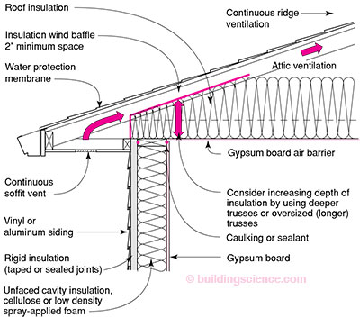
Figure 1: Vented Roof Assembly—Roof insulation thermal resistance (depth) at trus heel (roof perimeter) should be equal or greater to thermal resistance of exterior wall; 1:300 roof ventilation ratio recommended
The recommended ventilation ratio to provide in vented roof assemblies when an air barrier is present, is the 1:300 ratio (as specified by most codes).
In vented cathedral ceiling assemblies a minimum 2-inch clear airspace is recommended between the underside of the roof deck and the top of the cavity insulation. This not a code requirement but ought to be (only 1-inch is typically specified).
In addition to an air barrier at the ceiling line, a Class II vapor retarder should be installed in Climate Zone 6 and Climate Zone 7. A Class III vapor retarder is acceptable in Climate Zone 5.
Class I vapor retarders (i.e. vapor barriers) can be installed in vented roof assemblies in Climate Zone 6 and Climate Zone 7 but should be avoided in Climate Zone 5 as top side condensation may occur in the summer months during air conditioning periods.
No interior roof assembly-side vapor control is required or recommended in climate zones other than cold or very cold.
Unvented Roof Design
Unvented roof design falls into two categories: systems where condensing surface temperatures are controlled and systems where condensing surface temperatures are not controlled. The two categories essentially are the demarcation between regions where cold weather conditions occur with sufficient frequency and intensity that sufficient moisture accumulation from interior sources can occur on an uninsulated roof deck to risk mold, corrosion and decay problems.
The key is to keep the roof deck — the principle condensing surface in roof assemblies — sufficiently warm throughout the year. This can be accomplished either because of the local climate or as a result of design principally through the use of rigid insulation installed above the roof deck or air-impermeable spray foam insulation installed under the roof deck in direct contact with it.
Where rigid insulation is installed above the roof deck, or air-impermeable spray foam insulation is installed under the roof deck condensing surface temperatures are said to be controlled.
The demarcation is specified as a distinction between regions where the monthly average temperature remains above 45 degrees F throughout the year and where it drops below 45 degrees F during the year. An additional criteria is also necessary - that of keeping interior relative humidities below 45 percent.
These criteria were selected for two reasons. First, by keeping the roof deck above 45 degrees F, condensation can be minimized or eliminated. Condensation will not occur unless the dewpoint temperature of the interior air exceeds 45 degrees F and this air contacts the roof deck. This interior dewpoint temperature is approximately equal to an interior conditioned space temperature of 70 degrees F at an interior relative humidity of 45 percent. These are interior moisture conditions that can easily be avoided with air change/ventilation or the avoidance of over humidification during the coldest month of the year in the climate zones specified.
Second, a monthly average temperature was selected, rather than a design heating temperature, as it is more representative
of building enclosure performance. Short term, intermittent "spikes" in parameters/environmental loads are of interest to structural engineers and in the sizing of equipment, but not typically relevant to moisture induced deterioration. Wood-based roof sheathing typical to residential construction has sufficient hygric buffer capacity to absorb, redistribute and re-release significant quantities of condensed moisture should intermittent condensation occur during cold nights when the sheathing temperature occasionally dips below 45 degrees F. The average monthly conditions more accurately reflect moisture content in wood-based assemblies.
Asphalt roofing shingles require special attention when installed on unvented roof assemblies in hot-humid, mixed-humid and marine climates due to inward vapor drive from incident solar radiation. A 1 perm or lower vapor retarder (Class II) as tested by the wet-cup procedure should be installed under the asphalt roofing shingles to control this inward drive.
Wood shingles or shakes, require a minimum 1/4-inch vented airspace that separates the shingles/shakes and the roofing felt placed over the roof sheathing for similar reasons.
The demarcation between regions that require the control of condensing surface temperatures and regions that do not can be obtained by using the hygro-thermal zones definitions in this builder's guide. Both hot-humid and hot-dry climate zones meet the 45°F roof deck criteria. However, the high interior humidities found in buildings located in hot-humid zones during the winter months do not always meet the 45% interior relative humidity criteria. Therefore, the only zone that meets both of these requirements is the hot-dry hygro-thermal region. Only hot-cry climates do not require the control of condensing surface temperatures. All other regions require some form of control.
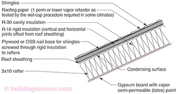
Control of condensing surface temperatures typically involves the installation of insulating sheathing above the roof deck. In residential wood frame construction this involves installing rigid insulation between the roof shingles and the roof plywood or OSB (Figure 2). The installation of the rigid insulation elevates the temperature of the roof deck to minimize condensation.
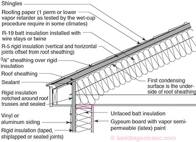
Figure 2: Rigid Insulation Used to Control Condensing Surface Temperatures—Rigid insulation installed above roof deck; ratio of R-value between rigid insulation and batt insulation is climate-dependent
In cold and very cold climates selecting a roof deck condensing surface temperature criteria of 45°F is very conservative. This temperature criteria can be reduced to 40°F (which corresponds to interior average conditions of 70°F, 35% RH) where high interior moisture loads due to spas, indoor swimming pools and excessive humidification are not present.
Figure 3 and Figure 4 illustrate the differences between the two fundamental systems. Figure 3 shows the potential for condensation of an unvented roof assembly in Phoenix, AZ. Phoenix, AZ is located in a hot-dry climate zone. This roof assembly has no insulating sheathing installed above the roof deck.
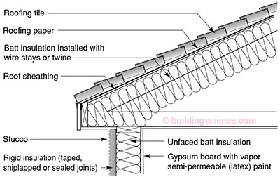
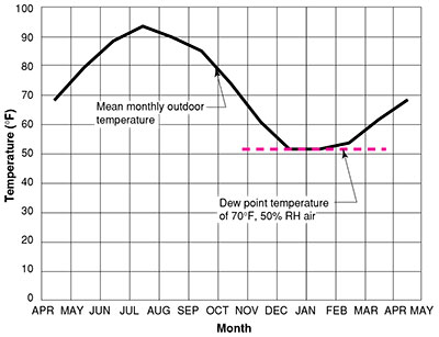
Figure 3: Potential for Condensation in Phoenix, Arizona with Unvented Roof—1,750 heating degree days; winter design temperature 34°F; summer design temperature 107°F dry bulb and 71°F wet bulb; there is no potential for condensation on the underside of the roof sheathing until interior moisture levels exceed 50% RH at 70°F
Figure 4 shows the potential for condensation of an unvented roof assembly in Dallas, TX. Dallas, TX is located in a mixed-humid climate zone. Note that this roof assembly has rigid insulation installed above the roof deck in order to control the condensation potential. The thermal resistance of the rigid insulation (thickness) necessary to control condensation depends on the severity of the climate. The colder the climate, the greater the resistance of the rigid insulation required. Note that the thermal resistance of the rigid insulation is based on the ratio of the thermal resistance of the insulation above the roof deck as compared to the thermal resistance of the insulation below the roof deck. The key is to elevate the temperature of the condensing surface to 45 degrees F or higher during the coldest months of the year.
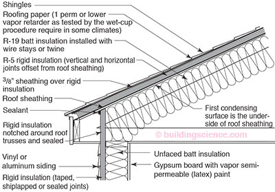
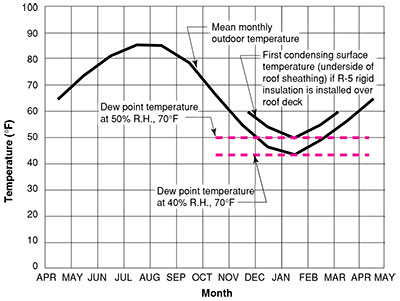
Figure 4: Potential for Condensation in Dallas, Texas with Unvented Roof and Insulating Sheathing—There is no potential for condensation on the underside of the roof sheathing until moisture levels exceed 40% RH at 70°F; rigid insulation is recommended in this roof assembly to raise the condensation potential above 50% RH at 70°F
Figure 5 shows the use of rigid insulation in a cathedral ceiling assembly in Washington, DC. A calculation procedure is presented that determines the temperature of the condensing surface. This calculation procedure is similar to the one used in Chapter 4 to determine the sheathing temperature in wall assemblies.
| Inside Temp. | Monthly Average Outdoor Temp. | ΔT | Temperature of Condensing Surface |
R-46 Unvented Roof Assembly—Two layers of | |
| Oct | 70 | 55 | 15 | 60 | |
| Nov | 70 | 45 | 25 | 54 | |
| Dec | 70 | 36 | 34 | 48 | |
| Jan | 70 | 31 | 39 | 45 | |
| Feb | 70 | 34 | 36 | 47 | |
| Mar | 70 | 43 | 27 | 52 | |
| Apr | 70 | 49 | 21 | 56 | |
Ratio of thermal resisistance above condensing surface to total thermal resistance 16 ÷ 46 = 0.348 | |||||
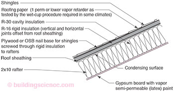
Figure 5: Condensing Surface Temperature in Washington, DC—The greater the thermal resistance in the cavity, the lower the temperature of the condensing surface; the greater the thermal resistance of the rigid insulation, the higher the temperature of the condensing surface; in designs with no cavity insulation, only rigid insulation, yield the highest (warmest) condensing surface temperatures; in hot-humid, mixed-humid and marine climates a 1 perm or lower vapor retarder as tested by the wet-cup procedure should be installed under the asphal roofing shingles
Figure 6 plots the temperature of the condensing surface. The graph shows that condensation within the roof assembly will not occur if interior conditions are maintained at 45 percent relative humidity or less at 70 degrees F during the coldest month of the year.
 | R-46 Unvented Roof Assembly—Two layers of R-6.5/inch rigid insulation yielding a total combined thickness of 2.5 inches; layers of rigid insulation have staggered joints to facilitate airtightness; two layers are preferable to one layer due to increase in air flow resistance |
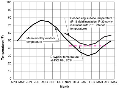 | There is no potential for condensation until interior moisture levels exceed 45% RH at 70°F during the coldest month of the year if R-16 rigid insulation is installed over rafter cavity iinsulation to R-30; in hot-humid, mixed-humid and marine climates a 1 perm or lower vapor retarder as tested by the wet-cup procedure should be installed under the asphalt roofing shingles |
Figure 6: Potential for Condensation in Washington, DC with Rigid Insulation in Unvented Roof Assembly
Figure 7 shows a roof design that is not as dependent on controlling interior moisture levels as the other roof designs presented. The absence of cavity insulation yields the highest condensing surface temperature of any of the designs presented. In this particular design, the condensing surface is the air barrier membrane installed over the wood decking. With this design interior relative humidities should be kept below 60 percent in order to control surface mold. In cold and very cold climate zones where there is likely snow accumulation on roof surfaces, there is also the likelihood of ice-damming. In order to control ice-damming, heat flow form the interior to the roof cladding must be minimized. In cold climate zones the minimum total R-value for the entire unvented roof assembly should be R-40. In very cold climate zones this minimum R-value should be increased to R-50.
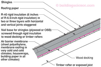
Figure 7: Compact Unvented Roof Assembly—R-value increased to R-50 in very cold climate zones to control ice-damming; optimum roof assembly design to enclose pool areas and spas
In extreme snow regions it is typical to add a vented air space between the roof cladding (shingles) and the rigid insulation in Figure 7 to flush heat away trapped due to the insulating value of the snow (the snow becomes an insulating "blanket"). In essence creating a vented-unvented hybrid roof assembly.
Note that in these types of unvented roof assemblies (except Figure 7), interior vapor barriers (Class I vapor retarders) are not recommended as these assemblies are expected to be able to "dry" towards the interior.
Instead of installing rigid insulation above the roof deck to control condensing surface temperature, air-impermeable spray foam insulation can be installed in direct contact to the underside of the roof deck to accomplish the same thing.
Figure 8 shows a roof design where air-impermeable spray foam insulation is installed in direct contact to the underside of the structural roof deck.
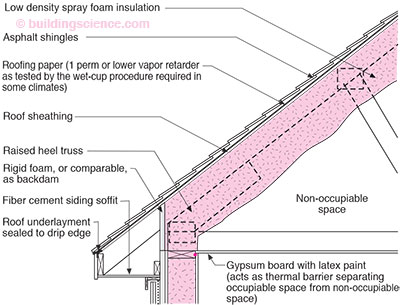
Figure 8: Air Impermeable Spray Foam Insulation—Spray foam protected with thermal barrier in occupied attic space; in hot-humid, mixed-humid and marine climates a 1 perm or lower vapor retarder as tested by the wet-cup procedure should be installed under the asphalt roofing shingles
In Climate Zone 6 and Climate Zone 7 the air-impermeable insulation, including any covering adhered continuously to the bottom side should have a vapor permeance of 1 perm or less (i.e. have the characteristics of a Class II vapor retarder or lower). This can be done by applying vapor barrier paint over the interior surface of the low density spray foam or by installing a material layer that has a vapor permeance of 1 perm or less.
A high density spray foam insulation due to its impermeability properties can be installed directly under roof decks in Climate Zone 6 and Climate Zone 7 without any additional provision for vapor diffusion resistance.
In Figure 9 extruded polystyrene of thickness 1-inch is installed to provide a Class II vapor retarder on the bottom side of the low density air-impermeable spray foam insulation. This allows the assembly to be constructed in Climate Zone 6 and Climate Zones 7. Without the extruded polystyrene layer (or without a coating of vapor barrier paint) the use of low density air-impermeable spray foam insulation is limited to Climate Zone 5 or lower.
Gypsum board is used to provide a thermal barrier with foam insulations to meet code requirements when an attic space is occupiable.
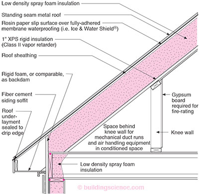
Figure 9: Air Impermeable Spray Foam Insulation—Spray foam protected with thermal barrier in occupied attic space; interior vapor retarder (Class II) required with low density spray foam in Climate Zones 6 and 7
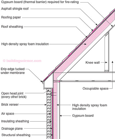
Figure 10: Air Impermeable Spray Foam Insulation—Spray foam protected with thermal barrier in occupied attic space; high density foam insulation partially fills roof rafter cavity and wall cavity; no interior vapor retarder required in any climate zone with high density spray foam insulation
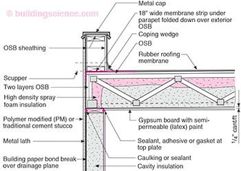
Figure 11: Unvented Flat Roof Assembly—There is no potential for condensation on the underside of the roof sheathing until interior moisture levels exceed 50% RH at 70°F; high density spray foam insulation does not require an interior vapor retarder in any climate
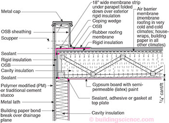
Figure 12: Unvented Flat Roof Assembly: Condensing Surface Temperature Controlled—The thickness of the rigid insulation at both the roof deck and perimeter is determined by a calculation procedure similar to Figure 5; the colder the climate, the thicker the rigid insulation required; the higher the interior moisture level, the thicker the rigid insulation required