Air flow in buildings is one of the major factors that governs the interaction of the building structure with the mechanical system, climate and occupants. If the air flow at any point within a building or building assembly can be determined or predicted, the temperature and moisture (hygrothermal or pyschometric) conditions can also be determined or predicted. If the hygrothermal conditions of the building or building assembly are known, the performance of materials can also be determined or predicted.
Introduction
Air flow in buildings is complex, time dependent and multi-directional. The understanding of air flow through and within buildings has been based on the requirement for continuity of mass and momentum caused by wind forces, thermal effects (stack action) and forces associated with the operation of mechanical cooling, heating, exhaust and other ventilation systems.
Interstitial air flow and interstitial air pressure fields are not often considered. Building analysis typically develops the building pressure field from the air flow field. In doing so exterior and interior walls, floors, and roof assemblies are either considered as monolithic or having openings resulting in flow across the specific assemblies.
Many problems associated with pollutant transfer, smoke and fire spread cannot be explained by cross assembly (one dimensional) air flow as well as such moisture effects as microbial contamination, corrosion and biological decay. Even the analysis of energy consumption and comfort within buildings needs to be considered in terms of multi-directional air flow.
Buildings typically comprise multi-layer envelope assemblies with numerous air gaps or void spaces that are often connected to service chases. Complex three dimensional flow paths and intricate air pressure relationships must be considered.
Context
Air flow in buildings is complex, time dependent and multi-directional. The understanding of air flow through and within buildings has assumed that wind forces, thermal effects (stack action), and air movement associated with mechanical cooling, heating and exhaust and other ventilation systems are the dominant factors relating to air pressure relationships and air pressure related building performance.
In principle, this view is correct, though often too simplistic. Under this view, the wall assemblies, roof assemblies, interior floors and demising walls/partitions are treated either as monolithic or having through-the-assembly openings. Air flow has been assumed to occur across these assemblies, from one side to the other based on the air pressure difference across them, typically through simple leakage areas resulting in one dimensional air flow.
Actually, exterior wall, roof, interior floor and interior wall/partition assemblies are often hollow or multi-layered with numerous air gaps or void spaces and can operate under air pressure regimes (fields) that are largely independent of the air pressures on either side of them. Typical buildings also contain numerous service chases that provide complex three-dimensional linkage among the exterior wall, roof, interior floor and interior wall/partition assembly cavities and void spaces. These interstitial air pressure fields within building assemblies and their linkage to chases and service cavities can lead to lateral flow paths or more intricate three dimensional flow paths that may or may not connect to the interior or exterior spaces that the building assemblies separate.
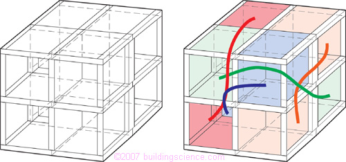
Figure 1: Three dimensional multi-layer multi-cell analogue (left)
with air pressure fields connecting non-contiguous spaces illustrated (right)
As a result of these interstitial air pressure fields, direct cross assembly (one-dimensional) air flow does not always hold. To account for the presence of interstitial air pressure fields air flow must be added or subtracted within an assembly, chase or void space. In this manner, continuity of mass and momentum holds across the volume of the assembly or element.
The interstitial air pressure fields often vary with time with complex daily, weekly, seasonal and sometimes random cycles. They are often, but not always, driven by fan forces coupled with duct leakage. Thermal effects, moisture effects and wind forces can also be interstitial air pressure field drivers depending on the linkages of interstitial flow paths. These time variable interstitial air pressure fields help characterize the dynamic characteristics of the pressure response of buildings.
The presence of complex, time dependent interstitial air pressure fields and associated lateral or three dimensional flow paths can lead to complex interactions of the building structure with the mechanical system and climate. Understanding the complex interactions of the building pressure field - the air pressure regime within and surrounding the building - helps explain the increasingly common failures related to:
- indoor air quality, sick building syndrome, building related illness;
- smoke and fire spread;
- condensation, corrosion, decay and mold;
- comfort (temperature, humidity and odors);
- operating costs (energy consumption, maintenance and housekeeping).
Building Air Pressure Field
The building air pressure field (static plus dynamic) - the total air pressure regime within and surrounding the building - involves four contributing air pressure fields:
- exterior field;
- interior field;
- interstitial field;
- air conveyance system field.
The exterior field extends from infinity to the exterior skin of the building envelope. The remaining three component fields are inward of the exterior skin of the building envelope except in the special case of ductwork associated with the air conveyance system field that is located to the building exterior.
When considering the exterior field, the boundary layer at the building envelope surface is typically of primary significance in building analysis. The above grade portion of the exterior field is typically dominated by wind-induced flows (Figures 2 and 3). The below grade portion of the exterior field is a function of the soil characteristics (air porosity), the footprint of the building, the interaction with the building and time dependent atmospheric pressures in the vicinity of the building (Figure 4).
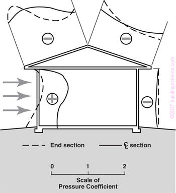
Figure 2: Exterior air pressure field (from Hutcheon and Handegord, 1983)
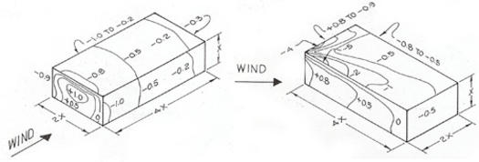
Figure 3: Pressure coefficients on walls and roof of rectangular
buildings without parapets (ASHRAE Handbook of Fundamentals)
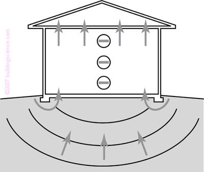
Figure 4: Exterior air pressure field extending
below grade (from Hutcheon and Handegord, 1983)
The interior field occurs within spaces such as rooms, corridors, stairwells, and elevator shafts (Figure 5) and is dominated by the operation of air conveyance systems, the stack effect and wind. The interior field is typically bounded by the interstitial air pressure field except in the special case of monolithic, solid, non porous walls, floors and roofs.
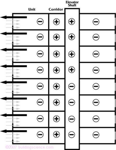
Figure 5: Interior air pressure field
The interstitial field occurs within a building cavity such as an exterior or interior wall assembly, roof assembly or floor assembly (Figure 6). The interstitial field is bounded by the exterior field and the interior field and is often dominated by the leakage of air conveyance systems and building leakage pathways.
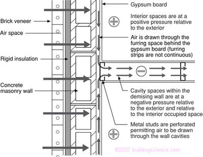
Figure 6: Interstitial air pressure field
The air conveyance system field occurs within the ductwork of forced-air thermal distribution systems, chimneys, air exhaust and air supply systems (Figure 7) and is dominated by the size and capacity of duct work, fans and blowers and temperature differentials. It is bounded by the other three pressure fields.
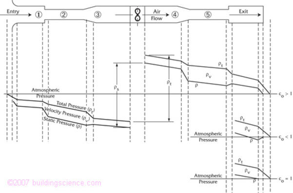
Figure 7: Air conveyance air pressure field
These air pressure fields are coupled and interact dynamically. The interstitial field provides linkage between the exterior field, the interior field and the air conveyance system field.
Dynamic Interaction of Component Fields
A hotel room/bathroom suite with an exhaust grill, a fan coil unit, corridor make-up air and steel stud partition walls provides a good example of the dynamic interaction of the component fields and the limitations of traditional analysis (Figure 8).
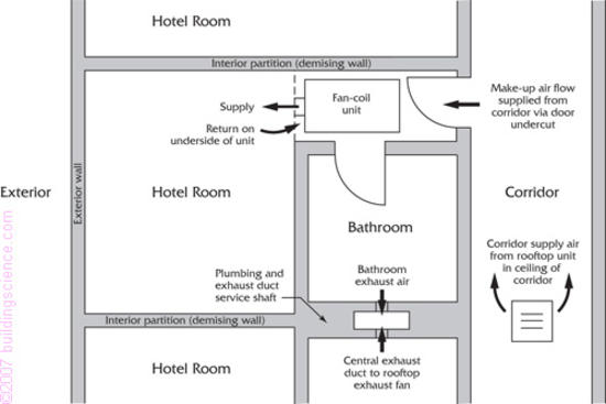
Figure 8: Hotel room/bath suite plan view
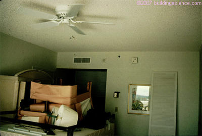
Photograph 1: Typical hotel room/bath suite
As is common in hotel construction, a fan coil unit is suspended from the ceiling and enclosed in a gypsum board dropped ceiling enclosure. The dropped ceiling enclosure is designed as a return air plenum. The fan coil unit provides heating and cooling to the hotel room by pulling air from the room through a return grille located at the underside of the dropped ceiling enclosure, conditioning the air, and returning the air through a supply register located in the face of the dropped ceiling enclosure. These units typically supply 1.75 to 2.5 kilowatts of heating and cooling and typically move approximately 100 to 150 L/s of air. Under conventional thinking, this fan coil unit only recirculates air and therefore does not affect the air pressure relationships in the room (Figure 9).
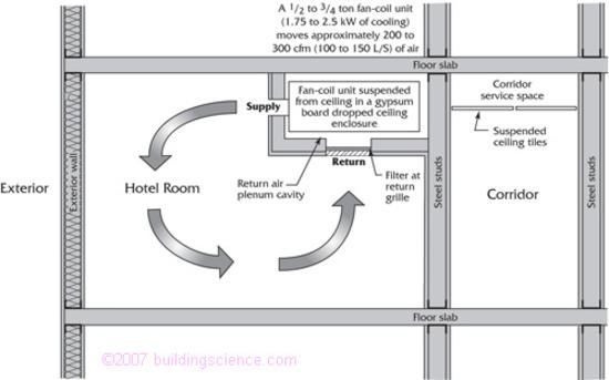
Figure 9: Hotel room/bath suite section view
Additionally, an exhaust grill is located in the bathroom of each hotel room suite. This exhaust grill is typically connected to a central exhaust duct extending to a roof top exhaust fan. The roof top exhaust fan often serves several hotel room suites via the central exhaust duct. This exhaust fan typically runs continuously, although in some facilities, timer controlled operation occurs. Air which is exhausted from the hotel room/bathroom suite by this exhaust fan is intended to be replaced with make-up air supplied from the corridor. The main HVAC system typically supplies sufficient conditioned make-up air to the corridor to supply all of the hotel room suites served by the corridor. Make-up air from the corridor is intended to enter the hotel rooms by passing under the door between the room and the corridor. This door is undercut to provide passage of air from the corridor to the room (Figure 10).
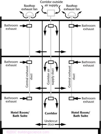
- Air exhausted from bathrooms via central rooftop exhaust fans.
- Air supplied from corridors via undercut doors.
Design Intent
The design intent typically calls for the hotel room to be pressurized relative to the exterior. The reason for pressurization to be called for in the design intent is the control of infiltrating hot, humid air during cooling periods, the exclusion of exterior pollutants and the minimization of drafts during heating periods. Standard practice calls for supplying approximately 15 percent more air to a room than is exhausted to accomplish this. For example, if the exhaust flow out of the bathroom is 25 L/s, the design make-up air to be supplied to the hotel room/bathroom suite through the door undercut is approximately 30 L/s.
Typical Problem and Traditional Analysis
Mold contamination under vinyl wall coverings is an increasingly common problem in interior partition wall assemblies associated with buildings constructed as described in Figure 8, Figure 9 and Figure 10. The investigation of such a problem is typically instigated by one or a combination of the following symptoms:
- the room smells;
- the humidity levels within the room are excessive;
- the vinyl wall covering becomes discolored with pink or maroon stains;
or
- the gypsum board is soft and water logged.
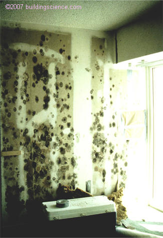
Photograph 2: Vinyl wall covering removed to expose mold on hotel room wall
Using traditional analysis, an investigation of the moisture damage in an unoccupied hotel room as described proceeds along the following path:
The capacity of the fan-coil unit is checked to ensure that it is not oversized. Oversized fan-coils are known to have short duty-cycles. Short duty-cycles are incapable of removing significant quantities of air borne moisture. The fan-coil units are typically required to have sufficient latent capacity to remove moisture generated by occupants within the hotel rooms due to respiration and to remove moisture entering by vapor diffusion through the building envelope. In this particular example let us assume that the fan-coil unit has been sized correctly.
The capacity and operation of the central exhaust system is checked against the capacity and operation of the roof-top make-up air unit. Exhaust flow rates are measured with a flow hood and compared to the supply air flow rate (make-up air) provided by the roof-top unit to the corridors. A pitot tube or hot wire anemometer is used to measure supply flow at the roof-top unit. Exhaust fan operation is typically inter-locked with the roof-top make-up air unit. This inter-lock is checked. The intent is to assure that more air is supplied by the roof top unit to the corridors than is exhausted out of the rooms by the central exhaust fans in order to avoid negative air pressures within the hotel rooms with respect to the exterior. This is desirable to control infiltration of exterior humid air and the associated latent load. In this particular example let us assume that positive pressurization is achieved within the hotel room by the operation of the roof-top unit while the central exhaust system is operating. This is verified with a smoke pencil at the exterior window and by summing the measured exhaust flows from the bathroom/suites served by the corridor and comparing this flow to the measured supply air flow to the corridor.
The intent of the bathroom exhaust flow is to handle odors and moisture generated within the bathroom due to showers and bathing. A smoke pencil shows that air is pulled into the bathroom under the bathroom door. The quantity of air extracted from the bathroom via the central exhaust system (as measured by a flow hood) is approximately 25 L/s. This matches the design intent and is known by experience to be able to handle typical bathroom moisture loads and odors.
The relative humidity and temperature in the corridor are measured and recorded as follows: 55 percent relative humidity and 23 degrees C or a dew point temperature of approximately 14 degrees C. This matches the design intent for the roof top unit to supply “neutral temperature air at a neutral relative humidity.”
The exterior relative humidity and temperature are measured and recorded as follows: 60 percent relative humidity and 32 degrees C. or a dew point temperature of approximately 24 degrees C. This is an expected condition for August in the location the hotel is constructed.
The relative humidity within the hotel room is measured as fluctuating between 65 percent and 75 percent relative humidity. The interior hotel room temperature varies between 23 degrees C. and 27 degrees C. This corresponds to dew point temperatures of between 16 degrees C and 20 degree C. The interior room air moisture levels are unexpectedly high and not explainable. The interior room air moisture levels should match the corridor moisture levels, especially if rooms are unoccupied. Recall that the rooms are at a positive air pressure with respect to the exterior so that infiltration of exterior moisture laden air is eliminated as a moisture source using traditional analysis and that vapor diffusion from the exterior through the exterior wall is negligible.
The possibility of rain water leakage through the building envelope is examined. The possibility of roof leakage is examined. Let us assume that no rain water leakage through wall or roof assemblies is occurring.
At this point the investigation and analysis typically breaks down. More often than not moisture of construction is assumed to be the culprit and the contractor is blamed for not covering the work during construction and preventing rain wetting of the materials. This argument is typically eroded if the hotel is more than a few years old and no explanation what-so-ever is provided.
Examining the Pressure Fields
Hotel building envelope and interior wall construction are typically steel studs with gypsum board (Figure 11). Steel studs are perforated with punched openings to facilitate installation of services. These perforations create a connected wall cavity in both interior and exterior walls. In exterior walls, fiberglass batt insulation is installed. As fiberglass batt insulation provides very small resistance to air flow, the connected wall cavity construction in both interior and exterior walls permits considering these walls as acting as air ducts.
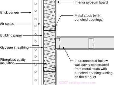
Figure 11: Wall construction plan view
When examining the pressure fields, the investigation of the moisture damage in an unoccupied hotel room as previously presented proceeds along the following path:
The air pressures within the partition walls relative to the exterior are measured with a manometer. Additionally, the air pressure within the room relative to the exterior is measured. The partition wall on one side of the room is measured to be operating under a varying negative air pressure with respect to the exterior between 1 Pa. and 2 Pa. This pressure fluctuates based on the opening and closing of the bathroom door. The partition wall on the opposite side of the room varies between a positive air pressure of 1 Pa. and a negative air pressure of 1 Pa. to the exterior. This pressure fluctuates based on the duty cycle of the fan-coil. The room is measured to have a positive air pressure with respect to the exterior that varies between 1 Pa. and 2 Pa. based on the duty cycle of the fan-coil.
At this point the investigation is essentially complete. The interpretation of the results follow.
Air Pressure Driver 1: Fan Coil
In the example described in Figure 8 and Figure 9, the fan coil unit extracts air out of the dropped ceiling assembly because the dropped ceiling enclosure is designed to act as a return plenum. Resistance to air flow is provided by a filter in the return grill creating a negative pressure within the dropped ceiling enclosure relative to its surroundings. However, dropped ceiling enclosures are seldom air tight due to numerous penetrations for controls, power supply, and piping. Additionally, joints and seams in the materials forming the dropped ceiling enclosure are difficult to make airtight.
The dropped ceiling enclosure is connected to the partition wall via the penetrations for controls, power supply, piping and through openings reflective of the prevailing construction practice. The partition wall is further connected to the exterior wall. A negative air pressure field is created in the partition wall relative to the rooms on both sides due to its connection to the dropped ceiling plenum. This negative air pressure field extends to the exterior wall and may or may not be negative with respect to the exterior.
If this air pressure field within the partition wall is also negative with respect to the exterior, it leads to the infiltration of hot humid air during cooling periods and contaminants during other periods through the exterior wall assembly, down the demising wall to the dropped ceiling assembly (Figure 12). During cooling periods when this air is cooled due to the cooling of the hotel rooms on both sides of the partition wall, moisture is deposited in the wall cavities leading to mold and microbial contamination.
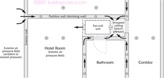
Figure 12: Pressure field due to fan-coil unit
- Room is at positive air pressure relative to exterior-driven air from corridor and air supplied to room from fan-coil unit pulling air from exterior through demising wall.
- Fan-coil unit depressurizes dropped ceiling assembly due to return plenum design.
- Demising wall cavity pulled negative due to connection to dropped ceiling return plenum.
This negative air pressure field in the interstitial spaces exists only when the fan coil unit is operating and exists despite the positive air pressure in the hotel room created by the air flow from the corridor. This interstitial negative air pressure field is time dependent and is related to the duty cycle of the fan coil unit.
The partition wall acts as an outside air duct supplying outside air to the fan coil. This outside air supply tends to increase the positive air pressure in the room with respect to the exterior. This causes fluctuation in the positive pressure (with respect to the exterior) in the room in synchronization with the duty cycle of the fan-coil. It also leads to elevated levels of air borne moisture within the room.
Air Pressure Driver 2: Central Exhaust
In a similar manner to the fan coil unit induced interstitial partition wall depressurization, leakage of the central exhaust duct located within the plumbing service shaft also leads to the creation of a negative air pressure field relative to the rooms in the opposite demising wall that also extends to the exterior wall. This negative air pressure field exists only when the roof top exhaust fan operates and again exists despite the positive air pressure in the hotel room (Figure 13). When the bathroom door is closed, the flow path from the suite to the exhaust grill in the bathroom is interrupted creating a flow resistance resulting in more air to be extracted from the partition wall. This results in increased depressurization within the partition wall on a cycle matched to the opening and closing of the bathroom door.
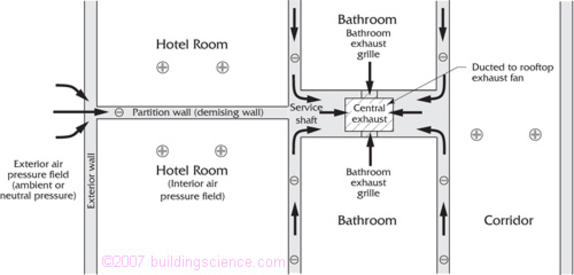
Figure 13: Pressure field due to central exhaust plan view
Leakage of central exhaust duct pulls air out of service shaft depressurizing shaft and demising walls.
The negative air pressure field due to the roof top exhaust fan (as modified by bathroom door closure) may or may not be negative with respect to the exterior. If it is negative with respect to the exterior, it will result in the infiltration of exterior air into the partition wall, similar to the fan coil unit example. However, it will not lead to an increase in the levels of air borne moisture within the room since the flow path of this infiltrating air is to the plumbing service shaft and subsequently out of the building via the roof top exhaust fan. This infiltrating air does not enter the rooms on either side of the partition wall.
However, moisture in the infiltrating air is deposited on the gypsum board surfaces enclosing the partition wall interstitial cavity. The deposited moisture migrates by diffusion to the vinyl wall covering/gypsum board interface. Little moisture diffuses through the vinyl wall covering therefore not affecting the room air borne moisture levels. Unfortunately, the gypsum board and the vinyl wall covering both deteriorate due to the accumulated moisture.
Coupling of Air Pressure Fields
Figures 12 and 13 illustrate the coupling of the air conveyance system field with the interstitial field and the coupling of the interstitial field to both the exterior field and the interior fields. Traditional analysis recognizes the coupling of the air conveyance system field to the exterior and interior fields. A typical example is that of exhaust fans pulling air from bathrooms and discharging it to the exterior. Traditional analysis, however, does not recognize the interaction of the air conveyance system field with the interstitial field.
Traditional analysis assumes a "flow-through" mass balance and an assumption that the air pressure profile and flows are dependent only on the total pressure difference between the exterior and interior air pressure field. This is clearly not the case in the examples in Figures 12 and 13 where air flow is extracted at an intermediate location (the partition wall cavity) due to leakage of the dropped ceiling plenum containing the fan coil and due to central exhaust duct leakage. The air extraction from the partition wall cavities leads to replacement air (make-up air) for the partition wall cavities drawn from the exterior as well as from the rooms on both sides of the partition walls.
Traditional analysis would assume a positive air pressure with respect to the exterior exists within the partition walls of magnitude somewhere between the interior positive air pressure and the boundary layer air pressure. Time dependent negative air pressures within the partition walls relative to both the boundary layer air pressure and the interior air pressure are completely unexpected and unaccountable with traditional analysis.
The significance of these complex, time dependent interstitial air pressure fields has not been appreciated or identified for several reasons:
- materials, methods and means of construction have changed;
- the system model is incomplete; and
- the process of construction is fragmented.
In the past buildings were leaky, not well insulated and the effect of HVAC systems and other air conveyance systems on building pressures was small. The key air pressure relationships defining interstitial air pressures are also small and have until recently been difficult to measure and quantify. Older building structures were more massive with exterior wall assemblies and interior partitions constructed from masonry, masonry back-up and plaster resulting in few or no interstitial connected cavities. More recent construction relies on metal framing, steel studs, gypsum board interior and exterior sheathing resulting in more numerous and larger void spaces, chases and interstitial cavities.