Buildings used to be constructed over cellars. Cellars were dank, dark places where coal was stored. People never intended to live in cellars. Now we have things called basements that have pool tables, media centers and play rooms. Cellars were easy to construct – rubble, stone, bricks and sometimes block. If they got wet or were damp so what? Basements are different. They are not easy to construct if we intend to live in them. They need to be dry, comfortable and keep contaminants out. Basements are viewed by many as cheap space that can easily be incorporated into a home. Keeping basements dry, comfortable and contaminant free is proving to be anything but simple.
Keeping the Groundwater and Contaminants Out
The fundamentals of groundwater control date back to the time of the Romans: drain the site and drain the ground. Today that means collecting the run off from roofs and building surfaces using gutters and draining the water away from foundation perimeters. Roof and façade water should not saturate the ground beside foundations. Grade should slope away from building perimeters and an impermeable layer should cover the ground adjacent to buildings (Figure 2).
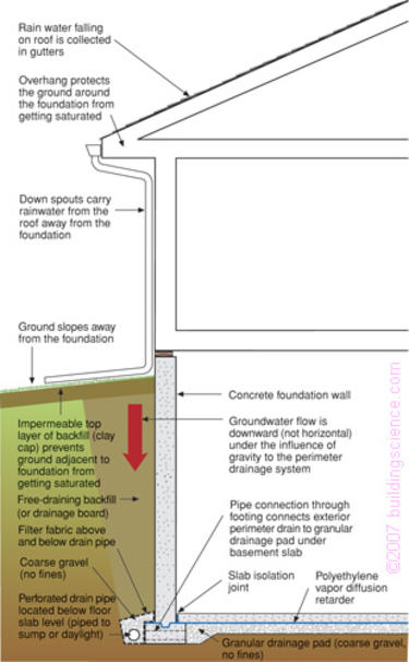
A free draining layer of backfill material or some other provision for drainage such as a drainage board or drainage mat should be used to direct penetrating groundwater downward to a perimeter drain. The perimeter drain should be located exterior to the foundation and wrapped completely in a geotextile (“filter fabric”). A crushed stone drainage layer under the basement slab should be connected through the footings to the perimeter drain to provide drainage redundancy and to provide a temporary reservoir for high groundwater loading during downpours if sump pumps fail during electrical outages (if gravity drainage to daylight is not possible).
Groundwater exists in more than the free-flowing liquid state. Water from wet soil can also wick (capillary flow) and move by diffusion through the soil and the materials used to make basements. Therefore the basement wall should be damp-proofed and vapor-proofed on the exterior and a capillary break installed over the top of the footing to control “rising damp.” Damp-proofing and vapor-proofing in these locations is often provided by a fluid applied coating of bitumen. In the past, capillary breaks over footings were not common. They were not needed when basement perimeter walls were uninsulated and unfinished on the interior, because these conditions permitted inward drying of the migrating moisture. For finished basements they are an important control mechanism. Without them, moisture constantly migrates through the foundation, and then into the interior insulation layer and interior gypsum board lining.
A capillary break and vapor barrier should be located under concrete basement floor slabs. Crushed stone or coarse gravel acts as an effective capillary break and sheet polyethylene in direct contract with a concrete floor slab acts as an effective vapor barrier. The concrete slab should be sealed to the perimeter basement wall with sealant (the concrete slab becomes the “air barrier” that controls the flow of soil gas into the basement).
The crushed stone drainage layer under the basement concrete slab should be vented to the atmosphere to control soil gas (Figure 3). Atmospheric air pressure changes are on the order of several hundred Pascal’s (an inch of water column) so that the soil gas vent stack is in essence a “pressure relief vent” or “soil gas bypass” to the atmosphere. Perforated pipe should be attached to the vent stack to extend the pressure field under the slab to the foundation perimeter and to the drainage layer outside the walls. Pipe connections through the footing extend the pressure field further to the exterior perimeter drain (as well as providing drainage redundancy as previously noted).
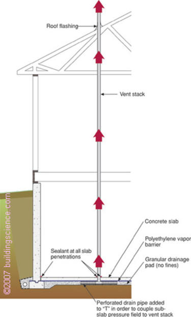
- Sub-slab pressure field coupled to the atmosphere to relieve pressure differences.
- Avoid offsets or elbows in vent stack to maximize air flow.
The traditional approach to basement water control has been to place the barrier and control layers on the outside and then allow drying to the inside. Drainage, damp-proofing or water-proofing and vapor control layers have historically been located on the outside of basement perimeter walls and crushed stone layers and plastic vapor barriers have been located under concrete slabs. The operative principle has been to keep the liquid, vapor, and capillary water out of the structure and locate vapor barriers on the outside – and allow inward drying to the basement space where moisture can be removed by ventilation or dehumidification.
The approach to basement soil gas control should be to allow pressure relief by creating pressure fields under and around basement foundations that are coupled to the atmosphere – intercepting the soil gas before it can enter the structure and providing a bypass or a pathway away from the conditioned space.
Insulating Basements
Comfort and energy costs have lead to the necessity to insulate basements. Heat loss from basements accounts for a significant portion of the total space-conditioning load – upwards of 20 percent (Timusk, 1981). In many jurisdictions, basement insulation is a building code requirement and the trend to more basement insulation is expected to accelerate. Additionally, many homeowners with homes with basements finish the basement area for additional living space. When they do, they typically insulate the perimeter walls. Homes with basements often end up with basement walls that are finished and insulated.
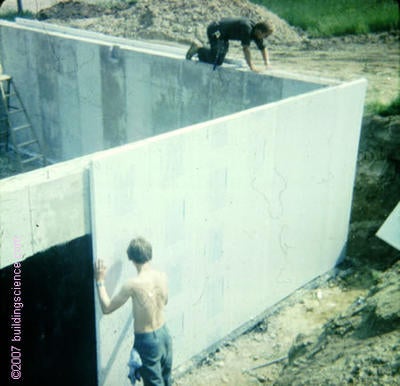
Four generic insulation approaches are possible: insulate on the inside, the outside, the middle or both sides (Figure 4). The most logical location from the building physics perspective is to locate the insulation on the outside as in a commercial institutional wall assembly. By locating the insulation layer outward of the structure and outward of the water control layers the foundation is kept at a constant temperature and the insulation system does not interfere with the inward drying of the assembly. Exterior basement insulation (Photograph 1) is completely compatible with the traditional approach for foundation water control (described above).
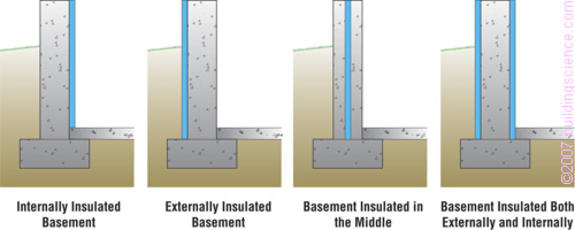
- Interior insulation most common, least expensive, has most moisture problems.
- Exterior insulation best location from physics perspective, has practical problems with protection, thermal bridging and insects.
- Insulation in middle is most expensive approach, has fewest moisture and insect problems, but is the most difficult to construct.
- Insulation on both sides has similar problems to the exterior insulation approach with the additional cost of the interior layer.
Unfortunately, exterior basement insulation can have significant application problems that often make it impractical to employ. The first is the difficulty in protecting the insulation layer during the construction process and subsequently during its useful service life. The cost of a protection layer often is more expensive than the insulation itself. The second is insect control – particularly in the south. Exterior insulation can be an “insect interstate” that provides a direct pathway into the structure. Poisoning the insulation or the soil is often the only viable approach with exterior insulation as barriers (“termite shields”) have proven problematic (Lstiburek, 2004). Third is the problem of thermal bridging when brick veneers are used (Figure 5). There is no known practical cost effective solution to the thermal bridging brick veneer problem when exterior basement insulation is used in residential basements.* The heat loss is so severe as to almost negate the insulation layer (Timusk, 1981).
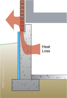
Thermal bridge associated with brick veneer reduces effectiveness of the insulation at top of wall.
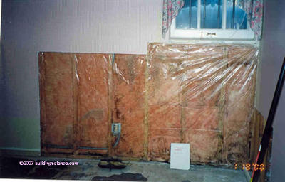
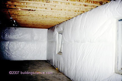
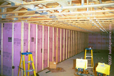
These factors have led to looking at alternative approaches to basement insulation – primarily locating insulation layers on the interior. Unfortunately, locating insulation layers on the interior often conflicts with the traditional approach of foundation water control – namely inward drying. Constructing frame walls, insulating the resulting cavity and covering with an interior plastic vapor barrier is common (Photograph 2) and often leads to odor, mold, decay and corrosion problems (Fugler, 2002; Ellringer, 2002). Also common, and prone to similar problems, is the use of “blanket insulation” often derisively referred to as “the diaper” for the odor problems associated with the approach (Photograph 3).
* The author has tried over 25 years everything from aerated autoclaved concrete in the first course of brick, to supporting the brick veneer on a steel shelf angle, to a separate foundation supporting only the brick veneer, to high density-high compressive strength “highway” foam. He has given up and patiently waits for someone clever to solve the problem in such a simple and elegant manner as to be joyously embarrassing to the author.
- Ideal location from the physics perspective.
- Practical problems with protection, insect control and thermal bridging of brick veneers.
- Plastic vapor barrier prevents inward drying.
- Common outcome are odor, mold, decay and corrosion problems.
- Plastic film on interior of blanket insulation prevents inward drying.
Problems that interior insulation systems have to overcome are numerous:
- Groundwater entry (Figure 6)
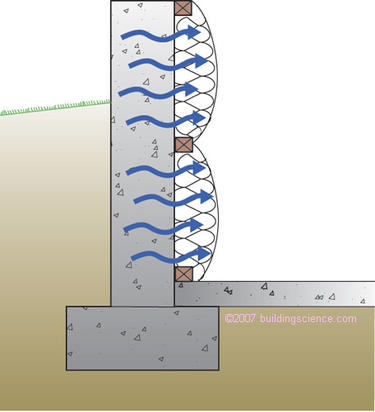
- Moisture of construction (Figure 7)
- Capillary rise through footing (Figure 8)
- Condensation from interior air leakage (Figure 9)
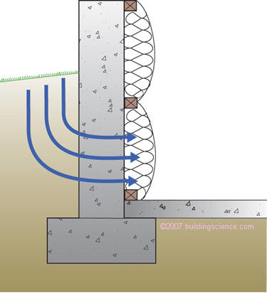
- Interior insulation layer is typically water sensitive and prevents inward drying.
- Interior insulation layer is typically water sensitive and prevents inward drying.
- Several thousand pounds of water in freshly placed concrete attempts to dry inward.
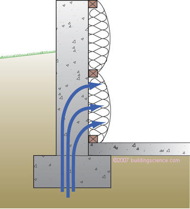
- Interior insulation layer is typically water sensitive and prevents inward drying.
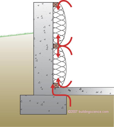
- Interior insulation layer is typically not airtight and does not prevent interior air from condensing on concrete foundation wall.
- Soil gas often enters assembly at concrete slab-perimeter wall interface leading to condensation.
Most interior insulation systems are constructed with moisture sensitive materials (i.e. fiberglass batts or blankets) and are unable to tolerate even minor groundwater leakage, therefore requiring builders to be “perfect” in controlling groundwater – an impossible requirement. These systems also can prevent inward drying (i.e. when they are covered with plastic vapor barriers). This is an issue with moisture of construction, capillary rise and ground water leakage.
Simply leaving off plastic or other low permeance vapor barriers will not avoid problems, because interior water vapor will migrate outward. Then it will condense on the interior surface of the foundation wall providing moisture for mold growth and other problems.
An even greater moisture problem can be created by air leakage from the interior. As most interior insulation systems are not airtight they allow interior air to access the interior surfaces of the perimeter concrete foundation.
The structural elements of below grade walls are cold (concrete is in direct contact with the ground) – especially when insulated on the interior. The main problem with below grade walls comes during the summer when warm moist air comes in contact with basement cold surfaces that are below the dewpoint of the interior air. Of particular concern are rim joist areas – which are cold not only during the summer but also during the winter (Goldberg & Huelman, 2000).
Basement walls should be insulated with non-water sensitive insulation that prevents interior air from contacting cold basement surfaces – the concrete structural elements and the rim joist framing. The best insulations to use are foam based and should allow the foundation wall assembly to dry inwards. The foam insulation layer should generally be vapor semi impermeable (greater than 0.1 perm), vapor semi permeable (greater than 1.0 perm) or vapor permeable (greater than 10 perm) (Lstiburek, 2004). The greater the permeance the greater the inward drying and therefore the lower the risk of excessive moisture accumulation. However, in cold climates or buildings with high interior relative humidity during cold weather, the upper portion of a basement wall may become cold enough that a vapour permeable insulation will allow a damaging amount of outward diffusion during cold weather. A semi-permeable vapour retarder or foam or a supplemental layer exterior insulation can be used in these situations.
In all cases, a capillary break should be installed on the top of the footing between the footing and the perimeter foundation wall to control “rising damp.” No interior vapor barriers should be installed in order to permit inward drying.
Up to two inches of unfaced extruded polystyrene (R-10), four inches of unfaced expanded polystyrene (R-15), three inches of closed cell medium density spray polyurethane foam (R-18) and ten inches of open cell low density spray foam (R-35) meet these permeability requirements.
The most cost effective approach involves a combination of rigid insulation and an insulated frame wall assembly (Photograph 4, Figure 10 and Figure 11). Spray foam – either closed cell or open cell – provides the least risky interior insulation assemblies from the perspective of installation simplicity, water insensitivity and ease of drying (Figure 12).
- Rigid insulation continuous behind wood frame wall.
- Rigid insulation is vapor semi-impermeable or vapor semi-permeable (foil facing or plastic facing not present).
- Wood frame wall cavity to be insulated with unfaced fiberglass or damp spray cellulose.
- No vapor barrier installed.
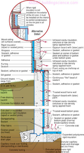
- Cold concrete foundation wall must be protected from interior moisture-laden air in summer and winter.
- Rigid insulation continuous behind wood frame wall.
- Rigid insulation is vapor semi-impermeable or vapor semi-permeable (foil facing or plastic facing not present).
- Wood frame wall cavity to be insulated with unfaced fiberglass or damp spray cellulose.
- No interior vapor barrier installed.
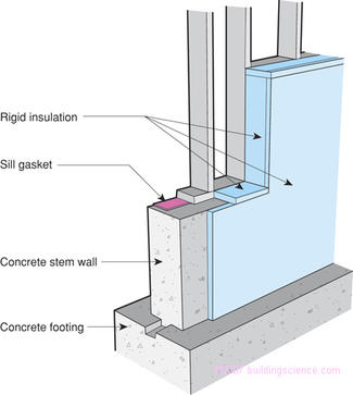
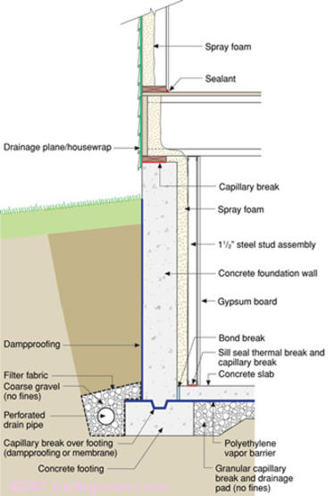
Figure 11: Rigid Insulation Wraps Exposed Concrete
- Cold concrete foundation wall must be protected from interior moisture-laden air in summer and winter.
- Rim joist assembly must be insulated with air impermeable insulation.
- Rigid insulation completely wraps exposed concrete preventing interior air from contacting potential concrete condensing surface.
- Rigid insulation is vapor semi-impermeable or vapor semi-permeable (foil facing or plastic facing not present).
- Least risky interior insulation approach.
- Cold concrete foundation wall must be protected from interior moisture-laden air in summer and winter.
- Rim joist assembly must be insulated with air impermeable insulation.
- Interior air cannot access concrete condensing surface or rim joist condensing surface due to spray foam layer.
- Spray foam insulation layer is vapor semi-permeable permitting inward drying.
- Spray foam must be covered with fire/ignition barrier.
Basement floor slabs are best insulated underneath with rigid insulation: both extruded or expanded polystyrene have been widely used with success. The radiant barrier bubble insulations on the market are not recommended as they do not provide sufficient insulation or value. Although the energy savings of sub-slab insulation are not as significant as basement wall insulation, such insulation is critical for radiantly heated basement slabs and do offer a significant improvement in comfort and moisture damage resistance (including against summertime condensation).
A sheet polyethylene vapor barrier should be located over the rigid insulation and in direct contact with the concrete slab. A sand layer should never be installed between the sheet polyethylene vapor barrier and the concrete slab. Sand layers located between the slab and the vapor barrier can become saturated with water, which are then unable to dry downwards through the vapor barrier. In this scenario, only upward drying through the slab is possible which typically results in damaged interior floor finishes (Lstiburek, 2002).
Impermeable interior floor finishes such as vinyl floor coverings should also be avoided – as should impermeable interior basement wall finishes such as oil (alkyd) paints and vinyl wall coverings. These impermeable layers inhibit inward drying and typically lead to mold growth and other moisture problems.
The floor finishes and interior finishes on the lower parts of basement walls (interior and enclosure walls) should be chosen with a consideration for the possibility of flooding from leaky appliances, failed plumbing, overflowing sinks, or exterior surface flooding.
Conclusions
Liquid and capillary water should be kept out of the basement assembly using surface drainage, below grade drainage layers, perimeter drains, and capillary breaks. Vapor barriers should be located on the exterior of basement assemblies allowing inward drying to the basement space where moisture can be removed by ventilation or dehumidification.
Soil gas should be controlled by locating pressure fields under and around basement foundations that are coupled to the atmosphere – intercepting the soil gas before it can enter the structure and providing a bypass or a pathway away from the conditioned space.
If basement wall systems are designed and constructed to dry to the interior – regardless of where insulation layers are located – interior vapor barriers must be avoided. This precludes interior polyethylene vapor barriers installed over interior frame wall assemblies or any impermeable interior wall finish such as vinyl wall coverings or oil/alkyd/epoxy paint systems.
If an interior insulation layer is used the indoor air should be prevented from reaching the concrete structural wall assembly or rim joist assembly (unless insulated on the exterior) in any significant volume. Rigid foam systems or spray-applied foams are recommended for this purpose, because they allow drying, are not sensitive to moisture damage, and do not support mold growth – essential characteristics for all materials which contact the basement wall and basement floor slab.
References
Ellringer, P.; “Minnesota Mold Busting”, Home Energy Magazine, June 2002.
Fugler, D.; “Dry Notes From The Underground”, Home Energy Magazine, April 2002.
Goldberg, L. and P. Huelman; “Rim Joist Report and Foundation Insulation Project Final Report”, Minnesota Department of Commerce, University of Minnesota, June 2000.
Lstiburek, J.; Builders Guide to Cold Climates, Building Science Press, September 2001.
Lstiburek, J.; “Investigating and Diagnosing Moisture Problems”, ASHRAE Journal, December 2002.
Lstiburek, J.; “Understanding Vapor Barriers”, ASHRAE Journal, August 2004.
Timusk, J.; “Insulation Retrofit of Masonry Basements”, Department of Civil Engineering, University of Toronto, 1981.