Spray polyurethane foam (SPF), the high-density stuff,1 is the only product (so far) that can perform all of the functions of the principal control layers of the “Perfect Wall.”2 The functions are water control, air control, vapor control, and thermal control.
Figure 1 and Photograph 1 illustrate the configuration. Pretty simple and straightforward, eh? Wrong.3 Simple and straightforward only if you have no windows, no doors, no penetrations, only use brick cladding and only use brick cladding on one-story buildings, and if it is not too cold when you apply it, and if it is not too windy when you spray it.4 In any event, I still like the stuff despite some of this stuff because the stuff can do stuff no other stuff can do.
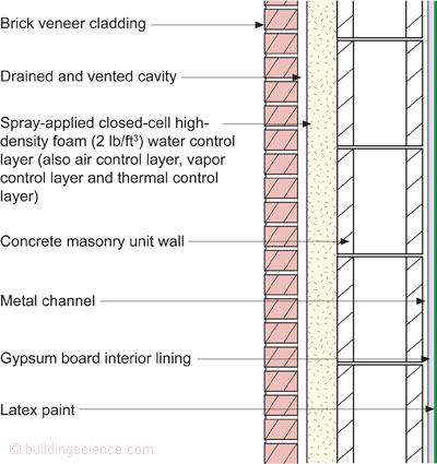
Figure 1: Perfect Wall Configuration for SPF—Spray-applied closed-cell high-density foam is the water control layer, the air control layer, the vapor control layer and the thermal control layer.
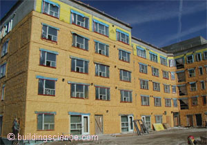
Photograph 1: The Perfect Wall?
As with most materials and systems, you must work your way through the weaknesses and maximize the strengths. Let’s start with the easy stuff first and work our way through to the more difficult stuff.
Windows first. Absolutely, positively do not, and I repeat, do not spray the SPF to the windows. Are you crazy? How are you ever going to get them out? You will have to hack them out. Ask me how I know. Think windows don’t break? Think they don’t leak? Think we can reduce the deficit without reducing spending and controlling entitlements? Dream on. The best play is to provide a transition assembly between the glazing systems and the wall assembly. Use the concept of an extended “buck” (Figures 2a and 2b for masonry backup walls and Figures 3a and 3b for steel stud backup walls). Notice the plywood “lip” and the use of a liquid-applied flashing membrane to provide a drained opening (an under window “gutter” that directs water to the outside face of the SPF should the window assembly leak). This approach allows standard window installation ap¬proaches to be used. Also notice how the membrane extends around the opening onto the face of the masonry backup wall or on the face of the sheathing over the steel stud backup wall. This is called “raccooning” because of the eyes of a raccoon, not when your mascara runs or periorbital ecchymosis. With this approach, the windows can be installed either before or after the application of the SPF.
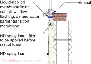
Figure 2a: Masonry Wall Sill Detail—Wood buck with plywood lip creates under window gutter. Note the foam “filet” “picture-framing” the opening.
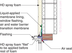
Figure 2b: Masonry Wall Head Detail—The foam “filet” is sprayed first to prevent the head flash¬ing from being pulled upward leading to a negative slope.

Figure 3a: Steel Frame Wall Sill Detail—Don’t forget the importance of the foam “filet.”
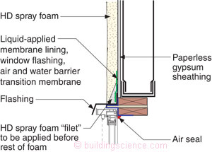
Figure 3b: Steel Frame Wall Head Detail—A negative slope is not a positive development.
Now for the secret double probation stuff that no one tells you about. Notice in the images the use of “gray” shading to “define” something called a spray foam “filet”? Upon application, SPF tends to pull away from some surfaces; shrinkage is a term sometimes used. This is a problem at openings. To prevent a gap from opening up between the edge of the extended buck and the SPF, the perimeter of the opening is “picture-framed” with SPF in a “filet” shape/geometry. Then the field of the wall is sprayed. It’s easy and it works, but you have to know that you have to do it. This is a big deal at the tops of windows because if you don’t do it the flashings can be pulled upward, resulting in a negative slope on the flashings. If you get a negative slope on a flashing, it will ruin your day. In fact, all flashing should have the “filet” treatment first before the field of the wall gets sprayed.
Memo to architects: treat door openings the same way. Sort of. Don’t forget the head flashings, and don’t pretend that the masonry jamb trim can be used as part of the water control. Take the trim off the freaking doors first, OK? Install the “trim less” doorframes. Water manage the opening. Then install the trim.
Concrete frame buildings shrink over time (Figure 4). Yup. They get shorter. Structural engineers don’t use the word “shrink” because that would make things understandable to non-structural engi¬neers, and we can’t have that. Sometimes the word “creep” is used; sometimes the phrase “frame-shortening” is used. Sometimes it is just kept a secret among the structural engineers.
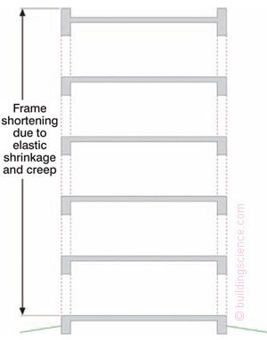
Figure 4: Frame Shortening—How much and how soon? More than you think and a decade or two. Around an inch or two over 20 stories, but this is very variable.
This can be a lot of fun when you use brick because sometimes the brick expands when its moisture content equilibrates after it comes out of the kiln, and it does this equilibration while it is on the building. When the frame gets shorter, and the cladding gets taller, things get stressed, especially the structural engineer. Now, structural engineers are incredibly clever and resourceful folks. This problem was solved long ago with the use of “relieving angles”5 and “soft” joints. Check out the “soft” joints in Figures 5 and 6a and the concept of the “nested” track in Figure 6b. I told you they were clever. The relieving angle is shown in Figure 7. Also note how the relieving angle is held away from the wall on brackets (or “stand-offs”) to control thermal bridging.6 See, they are being clever again.
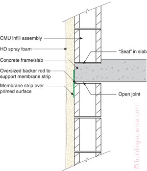
Figure 5: Masonry Soft Joint—Notice the gap. Beauty, eh? Also, note the “seat” in the slab to deal with rainwater leakage. This is stolen from our contractor friends in Florida who know all about masonry walls and rain.
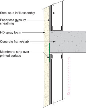
Figure 6a: Steel Frame Soft Joint—Don’t forget the “nested” track for the steel frame (check out Figure 6b).
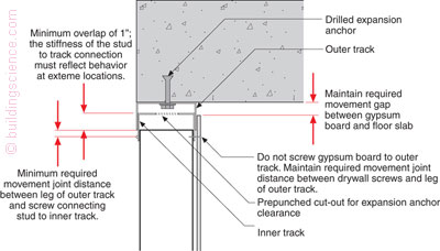
Figure 6b: Nested Track—Clever structural engineering. If it moves, let it move. It is a Zen thing. Hey, when you get old, you will shrink too.
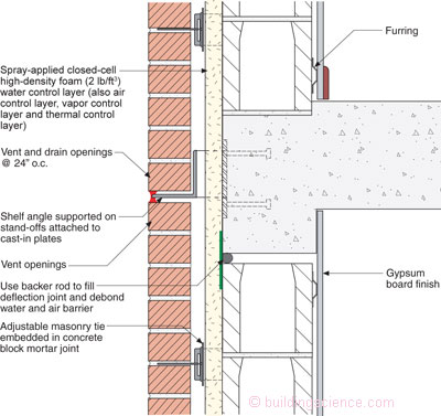
Figure 7: Stand-Offs For Relieving Angle—This is a beautiful thing. Thermal bridging is controlled, as well as frame shortening along with water, air and vapor.
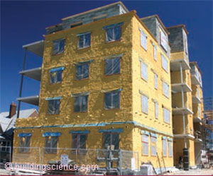
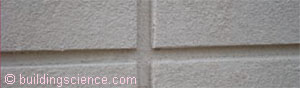
So why is brick relatively easy with SPF? It’s the brick ties and the air gap behind the brick and those relieving/shelf angles. We do that stuff with normal brick walls even without SPF. Nothing new or weird there. Here is the issue. SPF does not go on completely smooth and flat and of uniform thickness. The air gap behind the brick makes this problem a non-problem and we have lots of brick ties that work with large air spaces. Check out Photographs 2, 3 and 4. Looks good and is easy. But, what if you don’t want brick?
Photograph 2: SPF Applied—Step one.
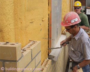
Photograph 3: Brick Installed—Step two.
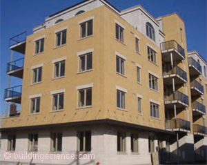
Photograph 4: Finished Building—Step three.
Attaching panel cladding through SPF is not that straightforward, although it should be. Once you “get it” you will see that it is not a problem either. But sometimes the obvious is only the obvious when someone points out that it is obvious.
The really easy part of attaching panel claddings is you need straight “thingies” that go up and down or from side to side or both. Check out Photographs 5, 6, 7 and 8. The difficulty comes from how you attach the straight “thingies” without causing huge thermal bridges.
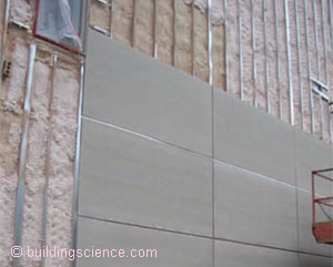
Photograph 5: Vertical channels for panel cladding.
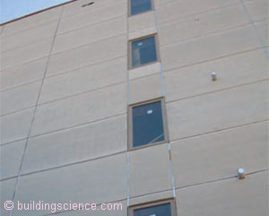
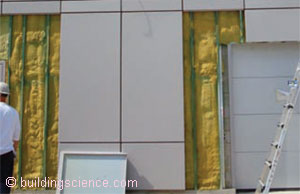
Photograph 6: Panel Cladding—Fiber cement panels attached to metal channels.
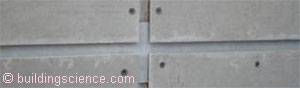
Photograph 7: Panel Cladding Joint Treatment—Joints do not need to be watertight or airtight as cladding system is back-ventilated and drained.
Photograph 8: Finished panel cladding joint.
The not-so-good way of doing the straight “thingies” is shown in Photograph 9 and Figure 8a. The straight “thingy” is a metal Z-bar that is screwed through paperless gypsum sheathing directly into steel studs. It is easy but you lose around 50% of the thermal performance of the SPF due to the conductivity of the metal Z-bar. The only good news is that the Z-bars are much farther apart than typical steel studs, but this is still not good.
Photograph 9: Z-Bar attachment for panel cladding.
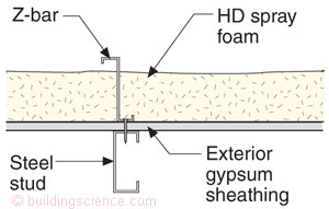
Figure 8a: Z-Bar Thermal Bridge—Ultraconservative structurally and not particularly energy efficient. Come on, grow a set and get with the program.
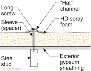
Figure 8b: Hat Channel Stand-Off—Now we are talking.
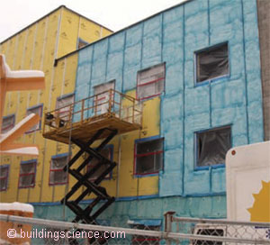
This next part freaks folks out although it should not. The easy fix to the conductivity problem of the metal Z-bar is to use stand-offs, which are basically long screws in a “spacer sleeve” (Figure 8b). And, it is even better when the straight “thingy” is non-conductive, like wood (Figure 9). Check out Photographs 10, 11 and 12 for commercial assemblies and Photograph 13 for a residential exterior retrofit.
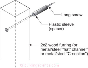
Figure 9: Wood Furring Stand-Off—Non-conductive “thingy.”
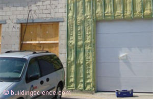
Photograph 10: Light Industrial Strip Mall—Masonry wall insulated on the exterior with spray foam. Note the treated wood 2x2 furring on screw offsets.
Photograph 11: Steel Panel Cladding—Steel panels installed onto wood 2x2 wood furring embedded in spray foam on masonry wall enclosure for a light-industrial strip mall.
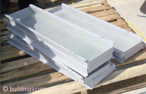
Photograph 12: Steel Panels—These panels do not need to be watertight or airtight.
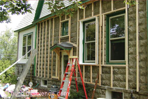
Photograph 13: Wood Frame Off-Set Residential Retrofit—Pretty neat, eh? My friend Peter Yost’s house in Vermont prior to installation of SPF.
The “freak-out” part is the structural strength of the cladding attachment. How can you hang those “thingies” so far away from the wall on long screws? The compressive strength of the SPF makes it work. The issue is screw bending—the “bending moment” of the screw. Here comes the obvious part. For the screw to bend it has to rotate inward into the wall. For it to rotate inward into the wall, the “thingy” has to rotate with it. The “thingy” pushes against the SPF and the SPF pushes back. The compressive strength of the SPF resists the rotation inward of the “thingy.” Check out Figures 10 and 11. Structurally, this can easily be calculated7 as a “truss.” The “thingy” frames are real flimsy until the SPF is applied. The foam expands outward and bonds to the frames. Then things are unbelievably stiff.
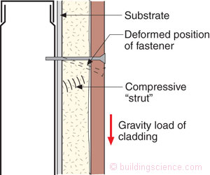
Figure 10: Inward Rotation Resistance—For the screw to bend, it must rotate inward into the wall. For it to rotate inward into the wall, the “thingy” has to rotate with it. The “thingy” pushes against the SPF and the SPF pushes back. The compressive strength of the SPF resists the rotation inward of the “thingy.”
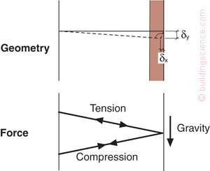
Now, despite the ease of calculation, structural engineers, and engineers in general, like “tests.” We have done lots of tests. We have found that you can pretty much hang an SUV off the wall using screw stand-offs and SPF. In fact, we have found the same thing with extruded polystyrene board insulation and isocyanurate board insulation. The short answer is that a “truss analogy,” as a basis for calculation, provides a conservative result for all of these insulations. If you want a less conservative answer, use finite element analysis or do your own tests. I bet that conservative wins.
Footnotes:
We are talking the 2 lb/ft3 (32 kg/m3) stuff, not the low-density 0.5 lb/ft3 (8 kg/m3) stuff or the “new” medium-density 1 lb/ft3 (16 kg/m3) stuff. In reality, the 2 lb/ft3 (32 kg/m3) high-density stuff is not really high-density stuff at all. There is much higher density SPF used in industrial applications, but we folks in the construction industry do not care about industrial applications, so the 2 lb/ft3 (32 kg/m3) stuff is high-density to us. It is not high-density stuff to chemical engineers and to the chemical companies who make the chemicals that comprise the stuff and provide the formulations to blow the stuff, so confusion reigns. And, that is good because obviously the world needs more confusion. It gets even better. We also call the 2 lb/ft3 (32 kg/m3) stuff “closed-cell” spray-applied foam and the 0.5 lb/ft3 (8 kg/m3) stuff “open-cell.” We don’t quite have a “cell” name for the medium-density stuff yet, and if I had my way we would never get one. In any event, the “cell” stuff relates to vapor control. The 2 lb/ft3 (32 kg/m3) stuff is around 3 perms per inch of thickness, and the 0.5 lb/ft3 (8 kg/m3) stuff is around 50 perms per inch of thickness. The difference is a big deal. The 1 lb/ft3 (16 kg/m3) stuff is around 15 perms per inch of thickness. There is more. The 2 lb/ft3 (32 kg/m3) stuff has a thermal resistance (R-value) of 6.5 per inch, the 0.5 lb/ft3 (8 kg/m3) stuff is around 3.5 per inch, and the 1 lb/ft3 (16 kg/m3) stuff is around 4 per inch.
Do you have any idea how difficult it is to get this “stuff” off a car parked downwind? The word “stuff” is not the word I wanted to use in this footnote rant. For the first job I specified SPF on in 1979, I made the mistake of driving my nice new shiny red Camero to the site. Lucky for me the new wax job on my car made it only irritating to me. But not for the framer’s car. Guess who had to clean his car?
See Footnote 3 above.
Lots of folks call them “shelf angles,” but I prefer the term “relieving angle” because it better describes their function. It’s that terminology thing with me again. Can’t help it.
See BSI-005: A Bridge Too Far (“Clint Eastwood Thermodynamics” in Figure 2, Photographs 8a and 8b).
Although structural engineers are clever folks, they hate this part because they have to do something they have not done since they graduated—something called a “calculation.” I know, I know, it is easier to look things up in a table, but we don’t have tables yet. They are coming, probably in the next Code cycle. So, in the meanwhile, relax and calculate.