It is a beautiful building. Quite stunning actually. It is an embodiment of everything that is right and wrong with architecture.1 An orgy of glass and concrete. It is a thermodynamic obscenity while it takes your breath away. An 82-story heat exchanger in the heart of Chicago2 (Photograph 1a, b, c, d, e, f, g).
Aqua-Naught*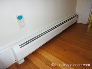
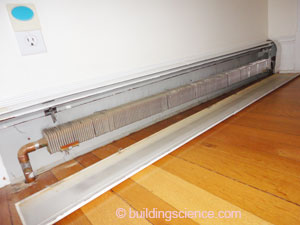
Photograph 1a (left): Baseboard Radiator; Photograph 1b (right): Liquid Gas Heat Exchanger
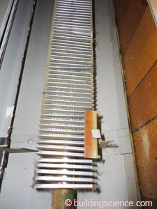
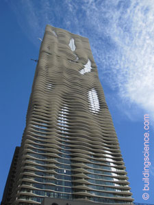
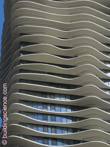
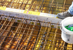
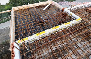
Photograph 1c (left): Extended Finned Surface – Aluminum; Photograph 1d (middle): Extended Finned Surface – Concrete; Photograph 1e (right): Aqua Tower Balcony’s
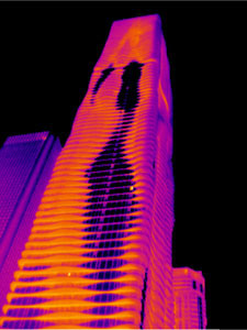
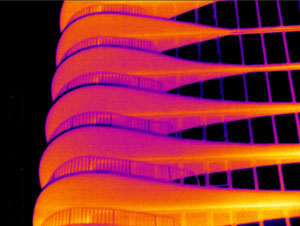
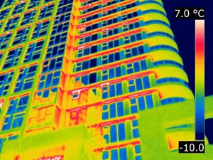
Photograph 1f (left): Infra-red of Aqua Tower - Image courtesy of Dave Robley, Thermographer, Fluke Corp and Michael Stuart, L3 TI/IRT, Fluke Corp.; Photograph 1g (right): Infra-red of Aqua Tower Balcony - Image courtesy of Dave Robley, Thermographer, Fluke Corp and Michael Stuart, L3 TI/IRT, Fluke Corp.
Could it have been constructed differently without the thermal bridges? Without changing the appearance? Sure. It could have been an example of efficiency not just iconic architecture. And that would have been a beautiful thing. With off the shelf stuff no less. How about a true R-5 curtain wall between thermally broken cantilevered slabs? Check out Figure 1 and Photograph 2. Available right here in the good ole US of A. Also, apparently in Serbia (Photograph 3) and pretty much anywhere folks care. Triple-glazed gas-filled curtain walls have been around for a while. Nothing magical there. The thermal breaks have also been around for a while. Mostly in Europe, and in Canada, which seems like Europe lately.3
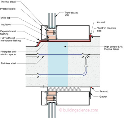
Figure 1: Section At Balcony Glazing Interface – Take a high performance curtainwall and couple it with a high density expanded polystyrene thermal break and some basic slab water control and you have a beautiful thing. No reason why this could not have been done. The argument against is cost of course. But in Chicago in a fabulous building like this? The stunning architecture alone ups the value of the building way beyond the cost of the good glass and the thermal breaks. Hey, I like this building. I am just dreaming of what could have also been…
Photograph 2: Pre-manufactured Thermal Break – High density graphite enhanced expanded polystyrene. Note the reinforcing rods penetrating the foam are stainless steel not carbon steel. Stainless steel has less than half the thermal conductivity of carbon steel. Neat, eh? Image courtesy of Schoeck Canada, Inc.
Photograph 3: Belgrade Balcony – Nice view of the Danube River from a thermally broken balcony. OK, the river is out there somewhere. I have not been to Serbia recently, but apparently they can afford more efficiency than Chicago. It can’t be the climate because Chicago is much colder in the winter. The real estate values must be really something in Belgrade compared to Chicago. Good thing in Chicago we have green roofs. Don’t seem to be many of those in Belgrade either. Priorities are important. The R-value of dirt apparently does not impress Serbs. Image courtesy of Beodom, Inc., Belgrade, Serbia
The Aqua Building is not an exception. Most buildings are like this. Thermal bridges galore (Photograph 4). It is a big deal. The good news is folks are beginning to get it (ASHRAE 90.1) and great work is being done on the research side.4 The bad news is that although we know this stuff it is not getting used. It seems to me that folks just are not serious about energy. This is an architectural problem. This is an architectural detailing problem. This is an architectural detailing problem that involves structural engineering. To deal with this is going to require collaboration between architects and structural engineers. Serious collaboration.
Photograph 4: Toronto At Night – Red is not good…
Too often structural decisions are made in isolation from the energy impacts. It is not that the structural engineer does not care. Amazing things can be done. No one asks. Time to ask. Time to get great things from your structural engineer.
Balconies are a big deal and everyone knows that. But relieving angles can be an even bigger deal. They go completely around a building and sometimes occur at every floor. Balconies rarely do…previous exception noted. The good news is that we know how to deal with relieving angles. The bad news is that we often do not. Sound familiar?
The best way to deal with relieving angles is to hang them off of the building with a “stand-off” (Figure 2) and then spread them out every second or third floor. This allows your insulation to run past the angle. Presto, continuous insulation (Figure 3). The stand-off’s can be welded to plates cast into slabs or welded to structural steel supports (Photograph 5). Amazing as it seems to civilians and other mere mortals, The Architect obsesses over the location of the relieving angle. It just can’t be anywhere. It has to look good wherever it is. Sometimes it has to line up over the heads of windows for reasons that escape me, a mere mortal, so we have to ask the structural engineer to be clever (Photograph 6). See, all you have to do is ask.
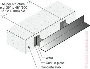
Figure 2: Relieving Angles - Hang them off of the building with a “stand-off”. This allows your insulation to run past the angle.
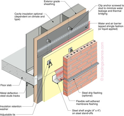
Figure 3: Continuous Insulation - Get used to this. If you are serious about energy this becomes standard practice.
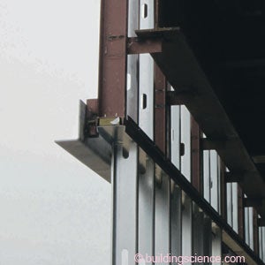
Photograph 5: Stand-Off - Can be welded to plates cast into slabs or welded to structural
steel supports.

Photograph 6: Relieving Angle Line Up – Notice how the relieving angle lines up with the top of the window bringing joy to The Architect. Clever, elegant and simple structural engineering. Hope the structural engineer got lunch out of this one.
What if I do not like brick? Great, no relieving angles. How do I do panels? And how do I do panels “conservatively” if don’t buy into all that other stuff you have talked about. OK, OK, OK. Check out Figure 4. Although the structural design required for thin stainless angles and long galvanized L-rails is simple, engineers normally are designing for loads of thousands of pounds (kips) and the hundred pound loads involved here are unfamiliar and sometimes scary.
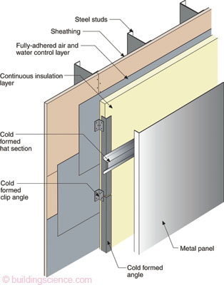
Figure 4: Clip and Rail – Minimum thermal bridging to support metal panels, fiber cement panels and composite panels.
We also have to deal with the thermal bridges associated with windows. For reasons that are unclear to me, where windows are concerned we don’t call it a thermal bridge, we call it “flanking” losses. Flanking losses are losses around the window often through the buck or through the structure components the wall is installed in. Whatever. Bottom line is that you need to line up the thermal control layer in the window unit (a.k.a. “thermal break”) with the continuous insulation you are now required to install on the exterior of the wall. That often means pushing your window outboard and hanging it in mid-air, sort of. Gotta talk to the structural engineer again. Magic will happen again. Check out Photograph 7. Now you have to detail the water control and air control and thermal control layers (Figure 5). Or check out Figure 6 and Figure 7 – lots of possibilities.
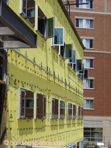
Photograph 7: A Little Bit of Everything - Relieving angles on stand-offs and bumped out windows. Nice. Wonder if there are any LEED points for this? Yeah, probably not.
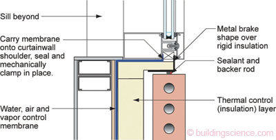
Figure 5: Plan View Alignment - Thermal control of the window frame and IGU lines up with the thermal control layer of the wall to control thermal flanking.
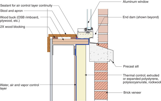
Figure 6: Vertical Alignment – Thermal control of the window frame and IGU lines up with the thermal control layer of the wall to control thermal flanking.
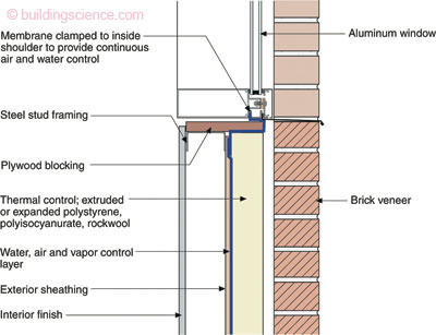
Figure 7: More Vertical Alignment – Thermal control of the window frame and IGU lines up with the thermal control layer of the wall to control thermal flanking.
Photograph 7 has everything. Relieving angles on stand-offs and bumped out windows. Nice. Wonder if there are any LEED points for this? Yeah, probably not.
The best thing to do is to take your structural engineer to lunch and discuss relieving angles, window attachment and balcony thermal breaks. Enjoy a nice moment with your engineer…
Footnotes:
Chicago architect Jeanne Gang (Studio Gang Architects) being interviewed on NPR’s All Things Considered by Melissa Block after being named a MacArthur Foundation Fellow discussing the Aqua Tower: “The strongest force yet you’re going to receive on a tall building is the lateral pressures from the wind. So, because we wanted people to enjoy the outdoors and be able to step outside even on the tallest floor – varying the slab edges the way that we did helps confuse the wind…”
One of my friends, who is acalm, gentle, an architect, someone who gives everyone the benefit of the doubt, someone who is always telling me to put a cork in it, but in a nice way, who I can’t mention by name, went and called Studio Gang Architects and asked a simple question: “Where is the insulation? This is a LEED building? Where is the insulation?” The answer took his breath away: “We have R-11 radiant barrier paint on the projecting slabs…”
What is it with the kids rioting in Montreal? Greece I understand. But Montreal? Apparently they do not understand the Second Law of Thermodynamics: “You can’t get your money for nothing and your chicks for free…”
ASHRAE is on the ball. A great ASHRAE Report No. 5085243.01 – Thermal Performance of Building Envelope Details for Mid and High Rise Buildings (1365-RP) addresses this. This was done for TC 4.4 Building Materials and Building Envelope Performance by Mark Lawton’s team at Morrison Hershield. Well done folks. Very well done indeed.