Gypsum board drywall is, itself, a suitable air barrier material. The taping of drywall seams results in a plane of airtightness at the field of the wall. However, several steps must be taken to use this material property to create a continuous and complete air barrier system.
Drywall Assembly Perimeter
Air barrier continuity at the perimeter of drywall assemblies is achieved by sealing the edges of the drywall to solid framing materials. This requires a continuous bead of sealant along:
- all exterior wall bottom and top plates,
- all top plates at insulated ceilings,
- rough opening perimeters, and
- both sides of the first interior stud of partition walls.
The air seal at the partition wall intersection is shown in greater detail below.
Penetrations of Drywall Assemblies
Typical penetrations in exterior wall and ceiling drywall assemblies include electric penetrations—electric boxes and recessed fixtures. Electric boxes can be made air tight by caulking or sealing all openings in the box (including around wire penetrations) and by sealing the face of the box to the drywall. Specially designed airtight electric boxes with flexible boot seals at wire penetrations and a gasketed flange at the face can also provide air barrier continuity.
Recessed ceiling fixtures in insulated ceiling should be both insulation contact (“IC”)- and air tight rated. The housing of the recessed fixture should also be sealed (with caulk or an effective gasket) to the ceiling gypsum board.
Structural Framing Air Barrier Transitions
Obviously, drywall cannot provide an air barrier where it is absent. The diagrams below show how the air barrier continuity is maintained through the framing at rim joist/band joist areas. These measures form a necessary complement to drywall sealing in the airtight drywall approach. Refer to other Information Sheets for air sealing details at other common conditions. The resources listed below also illustrate air sealing details and provide further discussion.
Air Barriers—Airtight Drywall Approach Details
Figure 1
Sealing Perimeter of Drywall Assemblies
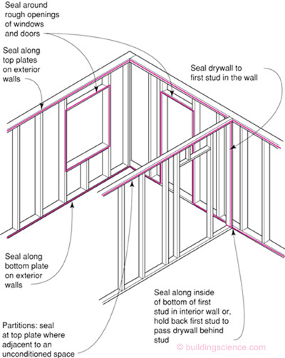
Figure 2
Airtight Drywall Approach—Interior Air Barrier Using Drywall and Framing
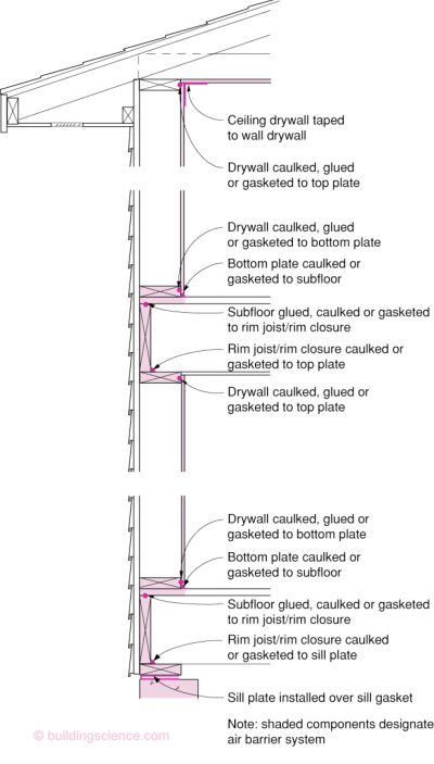
Figure 3
Electrical Box Penetrations
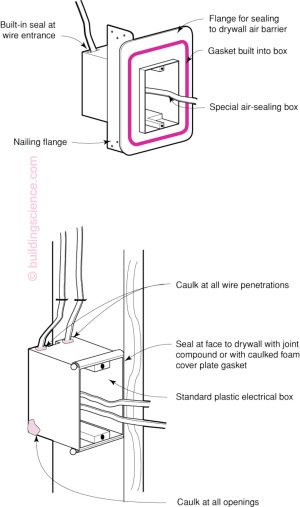
Figure 4
Air Sealing at Partition
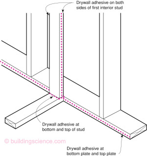
- Adhesive at bottom and top of partition stud allows air barrier to transition uninterrupted to other side of partition
- Penetrations through first partition stud must also be sealed
Figure 5
Top Plate with Unconditioned Space Above
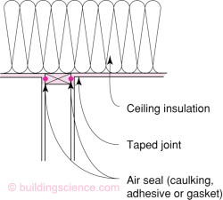
- Penetrations through top plate must also be sealed
Figure 6
Intersection of Floor Joists and Exterior Wall
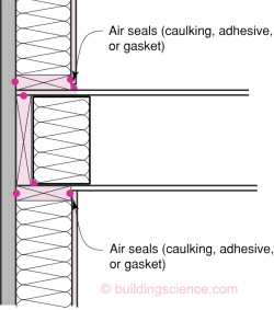
- Drywall sealed to top and bottom plates
- Bottom plate sealed to subfloor
- Subfloor sealed to rim closure board
- Rim closure board sealed to top plate
Figure 7
Recessed Fixture in Insulated Ceiling
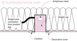
- Fixture labeled IC-rated and airtight as determined by ASTM E-283 air leakage test
- Housing (not decorative trim piece) sealed to ceiling with caulk or gasket
Figure 8
Air Barrier Continuity at Rim Joist/Band Joist
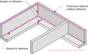
- Continuous fillet bead applied at bottom of rim closure board
- Continuous bead of adhesive applied to top of rim closure board
- Sealant applied at all butt joints in rim closure board and sill plate/top plate
- Spray foam may also be used to seal between the sill/top plate, rim/band joist, and floor deck. Note that joints in the sill/top plate may not be sealed by the foam application.