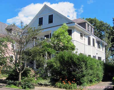
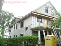
This triple decker, built in 1907, was purchased in 2006 by the current owner who occupies one of the units along with her husband and their toddler. As an initial step towards improving the energy efficiency and combustion safety of the building, the owner replaced the existing old boiler with a cogeneration system that includes a closed combustion gas boiler to provide heating and hot water along with bonus electricity as a by-product.
In 2010, the owner began working with Byggmeister and DEAP Energy Group to develop plans for making the additional improvements needed. The structure of the building was sound and the existing slate roof was in good condition. However the siding was worn and in need of paint, the windows were vinyl replacement windows which were worn and leaky and the building itself was leaky. The resulting plan was for a comprehensive energy efficiency retrofit project and participation in the National Grid DER Pilot program.
The retrofit project included new fiber cement siding installed over exterior insulation, new high performance windows, a conditioned basement, improved insulation at the attic and roof, and improved air tightness. The result is a more durable building with increased comfort for occupants. This was accomplished with minimal disruption to the occupants and without significantly changing the appearance or the character of the building.
Project Team: Byggmeister, Inc., General Contractor; The DEAP Energy Group, DER Design Consultant; Building Science Corporation, Consultant and Technical Support; National Grid, Massachusetts, DER Pilot Program Administrator/Sponsor
Location: Jamaica Plain, Massachusetts
Description: Comprehensive energy efficiency update of 1907 triple decker, 3,885 ft2 above-grade living space, 3-family residence with conditioned basement
Completion Date: July 2011
Estimated Annual Energy Savings: Projected 48% energy use reduction compared to the pre-retrofit conditions
Design
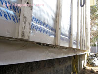
The retrofit strategy for the enclosure of the house was determined by the relative condition and accessibility of the different enclosure components. Since the siding was old and would require on-going maintenance, it was decided to replace it with fiber cement siding. With the siding being removed, it was possible to blow cellulose into the wall cavities from the outside, to apply insulating sheathing over the existing board sheathing, and to create a robust drainage plane behind the new siding.
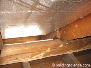
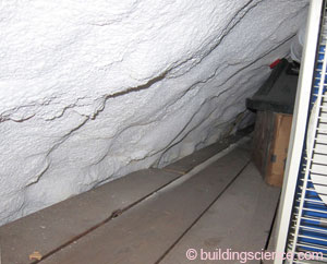
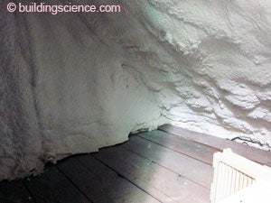
Since the slate roof was in good condition, any improvements to the roof/attic area were restricted to work that could be done from below. This, along with the constraint that the interior ceiling and walls of the 3rd floor unit remain intact, resulted in a hybrid approach to the roof/attic. After installing rafter “baffles” created by using rigid insulation held back from the roof deck, spray foam was applied in the rafter bays and over the rafters to provide thermal insulation and air tightness at the knee wall and sloped ceiling portion of the third floor. The spray foam transitioned to a deep layer of cellulose over the flat ceiling in the 3rd floor with a vented attic space above.
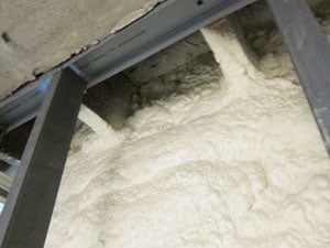
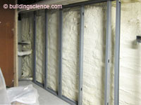
With the basement being used for mechanical equipment, laundry facilities, and storage space, insulation of the basement was included in the project. The approach taken was to apply closed-cell spray foam insulation directly over the existing walls and to place an insulated concrete slab over the existing slab.
All windows were replaced with new construction “triple-glazed” windows. By installing the windows in the outer part of the retrofitted walls, they were easily integrated with the drainage plane and air barrier of the walls and installed without damaging the existing interior walls and trim.
Given the overall approach, the air barrier system consists of discrete parts that needed to be connected, often through layers of materials and transitioning between interior and exterior. In particular, the geometric complexity of the roof and inaccessibility of certain areas made it difficult to design and achieve a fully continuous air barrier system.
Since the project would result in a much tighter building, HRV units were added to each apartment for ventilation.
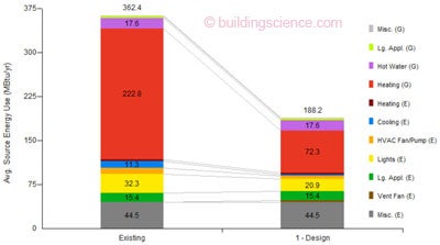
Parametric Study of Source Energy Use
(Image from BSC generated by NREL’s BEOpt 1.1 for retrofits)
Enclosure Design
Roof Assembly: R-60 (nominal) vented attic: existing slate shingles, underlayment, and board sheathing; in knee wall and at sloped ceilings, 1” layer of polyisocyanurate rigid insulation between rafters, held away at least 1” from board sheathing, covered with closed-cell spray foam; attic above flat ceiling has deep layer of cellulose.
Roof Assembly
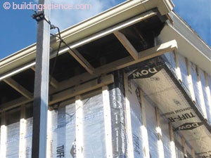
Wall Assembly: R-40 (nominal): Fiber cement cladding installed over 1x4 vertical furring strips; two 2” layers of foil-faced polyisocyanurate insulating sheathing; housewrap applied over existing board sheathing; existing wall cavities filled with blown-in cellulose where needed.
Wall Assembly
Window Specifications: New construction windows–525 series fiberglass Serious Windows: U=0.22, SHGC=0.20; installed in alignment with surface of outer layer of insulating sheathing.

Window Specifications
Air Sealing: Air barrier system is as follows: spray foam on basement floor, interior side of foundation walls, and interior side of rim joist; taped outer layer of insulating sheathing on exterior framed walls; spray foam under roof deck at knee wall and sloped ceiling; flat plaster ceiling in third floor unit; transitions between components made using spray foam and sealant.
Air Sealing
Foundation Assembly: Conditioned basement with 2” closed-cell spray foam applied directly to stone foundation walls and finished with a metal stud framed perimeter wall; 2” closed-cell spray foam applied directly over existing concrete slab and covered with new 11/2” concrete slab.*

Foundation Assembly
* BSC does not recommend the use of spray foam as insulation under a basement slab.
Construction
The construction process for the above grade walls of the house was fairly straightforward since the contractor was experienced with the installation of exterior insulating sheathing and the detailing required for the outer layer to be a drainage plane and part of the air barrier. Although the roof and overhangs were not modified in this retrofit, there were places where special handling was required because the existing overhang was barely sufficient to cover the extra thickness of the retrofitted exterior wall.
To condition the basement, the contractor used a “bathtub” of spray foam created within the existing basement by applying the spray foam directly onto the existing walls and slab. The “bathtub” provides the thermal, air, water and vapor control layers for the basement. BSC recommended that XPS be used as the underslab insulation instead of spray foam and that a water management system be incorporated by placing a drainage mat under the insulation. However, given that the contractor had previous success using the “bathtub” approach, could do this method at a lower cost, and noted that there was no history of water in the basement, the contractor chose to use the spray foam “bathtub” approach.
Mechanical Design
Combined Heating and Power: Retained existing FreeWatt hydronic system that includes a CHP power module that provides electricity for two of the units, a natural gas closed combustion boiler that provides heating for all three units; this uses a pre-existing radiator distribution.
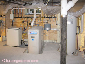
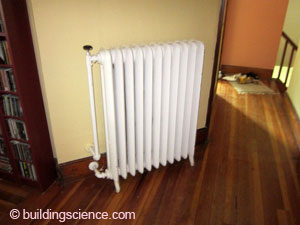
Water heater (left) and pre-existing radiator (right)
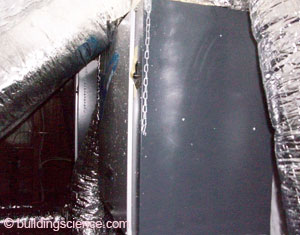
Cooling: New window air conditioners were provided with system of gaskets for sealing and easy installation/removal..

New window air conditioners
Ventilation: For each unit, a Venmar EKO 1.5 HRV (ECM motor and 80% recovery efficiency); outside supply ducted to common space; inside exhaust taken from bathroom; units for upper two floors installed in 3rd floor kneewall space; unit for 1st floor installed in basement.
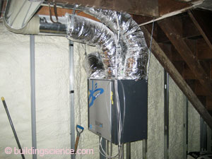
Ventilation system components
DHW: The existing FreeWatt hydronic system includes an indirect hot water tank that provides hot water for all three units.
Lighting: ENERGY STAR® CFL lighting.
Appliances: Existing ENERGY STAR® dishwasher, refrigerator, clothes washer and exhaust hoods for the gas stoves.
Testing and On-Site Technical Support
During the project, BSC visited the site to observe the implementation of the different energy upgrade measures including inspection of installed window details and of insulation before the exterior and interior finishes were applied.
BSC performed blower door testing to determine the overall air tightness of the building before the retrofit started and after the retrofit was substantially complete. The test result was 7729 CFM50 for the entire enclosure (including the basement) before the retrofit. This corresponds to 11 ACH50. The post-retrofit result for the entire enclosure (including the basement and with window air conditioners installed) was 1802 CFM50. This corresponds to 2.5 ACH50.
The National Grid DER goal for this project was 746 CFM50. To assess how much of the leakage was associated with the window air conditioners, another test was run after sealing off the air conditioner units. This improved the results by only 114 CFM. Other places that are likely to be contributing to the air leakage include the transitions between air barrier components at attic, roof, and wall connections, especially where accessibility was an obstacle.

Moving Forward
Agreements between National Grid and the homeowners stipulate that the homeowners will make energy consumption data available for review and analysis for a period including at least two full heating seasons after completion of the project. This, along with feedback from the occupants, will provide valuable information to assist with future DER projects.
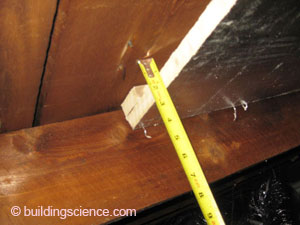
Design Challenge: Don't Touch That Slate Roof! One constraint for this project was that the slate roofing material was not to be removed. Since it could not be removed, this eliminated the option of adding insulation to the outside of the roof deck. It also meant that the water management layer under the roofing could not be inspected and, if necessary, improved. Even a slate roof that is in good condition and has proper water management details is going to allow some water to get to the underlying board sheathing. This is not a problem provided the moisture can be absorbed into the board sheathing and redistributed enough to allow drying. For this project, in order to get an insulation value close to the National Grid DER goal of R-60 while insulating only from the inside, the rafter bays needed to be filled with closed-cell foam insulation in the knee wall and sloped ceiling spaces. However, closed-cell spray foam insulation applied directly to the underside of the board sheathing severely restricts the ability to dry because there is no air gap below the boards and the spray foam is vapor impermeable. For this reason, BSC does not recommend applying spray foam directly under the roof deck of an unvented roof where the water management system of the roof cannot be verified. A remedial measure was devised for the project by placing a 1” rigid polyisocyanurate board in each rafter bay held back from the board sheathing by at least 1”. The air gap created under the sheathing supports redistribution and drying, provides a relatively high R-value, and served as the backer for the application of the closed-cell spray foam in the rafter bays.
|