Liquid Flow Due to Capillary Suction
One moisture transport mechanism that is often overlooked in building construction is capillarity or capillary suction. Capillary suction acts primarily to move moisture into porous materials. For example, a paper towel, with one end in contact with liquid water, draws water into itself against the force of gravity as a result of capillary suction.
Capillarity is a function of - among other things - pore size and available moisture. If pore size in a material is large, such as clear gravel and coarse sand, then capillarity will not exist. If pore size in a material is small, such as in concrete, silty clay, and paper, then capillarity is possible. Photograph 1 shows ground water drawn into porous brick in contact with the ground. Mother Nature, in her effort to educate builders and architects, thoughtfully provides chlorophyll as a tracer pigment in this case to illustrate capillary rise.
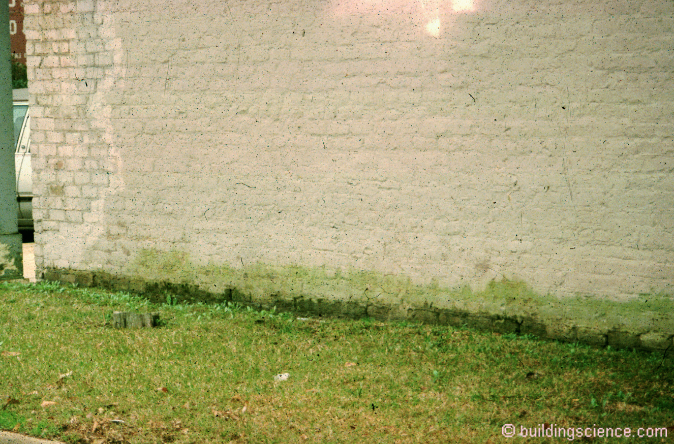
Photograph 1: Capillary Rise in Pores - Ground water is drawn into porous brick in contact with the ground. Mother Nature, in her effort to educate builders and architects, thoughtfully provides chlorophyll as a tracer pigment in this case to illustrate capillary rise.
Capillarity will not exist in materials that do not have pores such as glass, steel, and most plastics. However, if two materials that do not have any capillary pores are placed closely enough together, such as two panes of glass, the space between them can itself become a capillary pore. Another example of this phenomenon is the migration of solder by capillarity into the tight space between a plumbing pipe inserted in a plumbing fixture. Photograph 2 shows water rising between two panes of glass separated by a paper clip on one end, and clamped together on the other end. Note the curved shape of the wetting pattern of water as the space between the two panes of glass is reduced1.
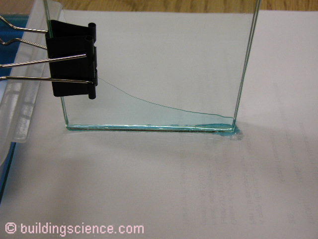
Photograph 2: Capillary Rise in Cracks - Water rising between two panes of glass separated by a paper clip on one end, and clamped together on the other end. Note the curved shape of the wetting pattern of water as the space between the two panes of glass is reduced.
Capillary suction pressures are a result of surface tension - specifically the attraction of water to surfaces. Figure 1 illustrates the attraction or non-attraction of water to surfaces. Where a droplet of water “beads up” on a surface the water is said to be more attracted to itself than the surface. Where a droplet of water “spreads out” on a surface the water is said to be more attracted to the surface than itself. This illustrates the difference between “wettable” and “non-wettable” surfaces….”hygroscopic” and “hydrophobic” surfaces.
A physicist would say that the surface energy of the water is greater than the surface energy of the surface for a hydrophobic surface and that the surface energy of the surface is greater than the surface energy of the water for a hygroscopic surface. The degree of attraction or non-attraction is determined by the contact angle (also shown in Figure 1).
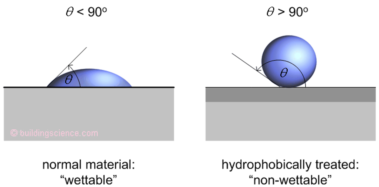
Figure 1: Water on Surfaces - Where a droplet of water “beads up” on a surface the water is said to be more attracted to itself than the surface. Where a droplet of water “spreads out” on a surface the water is said to be more attracted to the surface than itself. This illustrates the difference between “wettable” and “non-wettable” surfaces….”hygroscopic” and “hydrophobic” surfaces.
Figure 2 illustrates the effect of surface tension forces “pulling” water upwards in a glass tube while being resisted by the gravity force “pulling” water downwards. The smaller the “gap” or “pore” the greater the surface tension forces acting upwards.
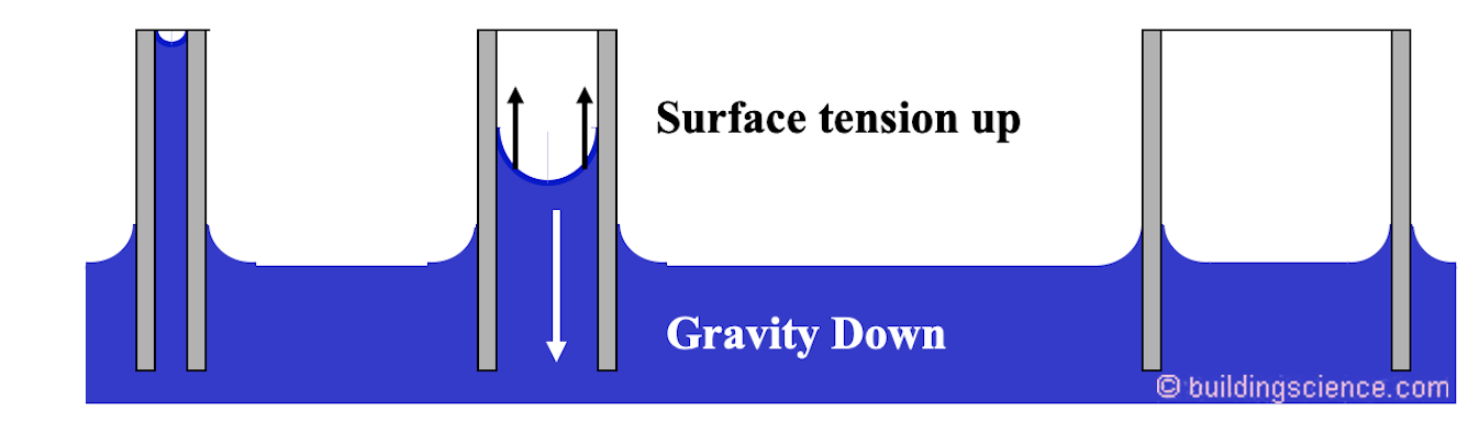
Figure 2: Surface Tension vs Gravity - Surface tension forces “pull” water upwards in a glass tube while being resisted by the gravity force “pulling” water downwards. The smaller the “gap” or “pore” the greater the surface tension force acting upwards.
The height that capillary suction will draw water in a cylindrical glass tube is shown in Figure 3. The derivation of the equation is based on the Kelvin equation, Laplace-Young equation and the Washburn equation. The derivation is beautifully presented by Burnett and Straube, 2005 and Hutcheon and Handgord, 1983.
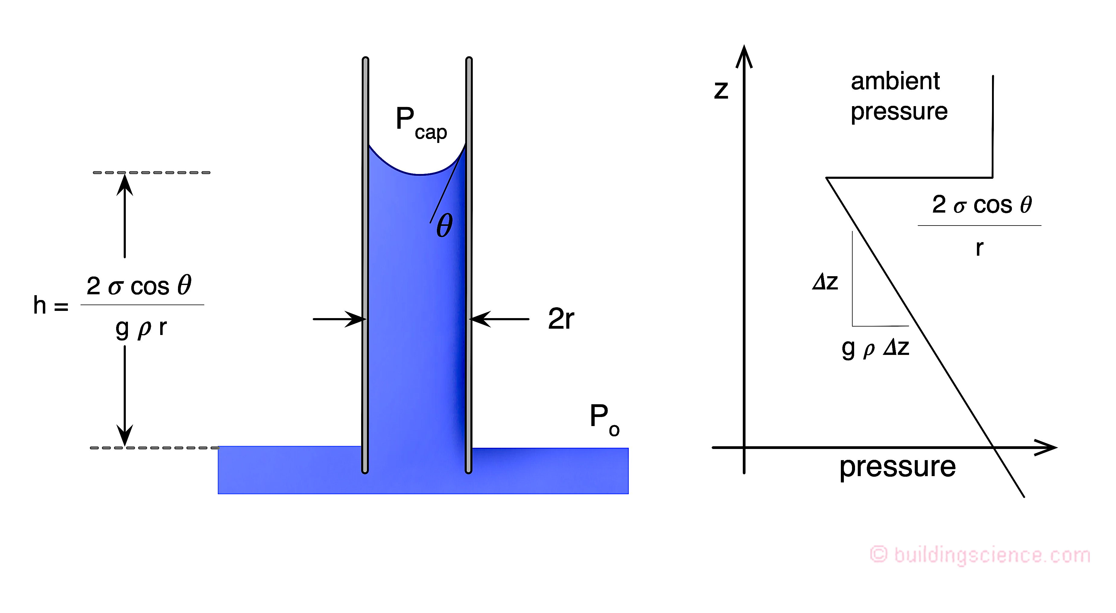
Figure 3: Capillary Suction Height - The derivation of the equation is based on the Kelvin equation, Laplace-Young equation and the Washburn equation. The derivation is from Burnett and Straube, 2005 and Hutcheon and Handgord, 1983.
Figure 4 plots the relationship of pore size/crack width versus height. Note the shape of the curve. Now look back at Photograph 2. Don’t you just love this? Eh?
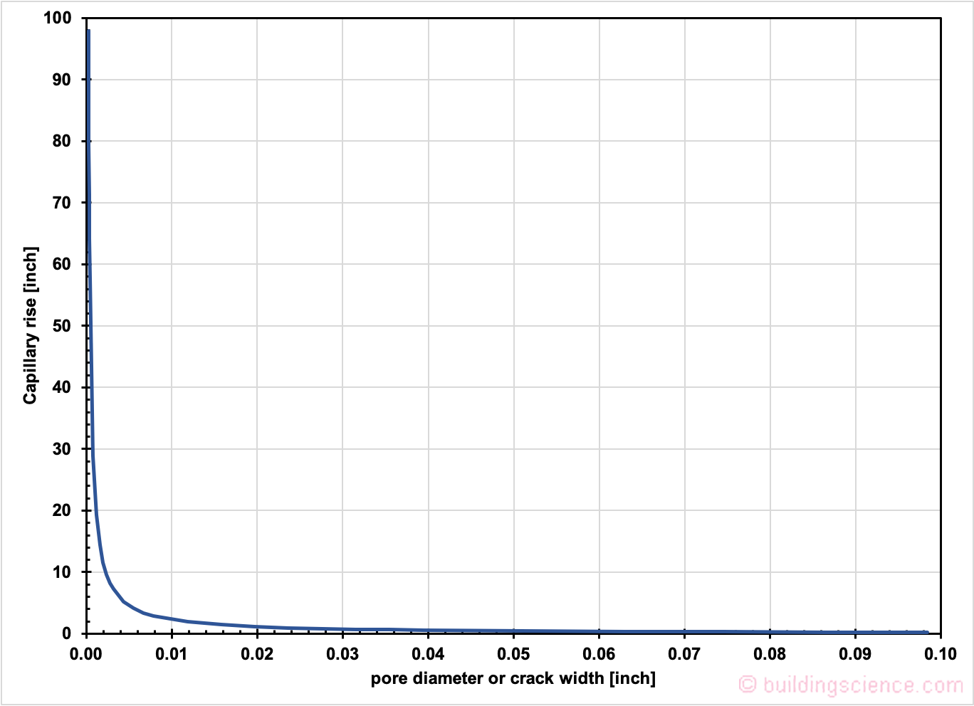
Figure 4: Pore Size/Crack Width Versus Height – Courtesy of John Straube, “The Physics of Building Science”, Westford Symposium, 2001.
Capillarity can be significant in the portions of building enclosures where they are below grade or where they come in contact with the ground. An example of this is a concrete footing cast on damp soil. Concrete is porous and susceptible to capillarity. Capillary water is drawn up into the footing and then into the perimeter concrete foundation wall. Once in the foundation wall the capillary water can evaporate into the interior of the basement at the bottom of the foundation wall. This often manifests itself as a ring of dampness visible around the perimeter of the basement foundation at the base of the wall (Figure 5). This mechanism is also referred to as rising damp. Similar issues can exist with slab foundations at grade (Figure 6).
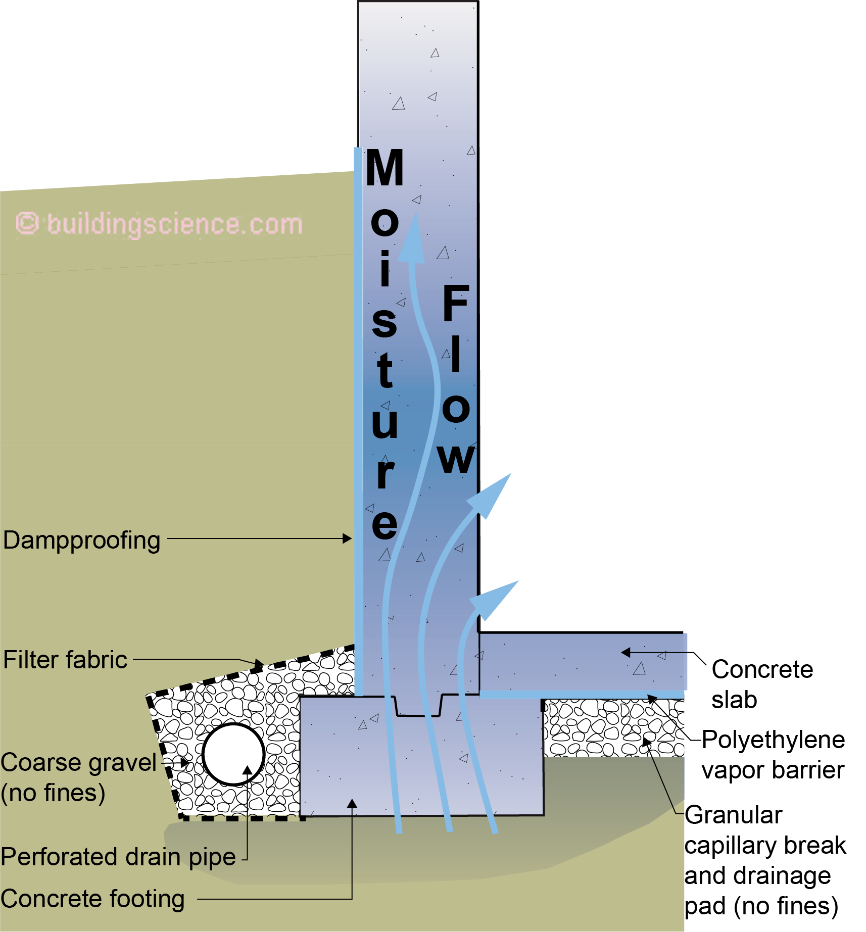
Figure 5: Capillarity – Footings typically do not have capillary breaks.
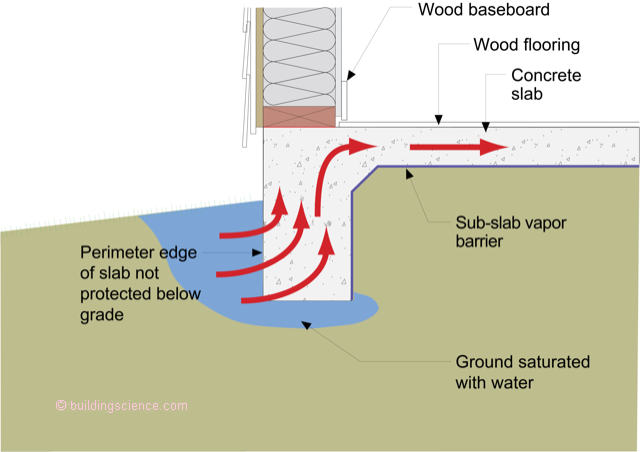
Figure 6: Capillarity - Monolithic slabs are typically unprotected at slab perimeters.
Capillary suction can also be a factor in building enclosures above grade where a film of water is deposited on the exterior of the building enclosure as a result of rainfall or dew formation. This water film may be drawn into the building enclosure under the action of capillary suction. This is illustrated by the water trapped between the laps in horizontal wood siding. The water is held between the laps in spite of the influence of gravity (Figure 7 and Photograph 3). As such, joints between materials exposed to water, above and below grade, should be designed with capillarity in mind.
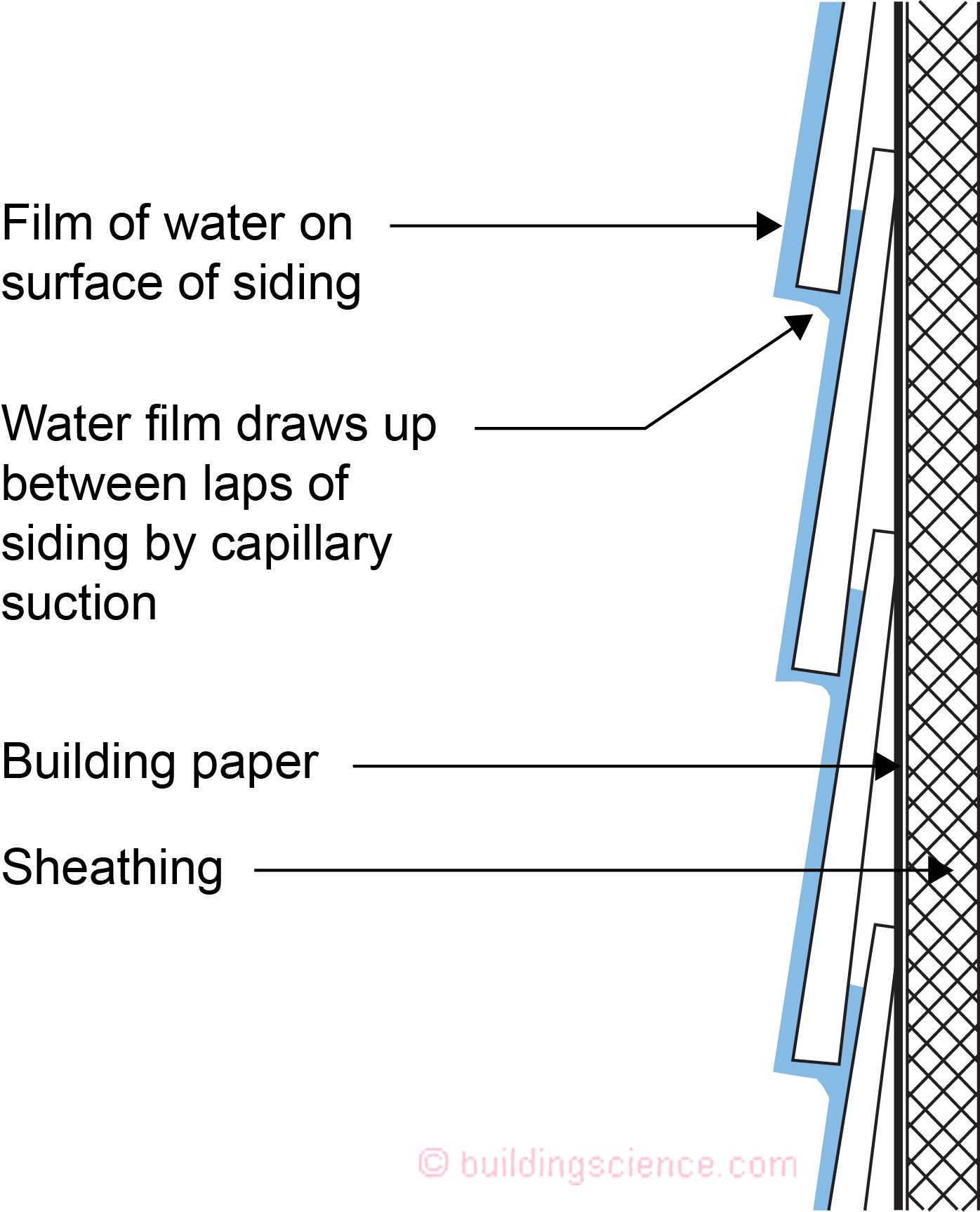
Figure 7: Capillarity Above Grade - Water trapped between the laps in horizontal wood siding.
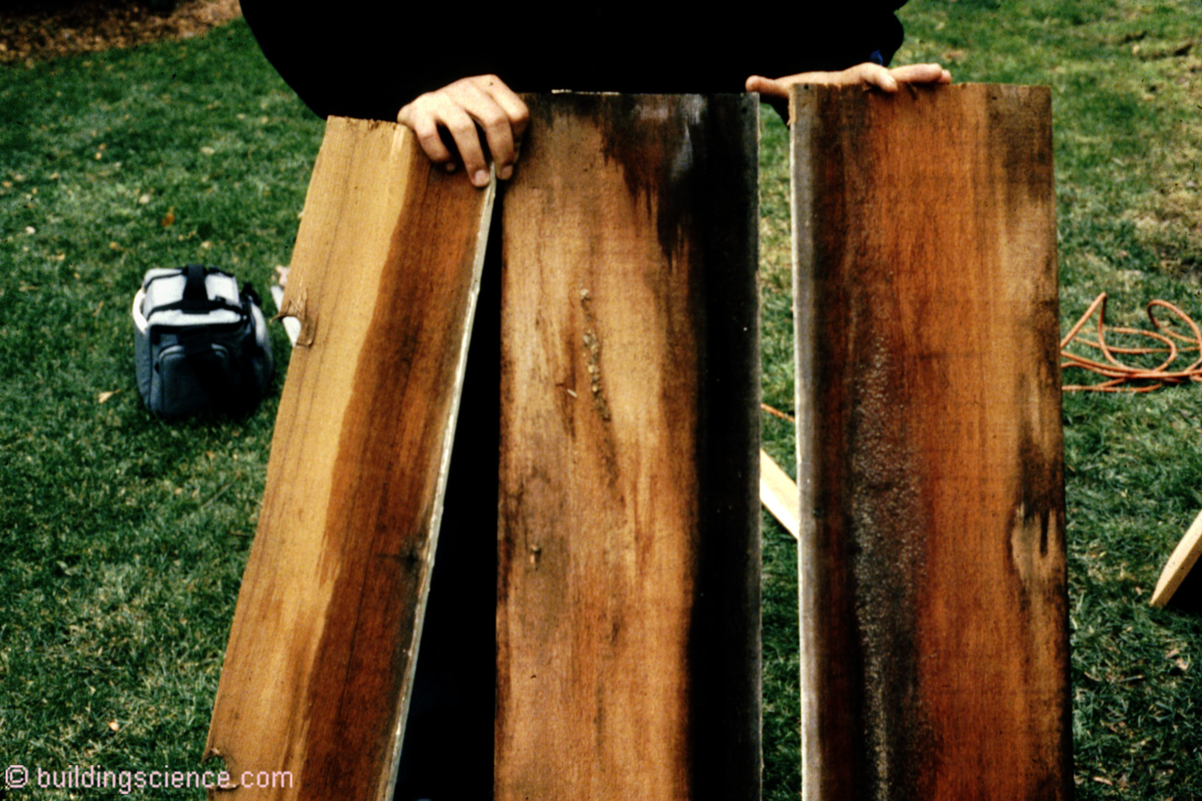
Photograph 3: Capillary Rise Between Lapped Wood Siding – Damage to wood siding from water trapped between the horizontal laps.
A designer or builder can control capillarity by controlling the availability of capillary moisture and the pore size of the building material or building assembly selected. Materials can be selected that do not support capillarity due to their large pore size such as gravel, or materials may be selected that do not have any pores, such as glass. Alternatively, capillary pores in susceptible materials can be filled to break the capillary draw such as is done where concrete basement foundation walls are dampproofed. Capillarity can be controlled by sealing connections between materials (caulking joints) or by making the connections wide enough not to support capillarity. Furthermore, a receptor for capillary moisture can be provided such as an air space or a porous material. Capillarity can, therefore, be controlled as follows:
- Controlling the availability of capillary moisture
- Sealing capillary pores
- Making capillary pores larger
- Providing a receptor for capillary moisture
Capillary Suction with Groundwater as the Moisture Source
Capillary suction in concrete foundation walls is traditionally controlled by dampproofing the exterior surface of the wall where it is in contact with the surrounding damp soil (Figure 8). This dampproofing film is typically not meant to span cracks or large openings, and as such it is not a waterproofing membrane. Whereas waterproofing membranes provide an excellent capillary break, dampproofing films are usually poor waterproofing membranes.
Capillary suction under concrete floor slabs is traditionally controlled by placing the floor slab over large-pore gravel (3/4 inch crushed stone with fines removed). Since the pore size in the granular pad is too large to support capillary suction, the granular pad acts as a capillary break (Figure 8). A sheet polyethylene layer installed directly under the concrete floor slab in direct contact with the concrete floor slab can also act as a capillary break.
Capillary suction in masonry block foundation walls is traditionally controlled by coating the exterior surface of the masonry blocks with thin layer of mortar (parge coat or rendering) and then applying a dampproof coating over it. Applying a dampproof coating directly on the masonry blocks has not always proven successful as the pore size of the mortar joints and the pore opening in the masonry block surfaces themselves can be too large for a fluid-applied dampproof coating to span.
Capillary breaks can also be located over the top of concrete footings prior to the construction of perimeter foundation walls (Figure 8, Photograph 4 and Photograph 5) as well as between the top of the foundation walls and framing to prevent construction moisture in the foundation wall from migrating into the floor framing.
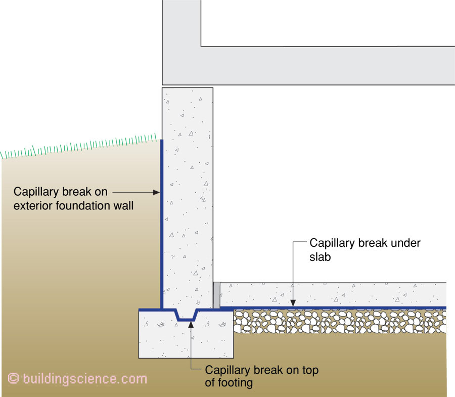
Figure 8: Capillary Breaks Below Grade - Capillary suction in concrete foundation walls is traditionally controlled by dampproofing the exterior surface of the wall where it is in contact with the surrounding damp soil.
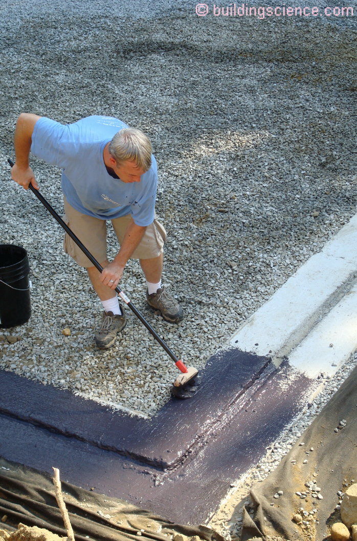
Photograph 4: Footing Capillary Break – Fluid applied capillary break located over the top of concrete footings prior to the construction of perimeter foundation walls
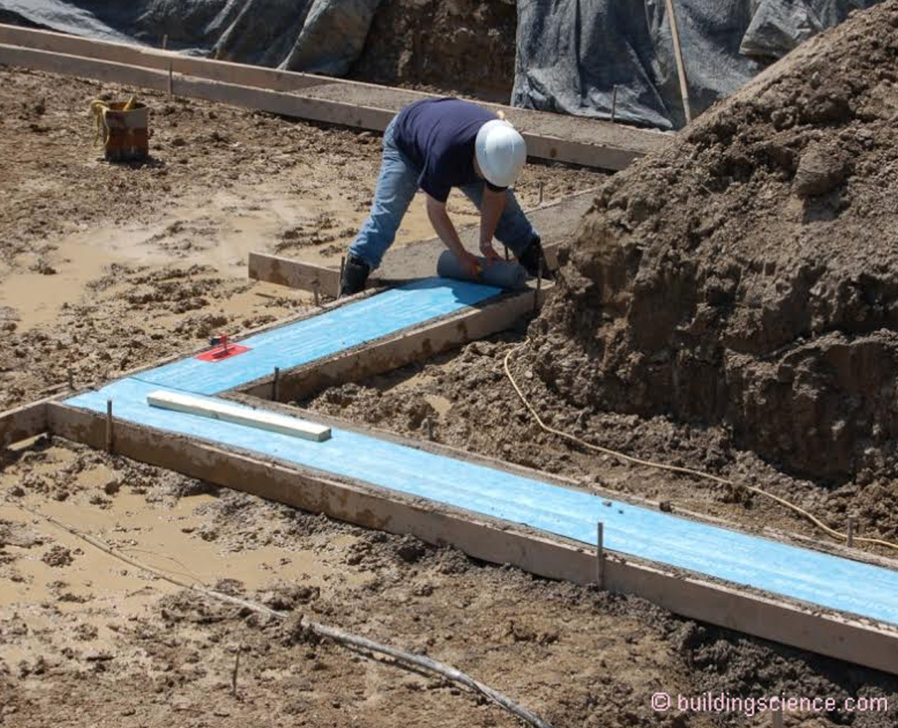
Photograph 5: Footing Capillary Break – Membrane applied capillary break located over the top of concrete footings prior to the construction of perimeter foundation walls
Capillary control also applies to slab-on-grade construction and crawlspaces. Monolithic slabs need polyethylene ground covers that extend under the perimeter grade beam and upwards to grade (Figure 9). Additionally, the exposed portion of slabs should be painted with latex paint to reduce water absorption and a capillary break should be installed under perimeter wall framing.
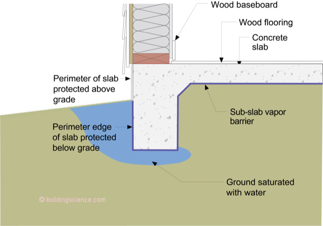
Figure 9: Monolithic Slabs - Polyethylene ground covers should extend under the perimeter grade beam and upwards to grade. Additionally, the exposed portion of slabs should be painted with latex paint to reduce water absorption and a capillary break should be installed under perimeter wall framing.
Capillary Suction with Rainwater as the Moisture Source
Capillary suction in porous cladding materials can be controlled by sealing or filling the pores. One of the most common examples of this is the application of a paint film on wood-based siding to reduce the absorption of deposited rainwater. The paint film seals the capillary pores on the surface of the wood. All six surfaces of the siding (the front, the back, the edges and the end cuts) should be sealed. Additionally, the siding should be installed over an air space behind the siding to act as a receptor for capillary moisture (Figure 10).
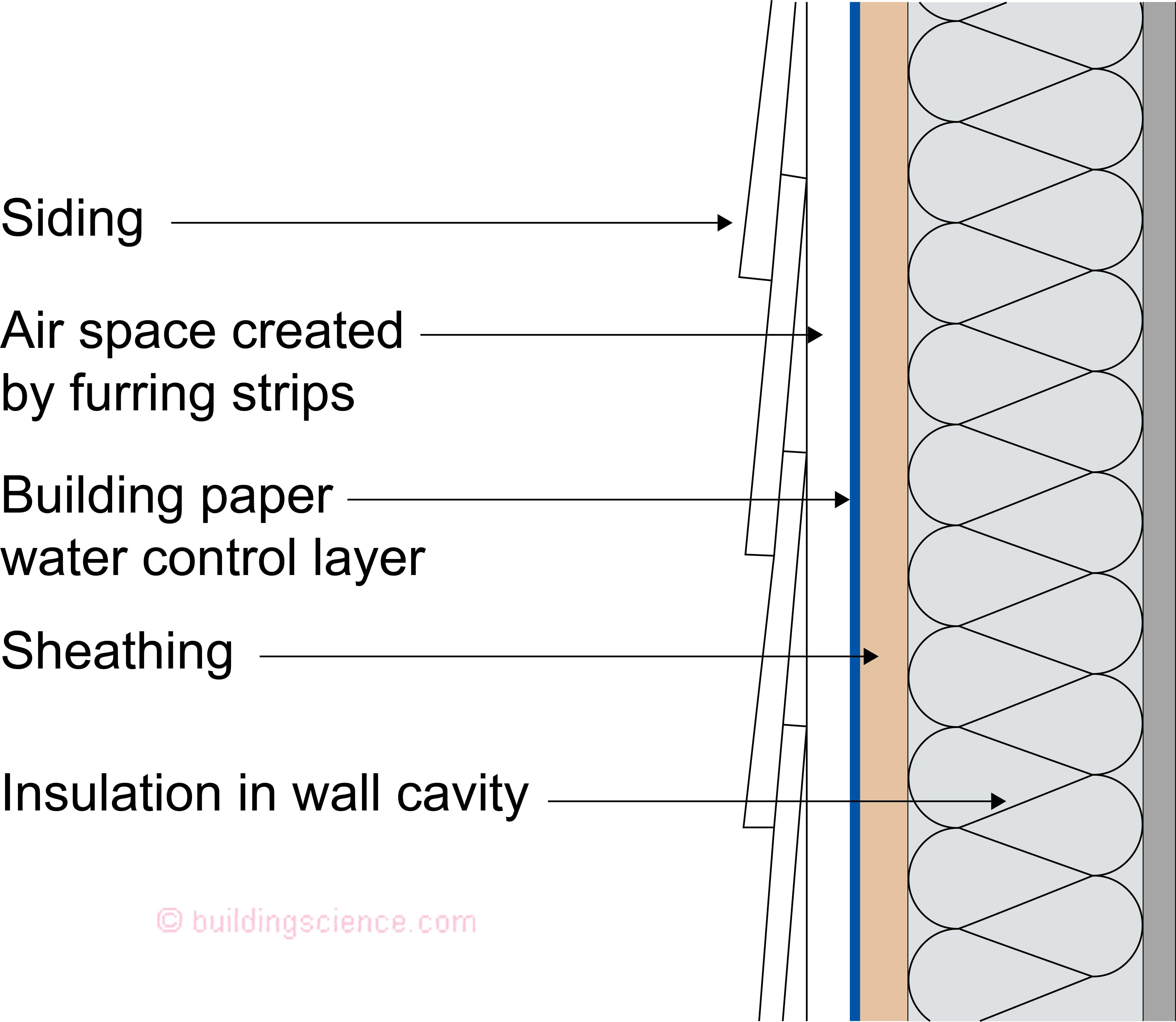

Figure 10: Capillary Control Above Grade - The paint film seals the capillary pores on the surface of the wood. Additionally, the siding should be installed over an air space behind the siding to act as a receptor for capillary moisture.
Siding can be gapped to provide a capillary break. Siding wedges have been used in the past to address peeling paint problems resulting from capillary rise between overlapping siding (Photograph 6). See also sidebar.
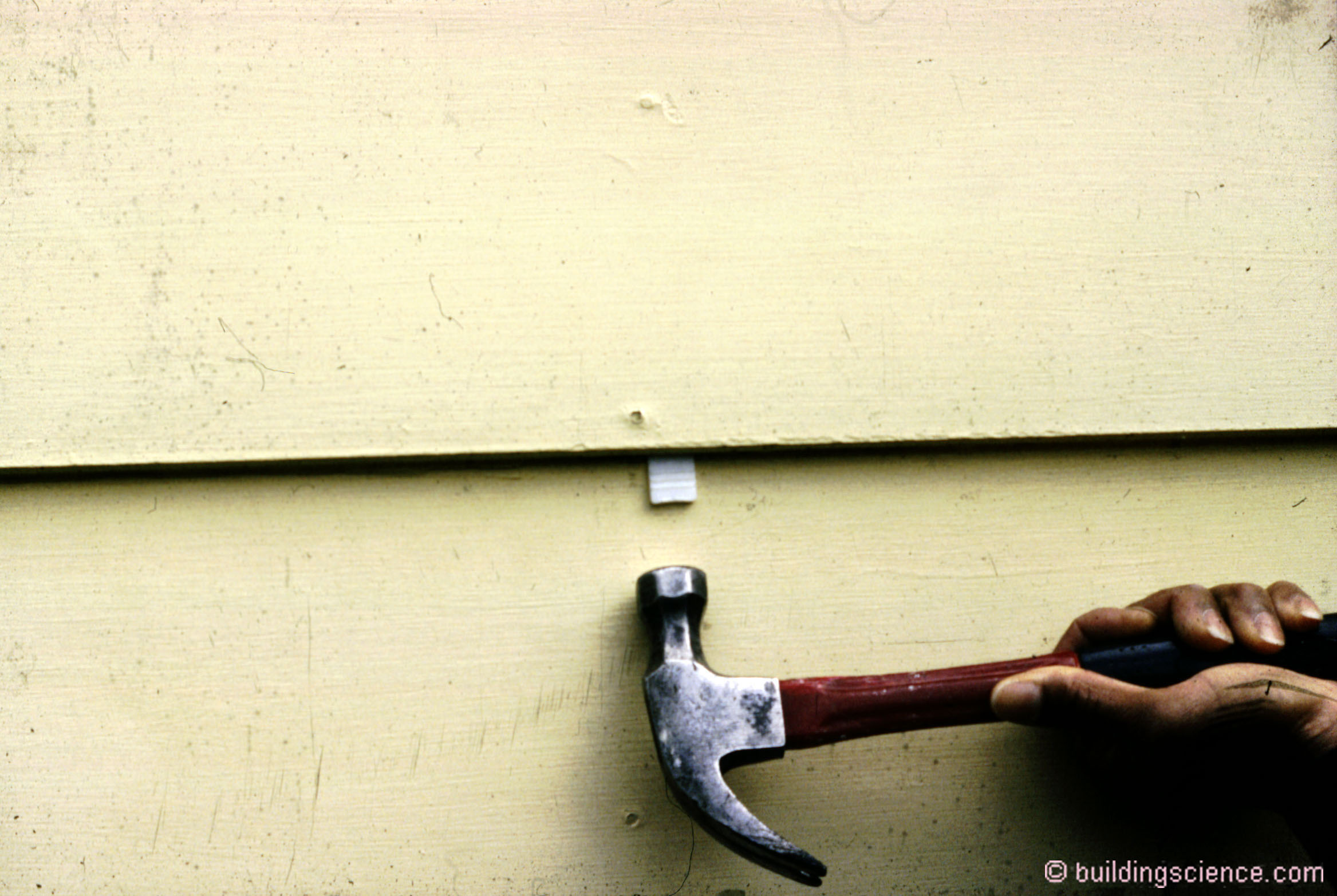
Photograph 6: Retrofit “Wedgie” - Siding can be gapped to provide a capillary break. Siding wedges have been used in the past to address peeling paint problems resulting from capillary rise between overlapping siding.
An additional example of an air space serving as a capillary break as well as serving as a receptor for capillary moisture is where a brick veneer is constructed over an air space (Figure 11). Significant amounts of deposited moisture can be absorbed by the bricks (brick is a “reservoir cladding”). When solar radiation warms the brick veneer, the moisture in the bricks is driven inward out of the bricks into the air space.
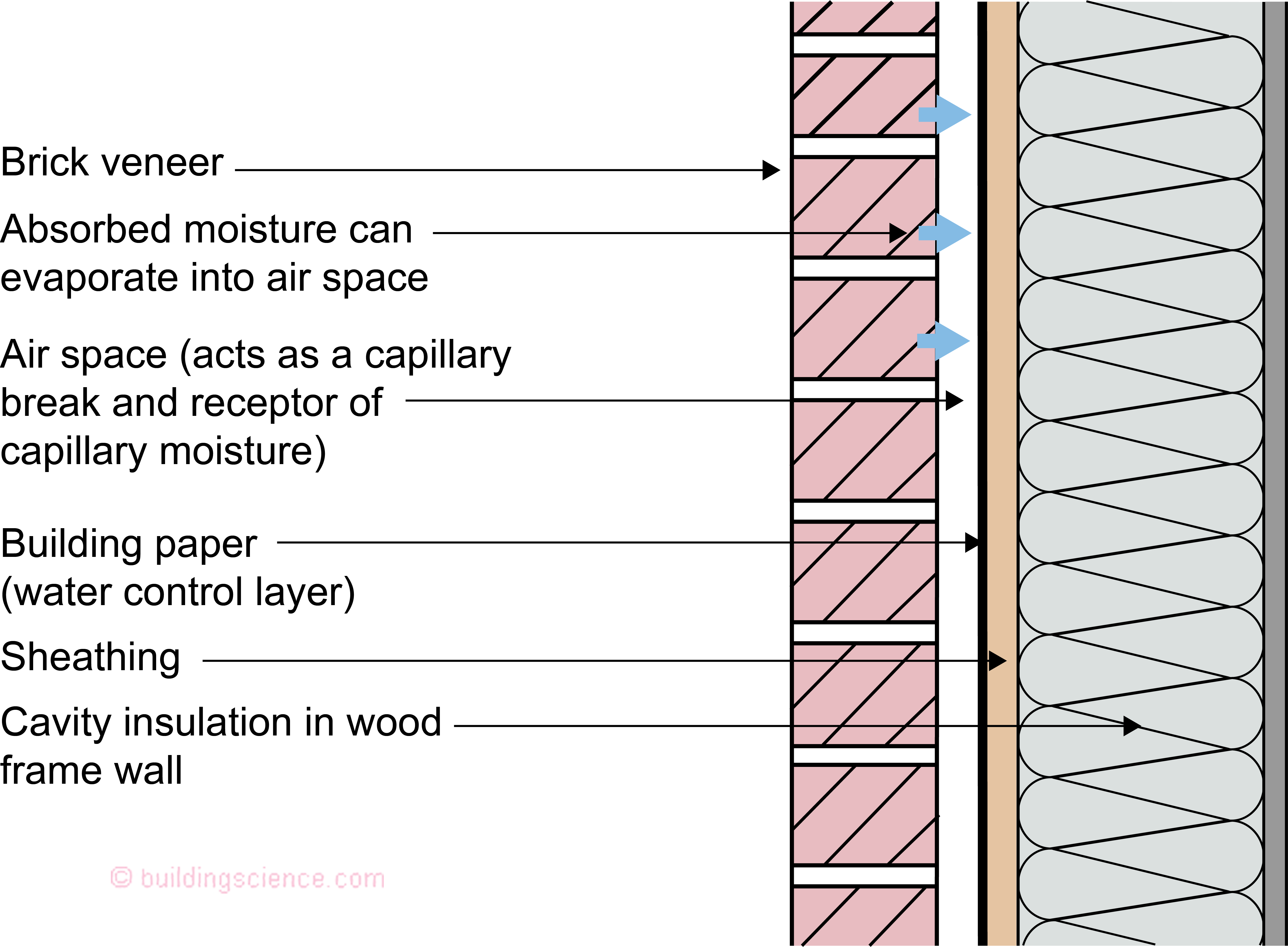
Figure 11: Brick Veneer - Air space serving as a capillary break as well as serving as a receptor for capillary moisture.
Wood or wood trim pieces should be sealed or coated or painted on all six surfaces to control capillary absorption of water (Figure 12). Additionally, these trim pieces should be installed over an air space (Figure 13).
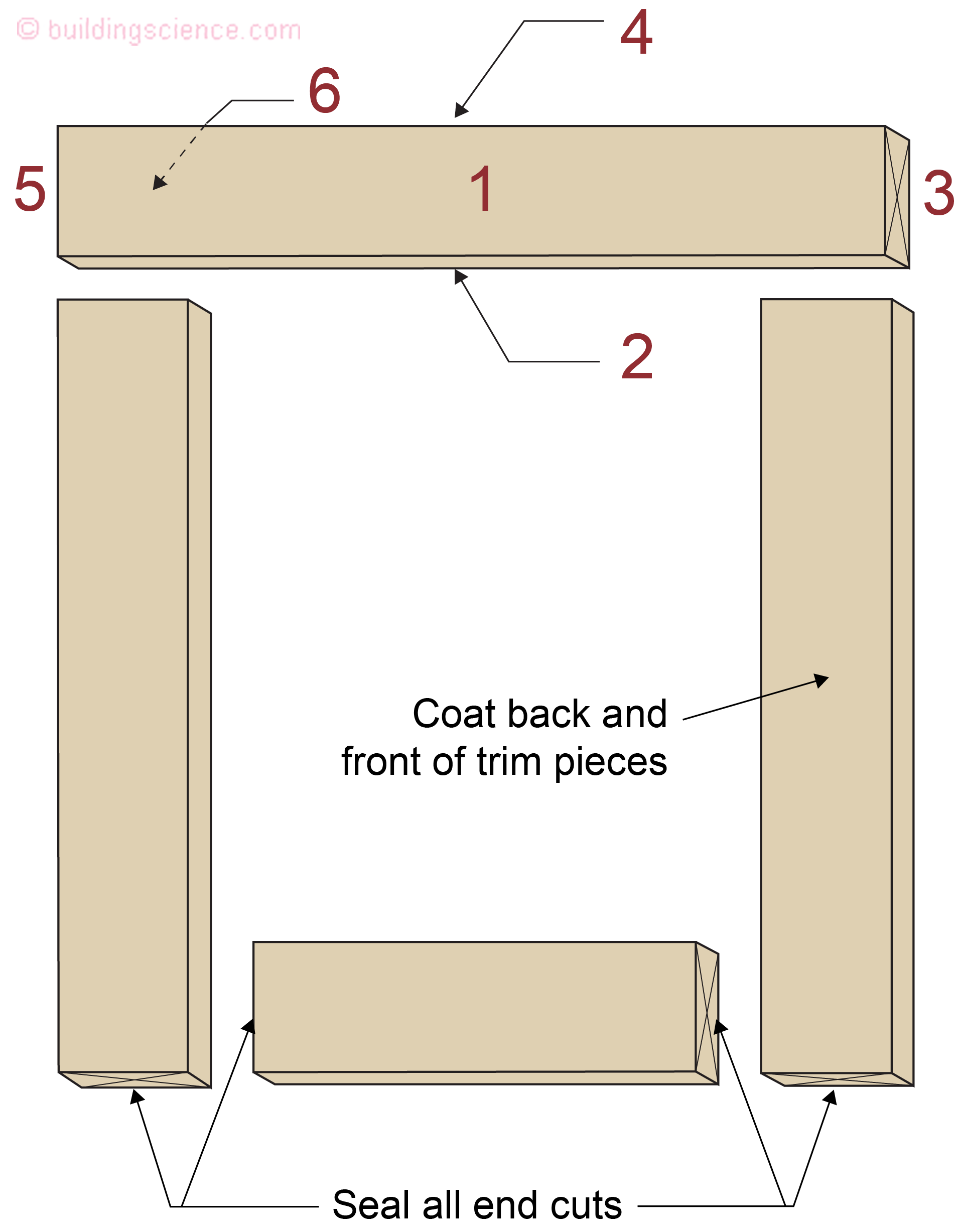
Figure 12: Wood Trim - All six surfaces of the trim (the front, the back, the edges and the end cuts) should be sealed.
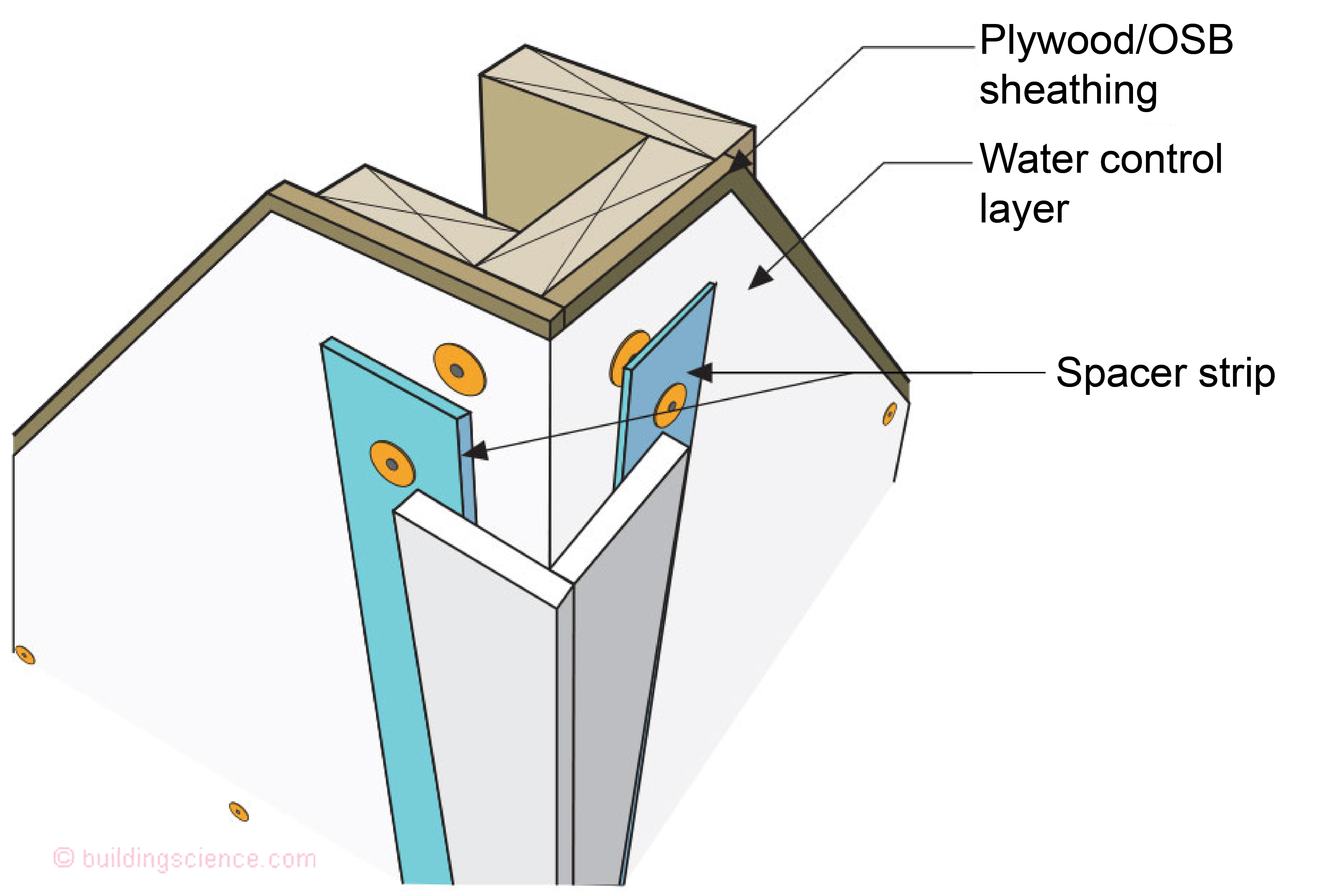
Figure 13: Wood Trim Over Air Space – Air space serves as a receptor for capillary moisture.
Where wood shingles and shakes are installed over furring strips, or skip-sheathing on roof assemblies (Figure 14), the same phenomenon occurs. The wood shakes and shingles absorb deposited rainwater due to capillary suction. The wood shakes and shingles dry to both directions. The function of the building paper/roofing paper is to facilitate drainage and air pressure moderation across the roof assembly. The shakes/shingles are leaky, whereas the building/roofing paper is tight. Where sheet goods are used for roof sheathing (such as plywood or oriented strand board/OSB) with wood shakes and shingles an air gap must be added between the shakes and shingles to act as a receptor for the capillary moisture. The air gap is typically provided using a breathable drainage mesh (Figure 15).
Life sometimes sucks….Sometimes you need to give it some space….
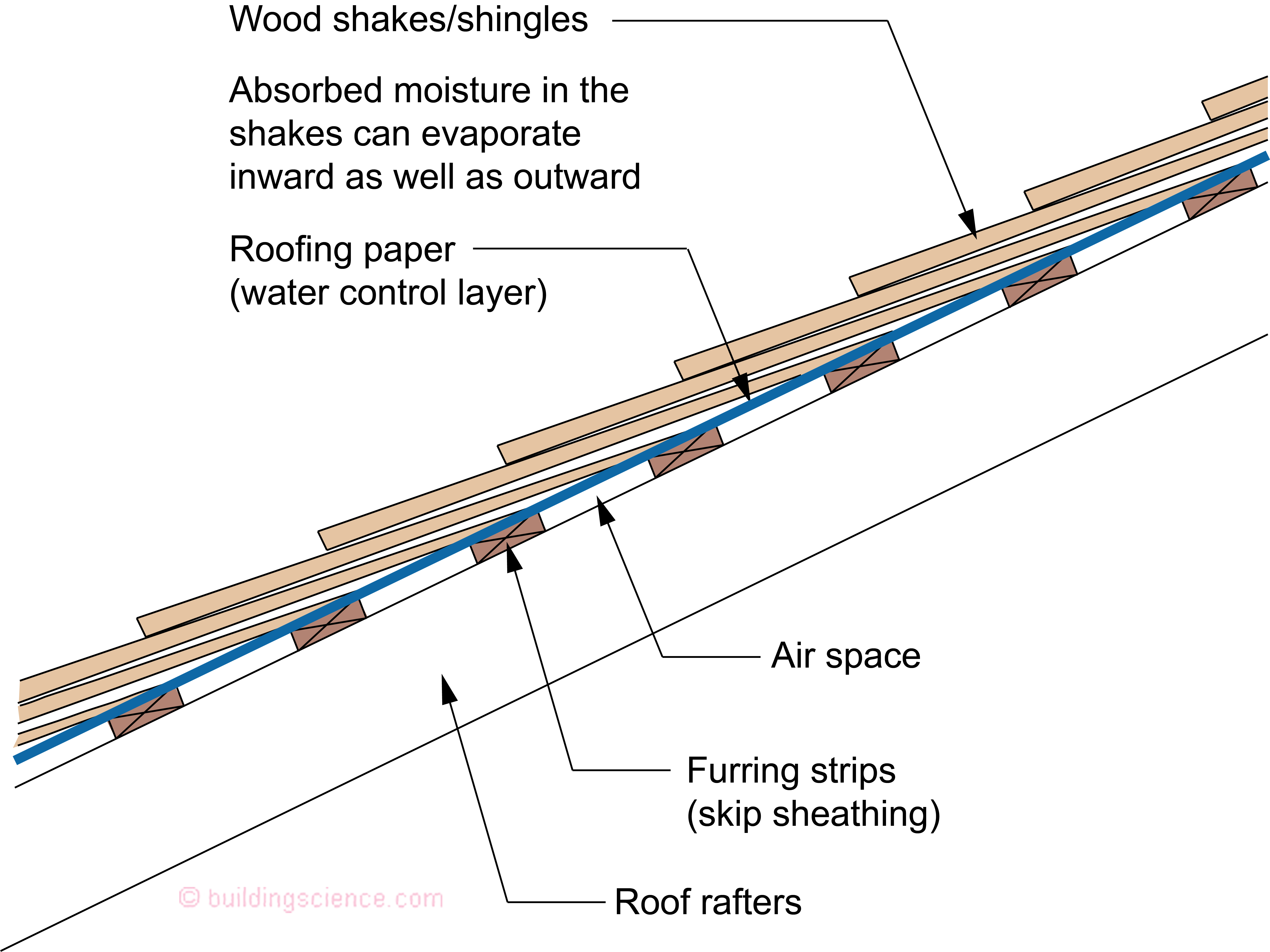
Figure 14: Wood Shingles and Shakes - The wood shakes and shingles absorb deposited rainwater due to capillary suction. The wood shakes and shingles dry to both directions.
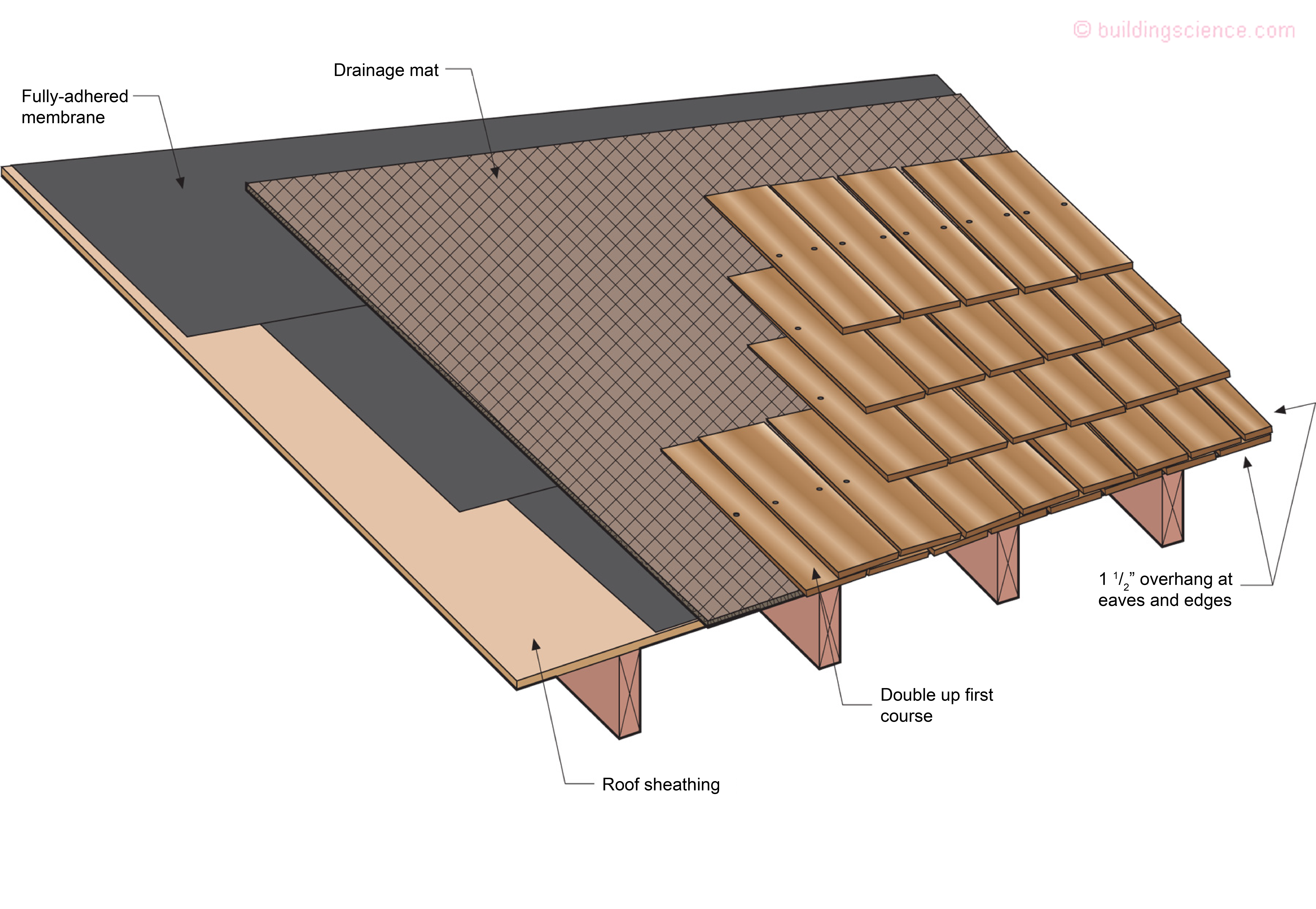
Figure 15: Sheet Goods and Wood Shingles and Shakes - Where sheet goods are used for roof sheathing such as plywood or oriented strand board (OSB) in conjunction with wood shakes and shingles an air gap must be added between the shakes and shingles to act as a receptor for the capillary moisture. The air gap is typically provided using a breathable drainage mesh.
Sidebar
In the mid 1980’s I was looking at peeling paint problems on wood siding. I linked the problems to capillary rise between the overlaps in the siding and a reduction in drying potential due to an increase in thermal insulation in wall cavities. I wrote it up for the CIB-W40 Meeting, Victoria, BC., September, 1989 based on a paper presented at the Energy Efficient Building Association (EEBA) 5th Annual Conference and Exposition, November, 1987. Republished in the Journal of Thermal Insulation, January 1990.
Check out Sidebar Figure 1, Sidebar Figure 2, Sidebar Figure 3 and Sidebar Figure 4…..all from that paper. Not very complicated to avoid the issues, we just don’t do it. Sucks, doesn’t it? The capillarity….
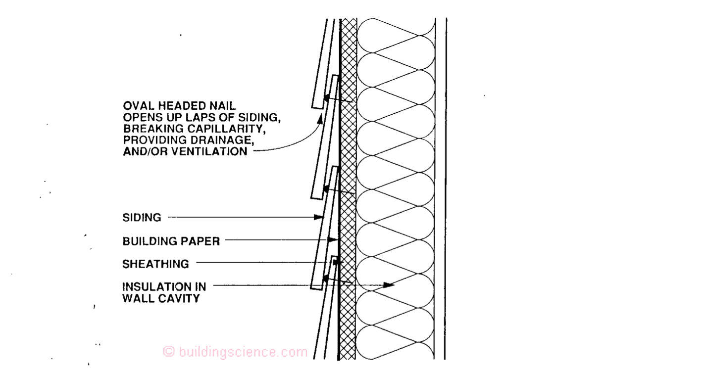
Sidebar 1: Oval Headed Nail – Blind nailed oval headed nail creating a capillary break.
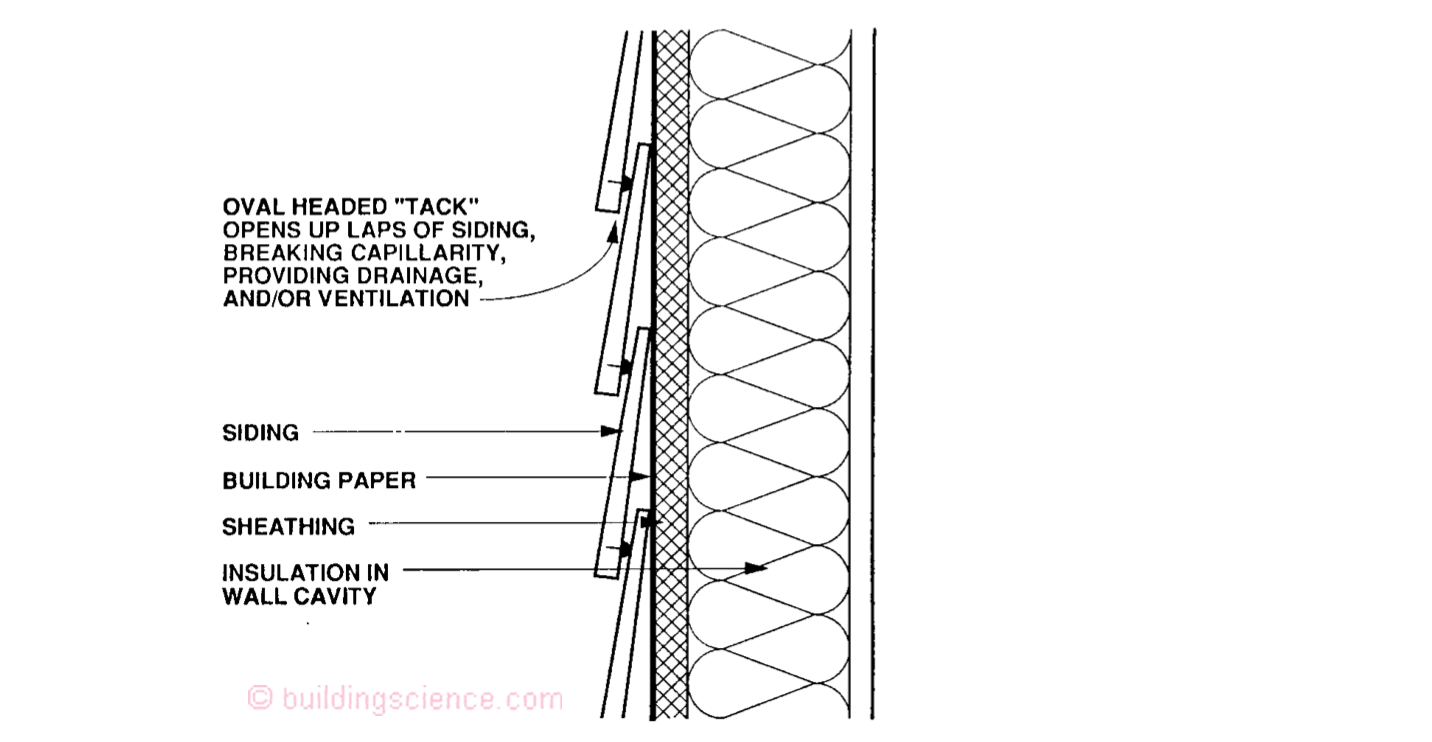
Sidebar 2: Oval Headed Tack – Spacer on the back of siding creating a capillary break.

Sidebar 3: “Wedge” – Plastic wedge between the laps of siding creating a capillary break.
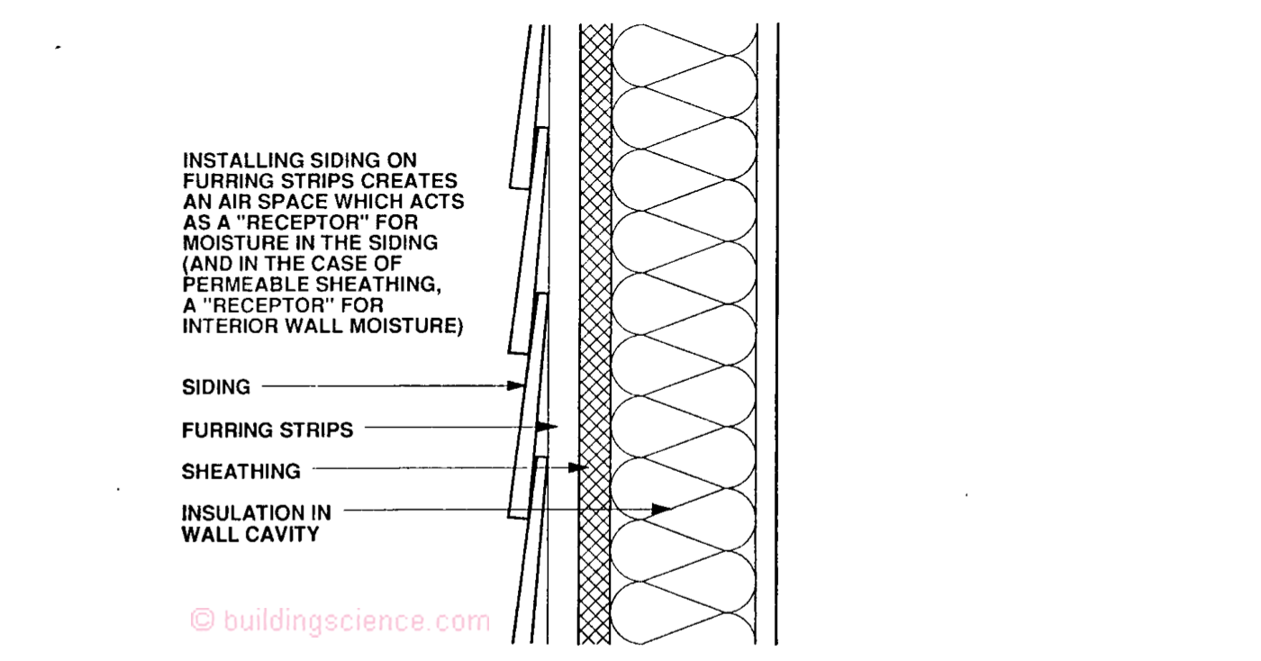
Sidebar 4: Furring Strips – Air space created by furring strips provides a “receptor” for capillary moisture.
Footnotes
1 Amazing what a smart person can do with a paper clip, two panes of glass, water, a binder clip and no budget. Photograph courtesy of John Straube.
References
Hutcheon, N.B., and G.O.P. Handegord, Building Science for a Cold Climate, Wiley, Toronto, ON., 1983.
Straube, J.F., and E.F.P. Burnett, Building Science for Building Enclosures, Building Science Press, Westford, MA., 2005.