Things have evolved considerably since the Eisenhower and Diefenbaker years. Hutcheon2 taught us about air flow that decade but it took more than a half century to get it right. We needed air control. We needed an air control layer – an air barrier. We started off with locating it on the inside, moved it to the middle, and finally ended up with it on the outside3. We started by combining it with a vapor barrier on the inside then we finished by combining it with a weather resistive barrier (WRB) and continuous insulation on the outside (Figure 1, Figure 2, Figure 3, Figure 4, Figure 5, and Figure 6).
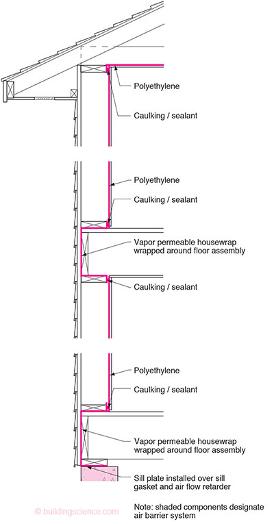
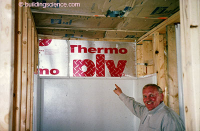
Figure 1: Polyethylene Air-Vapor Barrier—The period of “black death” where acoustical sealant that was black in color was used to seal overlapping sheets of 6 mil polyethylene to create a continuous air barrier. Note that where the membrane sheet wrapped the exterior rim joist it needed to be vapor open. Vapor open “housewraps” or plastic building papers were used in these locations.
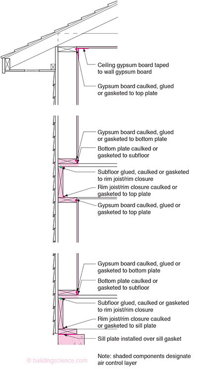
Figure 2: The “Airtight Drywall Approach”—The interior gypsum board lining became the air barrier. The approach was more robust than polyethylene air-vapor barriers and since gypsum board was not a vapor barrier the approach could be used in any climate. However to get to similar extraordinary levels of airtightness painstaking effort was still required.

Figure 3: The Interstitial Air Barrier-Airtightness can also be provided within building framing elements. This is most commonly achieved using spray polyurethane foam (SPF).
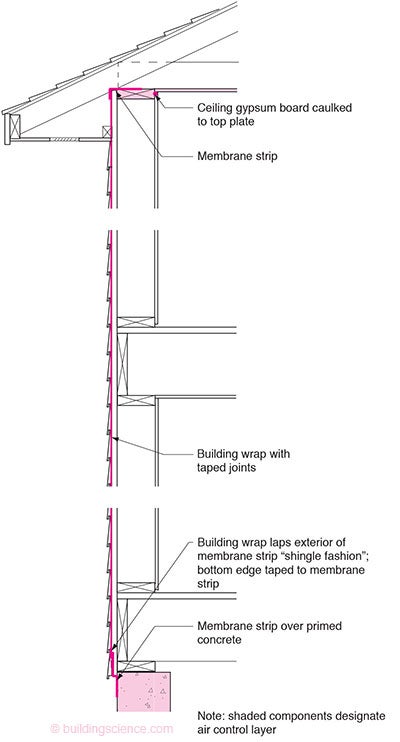
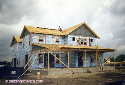
Figure 4: Air Infiltration Barrier—Plastic housewraps were developed and had two functions – rainwater control and air control.
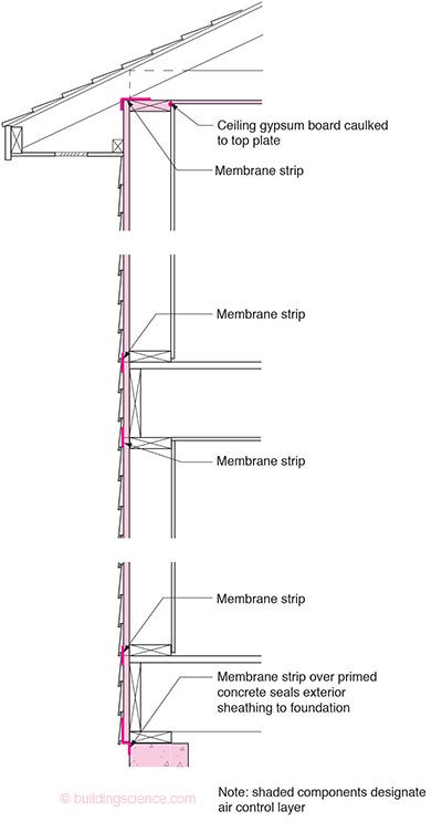
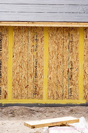
Figure 5: Exterior Sheathing Air Barrier—Turning the sheathing itself into both the water control layer and air control layer.
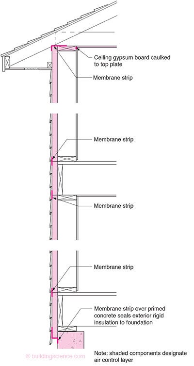
Figure 6: Insulating Sheathing Air Barrier—Adding the function of thermal control to the sheathing in addition to water control and air control.
Throughout the postwar years practitioners were taught, incorrectly, that vapor barriers were necessary in cold climates to protect wall assemblies from moisture damage and that it was necessary to install these vapor barriers on the interior of cavity insulation. The industry saw the introduction of kraft facings and foil facings on batt insulations as a result. These vapor barriers were by their very nature discontinuous and they proved ineffective in protecting wall assemblies from vapor. Vapor is principally transported by air flow not by vapor diffusion. We needed air barriers not vapor barriers to control vapor flow. It took decades for that distinction to be appreciated.4
The first attempt at addressing the issue was to take a vapor barrier material and turn it into an air barrier. The result was coined an “air-vapor barrier”. Sheet polyethylene was already being installed on the interior of insulated wall assemblies as a vapor barrier (Photograph 1). It was given a second function – that of air control. Easy to do conceptually - very difficult to do in practice. With painstaking effort and attention to detail extraordinary levels of airtightness were achieved using this approach – less than 1 ach@50Pa. Canada’s R-2000 program was based on this approach. The sealant used was “acoustical sealant” as it would remain flexible over the service life of the building. It soon got the moniker of “black death” as it got on to everything including the installer. It became clear that the approach was not a “production friendly” method of achieving airtightness and it was not “robust” in terms of surviving the construction process and in providing performance over the service life of the building. It was also climate sensitive. It made no sense for assemblies that saw air conditioning – it was a vapor barrier on the wrong side of and air-conditioned wall (Figure 1).
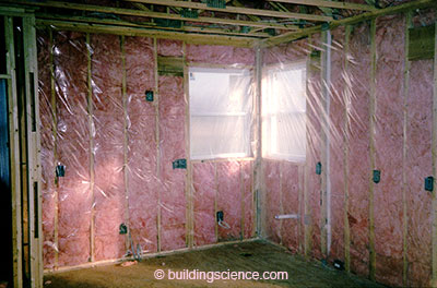
Photograph 1: Plastic Vapor Barrier—Not a “production friendly” method of achieving airtightness and it was not “robust” in terms of surviving the construction process and in providing performance over the service life of the building. It was also climate sensitive. It made no sense for assemblies that saw air conditioning – it was a vapor barrier on the wrong side of such assemblies.
The next step in the evolution of the air barrier was the “airtight drywall approach” (Figure 2) – where the interior gypsum board lining became the air barrier (Photograph 2). Sheet polyethylene was no longer necessary. The approach was more robust than polyethylene air-vapor barriers and since gypsum board was not a vapor barrier the approach could be used in any climate. However to get to similar extraordinary levels of airtightness as those being achieved with the poly approach in the R-2000 program painstaking effort was still required. Most production builders concluded such levels of airtightness were not worth the effort.
Photograph 2: Interior Gypsum Board as the Air Barrier—Note the sealant at the bottom plates an around window openings.
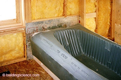
The focus shifted to targeting only the interior big holes using sealed rigid draft-stopping. Bathtubs and shower enclosures on exterior walls, fireplace assemblies on exterior walls, soffits dead ending in exterior walls, dropped ceilings at enclosure perimeters, garage-to-house connections and cantilevers (Photograph 3 and Photograph 4). A “lite” version “airtight drywall approach”. It became relatively easy for production homebuilders to get below 3 ach@50Pa and the approach morphed into the EPA Energy Star “thermal bypass checklist” and eventually found its way into the model codes5.
Photograph 3: Bathtub on Exterior Wall—Targeting the big holes with rigid draft-stopping. Of course an even better approach is not have a bathtub on an exterior wall…
Photograph 4: One-Piece Tub Shower Enclosures—A really, really big hole on an exterior wall sealed by a very happy builder. Note the sealant around the perimeter of the rigid draft-stopping sealing the draft-stopping to the framing.
But getting to 1 ach@50Pa if you were a production builder needed rethinking the problem. There were too many problems with locating the air barrier on the interior. Penetrations from electrical boxes, plumbing, intersecting interior walls and intermediate floor framing made very high levels of air tightness impossible for production home builders with interior air barriers. The focus shifted to the outside.
How about filling the cavities with an air barrier material-spray polyurethane foam (Figure 3 and Photograph 5)? However, in frame construction, spray foam is not continuous at all wood-to-wood connections, such as built up corners, window rough openings, and double top plates. These details need to be addressed.

Photograph 5: Interior Spray Polyurethane Foam-In frame construction, spray foam is not continuous at all wood-to-wood connctions. These details need to be addressed.
Why not turn the exterior building paper into the air barrier? Tarpaper was already being used for rainwater control purposes. Why not turn it into an air barrier? Good idea in principle, but tarpaper was not the product up to the task. You could not tape tarpaper and it only came in narrow rolls6. Plastic housewraps were developed and the exterior “air infiltration barrier”7 was introduced (Figure 4 and Photograph 6).

Photograph 6: Air Infiltration Barrier—Classic housewrap rainwater control layer and air control layer. Note the beautiful job of flashing integration with the housewrap. The outside is the right place for air control.
It was an amazing transformation in retrospect. Tarpaper was introduced first to control air and then it took on a rain control function. Its original air control function was forgotten when sheet goods like plywood and OSB replaced exterior (and very air leaky) board sheathing. Now the air control function was back. But to a production builder, the water control function was still more important. And for good reason, builders do not get calls in the middle of the night saying their buildings are leaking air, but they do get those calls when they are leaking rainwater.
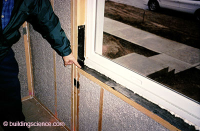
The “new” air infiltration barriers needed to be robust rainwater control layers. Numerous elegant and clever accessories were introduced to deal with rainwater control particularly at window-to-wall interfaces (Photograph 7 and Photograph 8).
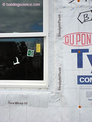
Photograph 7: Robust Rainwater Control—Numerous elegant and clever accessories were introduced to deal with rainwater control particularly at window-to-wall interfaces. This is a formable and flexible membrane “pan flashing” system.
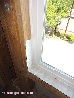
Photograph 8: More Robust Rainwater Control—Beautiful “under window gutter” where the pan flashing is sealed to the interior of the window unit for air barrier continuity.
But very high levels of airtightness were still elusive to production builders using exterior housewraps. They were difficult to work with – flexible films on the exterior proved to have similar issues to the experience with flexible films on the interior.
How about fully adhered membranes? Yup, they worked big time (Photograph 9). Ultra high levels of airtightness were achievable – but at ultra high levels of cost. This was a great commercial building enclosure technology that failed to get traction residentially mostly due to cost. They were not easiest thing to install either. There were also physics related issues. Until very recently no vapor open fully adhered membranes were available which meant that insulation need to be installed outboard of the membranes to control the temperature of the condensing surface during heating - the condensing surface being the interior of the exterior sheathing – typically plywood or OSB.
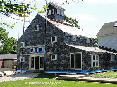
Photograph 9: Fully Adhered Membrane—Ultra high levels of airtightness with ultra high levels of cost. Not the easiest stuff to install either. I should know, this is my place.
On the commercial side fluid applied air barriers began to make inroads due to their competitive cost and relative ease of installation. It was only a matter of time before they appeared residentially (Photograph 10 and Photograph 11). Overcoming the technical challenges has not proven to be easy. The coatings needed to be able to span joints and they needed to be vapor permeable. And their most important function, rainwater control could not be compromised. After a decade of experience – principally on the commercial side – we are seeing products that are working. Origami is no longer a required skill to flash a window opening (Photograph 12 and Photograph 13)8.
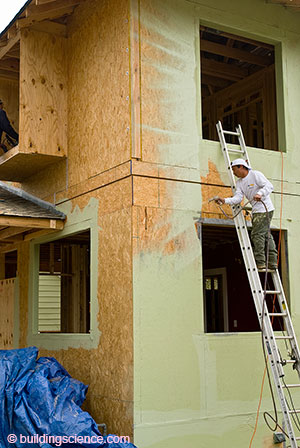
Photograph 10: Fluid Applied Air Barrier—The coatings needed to be able to span joints and they needed to be vapor permeable. And their most important function, rainwater control could not be compromised.
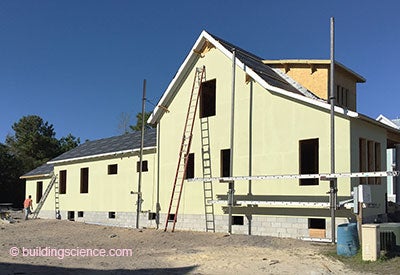
Photograph 11: Water Control/Air Control Continuity—The fluid applied coating must connect to the air control layer of the roof assembly and to the air control layer of the foundation assembly.
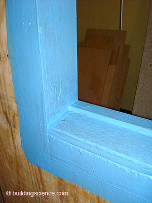
Photograph 12: Window Opening—Origami is not a necessary skill with fluid applied flashing systems.
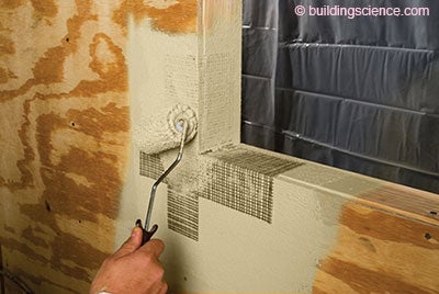
Photograph 13: Another Window Opening—Some systems require fabric reinforcement at critical interfaces.
What about turning the sheathing itself into both the water control layer and air control layer? Yes, see Photograph 14 and Figure 5. You could even have the sheathing be the thermal control layer (Figure 6 and Photograph 15).
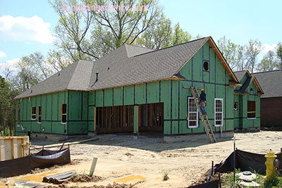
Photograph 14: Sheathing Water and Air Control Layer—The sheathing in this system is pre-coated with a water control layer. Tape is used provide water control and air control layer continuity.
Photograph 15: Insulating Sheathing Water and Air Control Layer—The insulating sheathing provides three functions in this approach – water control, air control and thermal control.
You still need to deal with the joints of course. Tapes are currently the technology of choice, but I see that changing. I see fluid applied joint systems replacing tapes – due to speed, cost, surface adhesion advantages and application temperature advantages (Photograph 16).
Photograph 16: Fluid Applied Joint System—Replacing tapes with fluid applied joint systems is now possible.
So where are we after 40 years? We went from the interior to the exterior with air barriers. And we went from combining the vapor barrier with the air barrier on the inside to combining the water control layer with the air barrier on the outside. We went from films on the inside to sheet goods on the inside. Then we went from films on the outside to sheet goods on the outside. We went from caulking and the black death on the inside to tapes and fluid applied joint systems on the outside. We are not done of course. But we are well on the way. It is only a matter of time that production builders move the airtightness bar from 3 ach@50 Pa to 1 ach@50 Pa.
References
Hutcheon, N.B.; “Fundamental Consideration in the Design of Exterior Walls for Building”, NRC Paper No. 3087, DBR No. 37. Division of Building Research, National Research Council of Canada, Ottawa, 1953.
Hutcheon, N.B.: “Forty Years of Vapor Barriers”, Canadian Consulting Engineer, special publication on Moisture Control, Ottawa, 1978.
Rowley, F.B., “A Theory Covering the Transfer of Vapor Through Materials”, ASHVE Transactions 45:545, 1939.
Footnotes
- This is a play on the title of Professor Hutcheon’s classic paper “Forty Years of Vapor Barriers”. Read down a couple of footnotes and enjoy…
- Hutcheon, N.B.; “Fundamental Consideration in the Design of Exterior Walls for Building”, NRC Paper No. 3087, DBR No. 37. Division of Building Research, National Research Council of Canada, Ottawa, 1953.
- At the turn of the 20th Century it became common to install a layer of rosin paper over wood board sheathing and under clapboard siding (see “BSI-033: Evolution”) to reduce drafts. This rosin paper was an early “air barrier”. Having pointed this out, I am going to conveniently ignore this fact because it messes with my narrative.
- It was 30 years from the time of Rowley’s paper before it was clearly established and widely accepted that the leakage of air from inside a building through constructions and not vapor diffusion alone was often the principal means by which water vapor moved to cold surfaces. The concept of vapor diffusion was not wrong, but it was not the only way. It is incredible, in retrospect, that it should have taken so long to reach this conclusion…” N. B. Hutcheon, from “Forty Years of Vapor Barriers”, Canadian Consulting Engineer, special publication on Moisture Control, Ottawa, 1978.
- The 2012 IECC requires that homes in cold climates are constructed such that they are less than 3ach@50Pa and the “thermal bypass checklist” is prescriptively listed as a code requirement.
- And you couldn’t print advertising and logos on it to turn your building into a billboard.
- Tarpaper was originally introduced 100 years earlier to keep drafts out of exterior walls – hence the initial focus on “air infiltration” rather than air flow from both the interior and exterior.
Why not just get rid of the damn window? It is a big thermal hole in the wall. It leaks rainwater. It leaks air. It is expensive. My life as an engineer would be so much simpler. This of course is why we do not let engineers design buildings that people actually live in and work in. We need architects.