Claddings made of wood, fiber cement, stucco, concrete, and masonry all absorb water to varying degrees. Once the reservoirs get wet, the stored water can migrate elsewhere and cause problems. Therefore, reservoir claddings must be decoupled from water sensitive materials of the wall assembly.
As with any cladding in a water-managed assembly, drainage must be provided behind reservoir claddings. Drainage requires two things: 1) a drainage plane and 2) a drainage space (see Information Sheet 301 – Drainage Plane/Water Resistive Barirer).
Absorbed water migrates by capillary transport or changes to a vapor and migrates by air flow or diffusion. Therefore, in addition to drainage, reservoir claddings also require control layers for capillary water, airflow, and water vapor. A proper drainage plane will also provide capillary control (in addition to dealing with bulk liquid water). Air flow control is provided by an air barrier to the interior of the drainage space. This air barrier could also be the drainage plane if the drainage plane is an air barrier material installed in a continuous manner with all joints sealed. Examples of drainage planes that also function as air barriers include liquid-applied exterior vapor retarder/air barriers, fully adhered impermeable sheet membrane, and air impermeable insulating sheathing with all joints taped.
Water vapor control is particularly important for reservoir claddings that may be exposed to sunshine—even in predominantly heating climates. When absorbent cladding materials or retained water in the drainage space is heated by solar exposure, very large inward water vapor drives can result. These inward drives can cause dangerous summertime condensation within wall cavities, especially if a low-permeance vapor barrier (e.g., polyethylene) or finish (e.g. vinyl wall paper, mirrors, and cabinets) are used on the interior. There are two methods of controlling this vapor drive: 1) ventilate the cladding, and 2) provide a vapor control layer behind the cladding. These may also be used in combination for situations of elevated moisture loading.
Cladding Ventilation
For claddings with significant reservoir capacity, including masonry and fiber-cement, ventilation is recommended to enhance moisture control. Ventilation, or exterior airflow behind the cladding driven by wind pressure differences on the face of the building or solar heated air rising, is useful since it accelerates drying by removing moisture from the drainage space. Ventilation bypasses the high vapor resistance of claddings such as vinyl siding, metal panels, and cement board, thereby allowing outward drying of the wall assembly.
A clear space is required behind cladding to encourage ventilation. While effective drainage of rainwater can occur in drainage spaces as small as 1/16 to 1/8 inch (e.g. between two layers of building paper in a stucco cladding), effective ventilation may require spaces as large as 3/4 to 1 inch depending on the moisture load (e.g. between a brick veneer and a building wrap). The greater the reservoir, the greater the moisture load, and the greater the ventilation required. Keeping the ventilation space clear may be challenging with masonry claddings such as brick veneers. It may be worthwhile to specify a wider ventilation cavity if quality control measures are not sufficient to keep mortar droppings from closing or constricting the ventilation space.
Effective ventilation also requires placement of clear vents at both the top and bottom of the wall. This will maximize the stack potential and hence the motive force to promote ventilation. Vent holes are also needed at horizontal interruptions of the wall such as window sills and heads.
Vapor Control Layer
Another method of controlling inward vapor drive is to use a vapor control layer, or vapor retarder in conjunction with—or as the weather resistive barrier or sheathing layer. Even with ventilated cavities, additional control is often required to control inward vapor drives, and an outer layer with moderate or low vapor permeance (such as foam sheathings or thin-profile structural sheathing) is recommended. An example is shown in a diagram below.
The degree of vapor control required is determined by the moisture loading, water sensitivity of materials, and inward drying potential. Care must be exercised to avoid using an exterior-side vapor retarder that interferes with outward drying where such is needed.
In cases of limited inward drying potential and water sensitivity of the assembly, robust control of inward vapor drive may be required. A reservoir cladding can also be uncoupled by providing a condensing surface such as an impermeable insulating sheathing or by using a fully adhered sheet membrane that is also impermeable (i.e. also a vapor barrier). This is a particularly attractive approach where it is not possible or practical to provide a cavity (“ventilation space”) free from mortar droppings.
Reservoir Claddings Details
Figure 1
Inward Moisture Movement Due to Solar Radiation
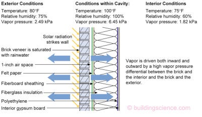
- Absorptive claddings such as brick veneers, when used over a vapor permeable combination of exterior sheathing and weather-resistive barrier should have a ventilated cavity and high inward drying potential (i.e. no polyethylene vapor barriers).
- A ventilated cavity will both reduce inward driven moisture and increase drying to the exterior.
- An outer layer with moderate or low vapor permeance is recommended to control inward vapor drive.
- Vapor barriers such as polyethylene film, vinyl wall coverings, or foil-backed cavity insulation should not be installed on the interior side of air conditioned assemblies.
Figures 2A and 2B
Ventilated Cladding
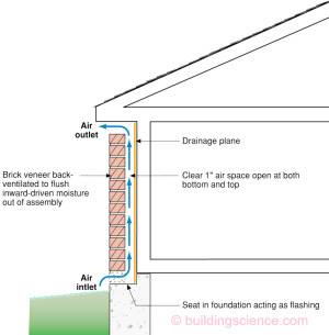
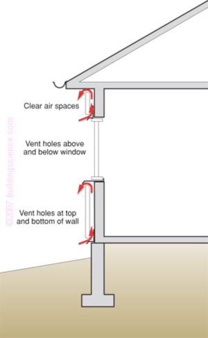
- To effectively uncouple a reservoir cladding from a wall system by using back ventilation, a clear cavity must be provided along with both air inlets at the top and bottom of each wall section.
Figure 3
Drained Cavity with Condensing Surface
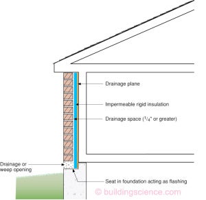
- To effectively uncouple a brick veneer from a wall system by using a condensing surface, the drainage plane must also be a vapor barrier. Alternatively, a vapor impermeable layer can be installed between the drainage plane and the brick veneer.
- Note the impermeable or foil-faced rigid insulation can be configured to perform as both the drainage plane and the vapor impermeable layer
- When a condensing surface is used to uncouple a brick veneer from a wall system, a ventilated air space is no longer necessary.
Figure 4
Stucco with Drainage Plane and Drainage Space
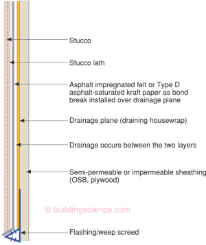
- Stucco applied over water sensitive materials must be uncoupled from the water sensitive materials. This can be accomplished via drainage and a capillary break.
- For drainage to occur, both a drainage plane and a drainage space are required. Therefore, the stucco must not bond continuously to the drainage plane, a bond break is necessary.
- The capillary break can be an airspace, foam sheathing or the drainage plane material itself
- Semi-permeable or impermeable sheathing provides control of inward vapor drive.