A homebuilder in the New England area has been building net zero energy single family homes since 2008 and is continuing with multiple small-scale subdivisions of 20 or more homes. This builder specializes in net zero affordable homes and sustainable net zero communities, while retaining houses with a familiar local vernacular appearance. The builder also has been concentrating on cost control for these houses, given the shift into full-scale production. Energy modeling and analysis have also been used to examine the cost-effectiveness of various options. Avenues examined have included various solar domestic hot water systems, building-integrated photovoltaics, modifications to the wall construction, and modified foundations.
Introduction
A homebuilder working in the New England area has been building net zero energy single family homes in Massachusetts since circa 2008, and is currently continuing with multiple small-scale subdivisions of 20 or more homes. This builder specializes in net zero affordable homes and sustainable net zero communities, while retaining houses with a familiar local vernacular appearance. These homes range from 1100 to 2600 square feet (100 to 240 m2) of finished floor area, with one or two stories, foundation types include both slab-on-grade and unfinished basements.
Some of the key features of these houses include solar orientation, superinsulated double-stud above grade walls (R-45+ / 7.9 m2K/W nominal), triple glazed low emissivity krypton-filled windows, and exceptional airtightness. The mechanical design takes advantage of the reduction in enclosure-based heating loads by using single-point (or one point per floor) heating, in the form of mini-split or ductless split air source heat pumps. Domestic hot water is supplied by a condensing tankless water heater. All homes have roof-mounted photovoltaic arrays.
The predicted annual output of the photovoltaic systems equals the predicted annual energy consumption of the houses, on a source energy basis, making these homes net-zero or near net-zero consumers of energy (modeled HERS Indices between -3 and +4). The design is a grid-tied net zero source energy building (as defined by Torcellini et al. 2006), meaning that fossil fuels are burned on site, and excess renewable energy is generated to offset this use. Therefore, when measured in terms of source energy, renewable energy produced at the building site offsets all energy consumption of the building,
Utility bill data were collected for one all-electric home: over one year it had near-net zero energy consumption (net annual energy consumption was 1000 kWh / 3600 MJ). More recently constructed homes have larger solar arrays, and use natural gas for water heating. It is therefore very likely that these houses will produce more energy than they consume, on a source energy basis.
Building Characteristics
Building Enclosure
The building enclosure characteristics, including insulating values, are described in Table 1 below.
Table 1: Building Enclosure Characteristics
All R-values in ft2•°F•h/Btu; CFM 50=cubic feet/minute @ 50 Pa; ACH 50=air changes/hour @ 50 Pa
The use of low-density (0.5 lb/cu. ft.; 8 kg/m3) urethane spray foam (rather than cellulose) in a double-stud wall is not common practice. The foam selected provides a higher R-value (3.7/inch; 0.039 W/m-K) relative to damp-spray cellulose (R-3.5/inch; 0.041 W/m-K). More importantly, spray foam has more effective air sealing characteristics relative to cellulose. In the regions of Massachusetts where this builder is active, this low-density spray foam is available for nearly the same installed cost as cellulose, despite the former’s superior performance. However, recent price instability for spray foam has resulted in the builder evaluating the use of the interior drywall or the exterior structural sheathing as an air barrier. Either or both would be attractive options if the cost of spray foam rises substantially.
In general terms, double stud walls have a higher risk of moisture-related damage than conventional construction. The high insulation value results in colder temperatures at the exterior sheathing, leading to higher average moisture content. This risk can be mitigated by reducing wetting potential from the interior, and by increasing drying potential at the exterior (see Lstiburek 2010). In these houses, the risk of interstitial condensation (interior wetting potential) is reduced by the use of exceptional airtightness, as well as some interior vapor control (Class III vapor retarder - latex paint on gypsum board). A Class III vapor retarder also allows drying to the interior under favorable conditions. The exterior is clad with vinyl siding, which is an intrinsically self-ventilated cladding, allowing ventilation drying of the assembly.
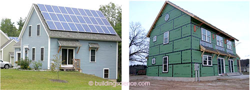
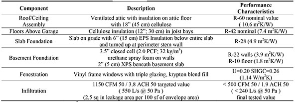
Figure 1: Completed house example (left), and house under construction, showing exterior air barrier approach (adhesive tape sealed seams on exterior sheathing) (right)
Air leakage measurements of these houses consistently show less than 500 CFM 50 (cubic feet per minute at 50 Pa test pressure), or 1.3 square inches EqLA (Equivalent Leakage Area, Canadian General Standards Board/CGSB (1986), calculated at a 10 Pa pressure differential) per 100 sf of enclosure area. (240 L/s at 50 Pa; 8.4 x 10⁻⁴ This is about 1.9 ACH 50 (air changes per hour at 50 Pa test pressure) for houses of median size. Several houses were tested at below 200 CFM 50 (1.2 ACH 50; 94 L/s at 50 Pa) through more careful attention to penetrations and detailing interior drywall or exterior sheathing as an additional air barrier.
Mechanical Systems
Most of the builder’s houses are heated using mini split air-source heat pump units. One of the earlier houses used concealed heads mounted in a dropped part of the ceiling, with a small ductwork system to distribute heated air. However, most of the houses use two wall-mounted ductless split heads (one per floor), eliminating the minimal ductwork system. The heat pumps used in recent work are systems documented to 90-100% of their nominal heating capacity at exterior temperatures of 5° F (-15° C) , which addresses one of the primary concerns of using air-source heat pumps in cold climates. For reference, the 99.6% design temperature for these regions of Massachusetts is in the range of 2° F to 7° F (-14° C to - 17°C).
A full-ducted central system of similar capacity would require ductwork sufficient to handle roughly 800 CFM (380 L/s) of airflow. Several builders in New England report that such systems have an installed cost premium of roughly $3000 relative to mini split installations. This is the primary motivation reported for installing these systems; some builders and buyers also favor heat pumps in order to reduce fossil fuel combustion within the house (and associated IAQ risks) and/or to increase utilization of site-generated electricity.
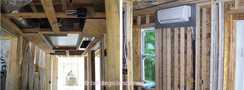
Figure 2: Minimally-ducted mini split mounted in dropped ceiling space (left) and single-point wall-mounted ductless split indoor unit (right)
Hot water is provided either by a tankless condensing gas water heater or by an electric heat pump. The gas system is expected to offer higher efficiency, but some homes are located far from gas mains. The analysis of these tradeoffs, and the ongoing study of heat pump water heater performance, are discussed below.
Earlier homes were built with a heat recovery ventilator (HRV) drawing air from one bathroom and supplying to the second floor hallway. However, due to concerns on ventilation distribution and the high installed cost of these systems, alternatives are currently being researched, as discussed below.
Research Topics
Under the auspices of the Department of Energy’s Building America Program, the authors are conducting further ongoing research into some of the topics which would improve performance, economics, and/or market acceptance of the houses being built by this builder. The topics discussed here include single point space conditioning systems, alternate ventilation systems, fuel choices in net-zero (or near net-zero) houses, and overall net zero performance of construction to date.
Single Point Space Conditioning Systems
As described above, the mechanical design takes advantage of the reduction in enclosure-based heating loads by using single-point (or one point per floor) heating. The common concern would be whether a single point per floor could maintain even distribution of comfort conditions in a cold climate—even with a highly insulated, airtight enclosure. To date, the occupants of these houses report a high degree of comfort, and all are unaware of (or are not bothered by) the temperature variations within the house. In recommending operational strategies for two-point heating systems, the authors were guided by data from earlier research on single-point heating (Fang 2009).
That research examined performance of single-point heating using sealed-combustion gas heaters on the first floor of a two-story residence, located in Western Massachusetts. A 90 CFM (40 L/s) fan moves air from the first floor to the second floor bedrooms continuously. Year-long temperature data indicate that comfortable temperatures are generally maintained. However, rooms distant from the heating source are slow to recover from thermostat setbacks (Aldrich 2010). Since daily setbacks save little energy in superinsulated houses, it was recommended to the builder and homeowners to set the thermostat for a constant temperature. They were also advised to leave doors to unoccupied rooms open to permit air movement and thermal distribution.
Calculation of heat transfer within the building confirm that only moderate temperature differences would occur even at the extremes of local weather. Heat transfer through uninsulated interior walls and floor is quite significant. At 5°F outside (MA 0.4% design condition; -15° C) and 72°F (22° C) in the hallway, the bedrooms would reach equilibrium at a temperature of 5° F to 10° F (3° C to 6° C) below the temperature of the directly heated space. In practice, a prolonged period of outdoor temperatures below 5°F is extremely unlikely in these climates. Most of the time, the equilibrium temperature difference will be less than those extremes calculated above, and bedroom doors will not be closed for sufficient time for the rooms to reach equilibrium. The builder at one point considered installing an air distribution system to equalize temperature between rooms. Calculations indicated that such a system would need to be prohibitively large in order to significantly change the temperature distribution.
In the fall of 2010, the authors installed data collection equipment in one occupied house. This house has three bedrooms on the second floor, a 1-ton (12,000 Btu/hr; 3.5 kW) ductless split heat pump in the second floor hallway, and a 1-ton ductless split on the first floor. Sensors were installed that measured temperature and relative humidity in each bedroom, the hallway, and the first floor; additional sensors measured duty cycles for both mini splits, and times at which the bedroom doors are opened and closed.
From these data the authors expect to learn how much the bedroom temperature deviates from the hallway temperature when the bedroom doors are closed, and by how much this exceeds the temperature difference with doors open. Logging the operation times of the heat pumps will reveal the lag between operation and bedroom response. These sensors will also provide general information about the house performance, notably the warmest temperature at which heat is required (balance point), and the temperature at which full capacity is required. Data from this monitoring will be collected at the end of the heating season.
Ventilation Systems
As discussed previously, earlier houses were built with an HRV exhausting from and supplying to single points (bathroom and second floor hallway). However, the builder became concerned that this system did not distribute the ventilation air, and in particular did not direct outdoor air to the bedrooms, where the highest pollutant concentrations typically occur. The bedrooms have air transfer grilles above the doors, and the doors are cut at least ½” (1.3 cm) above the carpet. These measures permit air to enter or leave the room; however, the lack of mechanical air supply means that there is no driving force. One possibility considered was to install a separate fan with ductwork to draw air from the hallway and supply it to the bedrooms. However, this represents a substantial duplication of materials and expense. The preferred option was to eliminate the HRV, and use the distribution system to draw air from outside directly.
Figure 3: Installed HRV (left) and schematic of proposed supply-only system (right)
In this ventilation system, a small fan is used to draw air from outside and from the three bedrooms, and deliver the mixed air to the hallway. This ensures air movement between the bedrooms and the rest of the house; and by mixing (at roughly 25% outside air) avoids the extremes of supply temperature. Supply ventilation systems are preferred to exhaust systems because the air entering the house comes from a known location, distant from the garage or other pollutant sources. The fan is substantially less expensive than a reasonably efficient HRV, and the ductwork is much less than a system designed to also provide space conditioning.
ASHRAE Standard 62.2 (ASHRAE 2007) calls for 50 CFM (24 L/s) of ventilation air, supplied continuously, for 2000 square foot (190 m2) houses with three bedrooms. However, anecdotal evidence suggests that when air is well distributed, most occupants are comfortable at rates 1/3 this. This reduced ventilation rate is easily achieved by operating a 50 CFM system for 20 minutes out of each hour (33% duty cycle). Assumptions about ventilation rate can significantly affect cost effectiveness of ventilation system upgrades. . .
Download complete document here.