To characterize outside air distribution in residential buildings, this paper develops a practical methodology adapted from ASHRAE Standard 129. The methodology includes the examination of multi-zone single tracer gas decay curves, and the calculation of reciprocal local mean age-of-air to allow direct, quantitative comparisons of various ventilation approaches that might be factored into ventilation rate trade-offs in future updates to ASHRAE Standard 62.2. Two types of ventilation systems were tested using this method: single-point exhaust ventilation and central fan integrated supply ventilation. Analysis of the measured data showed that age-of-air analysis worked well to characterize outside air distribution as long as weather conditions were sufficiently steady-state.
Introduction
In addition to the whole house ventilation rate, the minimum amount of outside air that should be provided to individual rooms in a house has been an important area of debate among ventilation experts for many years. Residential ventilation standards in numerous European countries, including Belgium, Denmark, Finland, Germany, Italy, The Netherlands, Norway, Sweden, and the United Kingdom, specify minimum ventilation requirements in bedrooms, living rooms, or both (McWilliams and Sherman 2005). In the United States, ASHRAE Standard 62.2 (ASHRAE 2004), Ventilation and Acceptable Indoor Air Quality in Low-Rise Residential Buildings, specifies an acceptable minimum whole-house ventilation rate that depends on the timing of ventilation air delivery; however, it is silent about distribution of ventilation air. The Washington State Ventilation and Indoor Air Quality Code (WAC 2004) is also silent about ventilation air distribution. Both the Minnesota Building Code (MN Chapter 7672) and the National Building Code of Canada (NBC 2005), which refer to Canadian Standard F326-M91 (CSA 2005), require whole-house ventilation air distribution via a fully ducted ventilation system or by mixing via a central air-handling system. A large, U.S. private-sector, high-performance home program also requires periodic air handler operation to ensure whole-house mixing for ventilation air distribution and thermal comfort. Work by Rudd and Lstiburek (2000) showed that ventilation systems that used whole-house distribution and mixing via the central air-handling system had much less room-to-room variation in outside air delivery than other tested systems that did not.
One way for dilution ventilation systems to provide a predictable minimum amount of fresh air to all rooms, regardless of house geometry and the behavior of occupants, is to uniformly distribute outside air throughout the house. The primary purpose of this research project was to develop a practical field test methodology to characterize such distribution of outside air in a house under various operating conditions, irrespective of the overall desirability of uniform outside air distribution, which remains an unresolved issue even among experts in the field. We endeavored to be fully consistent with ASHRAE Standard 129 (ASHRAE 1997), although it was necessary to adapt this standard to residential buildings because it was developed with commercial buildings in mind. The standard includes what we believe are overly strict criteria for acceptable test spaces in a residential context where infiltration is an important component of the outside air reaching a zone, and it requires measurements in exhaust and supply flows that are inapplicable and impractical in most residential situations. A multi-point single tracer gas decay procedure was chosen for this project because of its relative simplicity compared to a multi-gas system, recognizing that even a single tracer gas system is too costly for most home energy efficiency practitioners. For this study, we assumed that dangerous pollutant sources such as radon are controlled with appropriate source mitigation strategies, and that remaining low-level pollutants are uniformly generated in proportion to volume throughout the house. The tests were designed to allow direct, quantitative comparisons of various ventilation approaches, which might be factored into ventilation rate trade-offs in future updates to ASHRAE Standard 62.2. We did not attempt to develop a specific figure of merit, such as the air-change effectiveness defined in ASHRAE Standard 129, which is more suitable for commercial buildings.
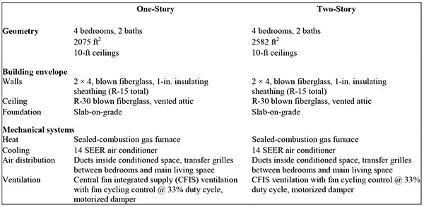
To evaluate the usefulness and practicality of this methodology, the distribution of outside air in two new houses in Sacramento, California, were evaluated using several different ventilation system configurations and air-mixing scenarios. The test program was conducted in late December 2005 and early January 2006, during relatively mild winter weather conditions. The first test house was a one-story model with four bedrooms. The second was a two-story model, also with four bedrooms. Both houses were part of the U.S. Department of Energy’s Building America program, and were designed to be much more energy efficient than typical new California houses. Each house had a slab-on-grade foundation with ducts located in conditioned spaces, and had a very tight envelope as measured with a blower door (less than 1.25 in2 equivalent leakage area per 100 ft2 envelope area). Because the building envelopes were tight for these houses, we expected less interaction between ventilation and infiltration than we would observe in leakier houses, and conclusions must be interpreted in that context. The minimum acceptable ventilation rates specified in ASHRAE 62.2 were 58 cfm for the one-story house and 63 cfm for the two-story house. Other key specifications for both houses are summarized in Table 1. Floor plans are shown in Figures 1 and 2. The results of this research have been documented in a more complete, unpublished field test report that is available upon request from the authors.
Table 1: Specifications for the One-Story and Two-Story Test Houses
Test Methodology
Test and Analysis Procedure
Because outside air distribution is a multi-zone problem, a single-tracer gas decay test with multi-zone sampling was used to evaluate the performance of each ventilation system based on how uniformly outside air was distributed to each of six well-mixed zones within the house. The decay curves demonstrate the rate at which the tracer gas (representing a pollutant), which is initially distributed uniformly throughout the house, is diluted within each zone, as a result of outside air that enters the zone directly as well as air that is exchanged among zones. Air entering one zone from another may contain either a higher or a lower concentration of the tracer than the air already in the zone. The initial decay rate represents the rate of dilution only from direct outside air supply to the zone, because other zones begin at the same concentration. The decay rate over a longer period is a result of dilution from outside air entering either directly or via air exchange with other zones, including the effects of outside air provided by both mechanical ventilation and natural infiltration.
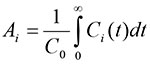
We used a version of local mean age-of-air analysis that we modified for this application to evaluate the results more quantitatively. Age-of-air analysis is a well-established approach for characterizing ventilation at various points within an initially well-mixed test space, which in our case is the whole house (Grieve 1991). Although the Grieve publication was written in the context of multi-zone tracer gas testing within a single room in a commercial building, we believe the same methodology applies to a house or other multiple room test space, as long as the initial conditions can be established with the test space beginning at a uniform concentration and outside spaces at zero concentration. Age-of-air is defined as the average length of time air molecules have resided within the test space. Age of air calculations are a characteristic of the house and ventilation system under specific weather and operating conditions, and are valid regardless of the eventual distribution of source pollutants in the house. However, because age-of-air is independent of the pollutant sources, it cannot be used to predict exposure except in the limiting case of uniform pollutant generation. The formula for calculating local mean age-of-air in a tracer gas decay test is given in both Grieve and ASHRAE Standard 129-1997 (ASHRAE 1997) as follows:
 (1)
(1)
where:
i = Index for measurement point
Ai = Local mean age-of-air at point i (h)
C = Concentration of tracer gas (lbm/ft3)
C0 = Initial value of C in a well-mixed building (lbm/ft3)
Ci = Time-varying concentration of tracer gas at point i (lbm/ft3)
t = Time (h).
To compare individual zones in this test, the primary metric used by NREL was the reciprocal of the local mean age-of-air (from this point forward referred to simply as reciprocal age-of-air) at a central point in each well-mixed zone:
Reciprocal age-of-air = 1/Ai (2)
Reciprocal age-of-air has units of 1/h and would be equivalent to the air change rate in units of air changes
per hour (ACH) for the limiting case when the house behaves as a single, well-mixed zone. Its precise physical
meaning is difficult to put into words, but we believe it is a good indicator of the rate at which outside air is
provided to a zone. The definition of Ai in Equation 1 involves an integral of infinite duration. This was handled in
the test procedure through a two-step process:
Step 1. The tracer gas decay test was continued until (a) the initial transient effects of interzonal airflow have subsided and all the decay curves resembled simple exponential functions, and (b) the tracer concentrations
were rather small compared to their initial values, so that any extrapolation errors would have a minimal effect on
the result. These portions of the decay curves were integrated numerically with the trapezoid rule applied to actual measured data.
Step 2. The remaining portions (the tails) of the decay curves were extrapolated to infinity with a simple exponential decay function, which was matched to the decay rate of the final portion of each measured decay curve. These portions of the curves were integrated analytically. This extrapolation can be prone to significant errors if there are unsteady operating conditions, such as occasional cycling of the air handler. A larger data set is required in such cases.
The test equipment consisted of a tracer gas monitor and a multi-point sampler. Sample tubes were placed in six locations in each house and attached to the multi-point sampler. The six sampled locations are designated with red stars on the floor plans in Figures 1 and 2, and each represents a well-mixed “zone” as defined in this paper. The air sample in each zone was taken near the center of the zone at a height of 4 feet above the floor. The zone air temperature was measured at the same location. The sampler was programmed to draw a sample from each sequential location at an interval of about 2 minutes; thus all six locations were sampled at an interval of about 12 minutes. The local zone air temperature measurement was used to control an electric heater in each zone to achieve a uniform and constant air temperature throughout the house. Small mixing fans were used to maintain uniform temperatures and tracer gas concentrations within each zone, so that the sampled point would represent the room average concentration that would occur under normal operating conditions. Natural infiltration rates varied during the tests depending on weather conditions, which were monitored with a portable weather station. The tests were planned for rather mild weather to minimize infiltration effects, allowing us to more easily isolate and test the performance of the mechanical ventilation systems.
The air flow rates for supply and exhaust ventilation were carefully controlled during the test with a ducted, calibrated, variable-speed fan and measurement system of the type often used to measure duct leakage. For exhaust ventilation, the variable-speed fan was placed near the ceiling exhaust fan and a length of flexible duct was used to connect the normal register for the exhaust fan to the duct for the variable-speed fan. The exhaust fan was operated in conjunction with the variable-speed fan to reduce resistance to air flow. A similar application of the calibrated variable-speed fan was used to control and measure the supply air flow rate during the tests of the central fan integrated supply (CFIS) system. The normal configuration of flexible duct connecting the air handler return to the outside was changed so that all outside air would flow through the variable-speed fan.
The tracer gas used was sulfur hexafluoride (SF6), a stable, nontoxic gas that was injected into each house from a small compressed gas cylinder carried by hand around the house. During the dosing period, the air handler was used to achieve an initially well-mixed condition with a concentration of about 15 parts per million (ppm). During this period, the doors were kept open and a portable destratification fan was used in the two-story house to improve mixing between floors. Once well-mixed conditions were achieved, the air handler and destratification fans were stopped and the ventilation conditions of interest were established. The divergence in concentration from zone to zone was then observed as the tracer gas decayed. At the conclusion of the test, the whole house was again mixed to the extent possible by opening the doors (if they were closed during the test) and turning on the air handler, allowing the effective whole-house air change rate to be calculated.
The results of the multi-zone tracer gas decay tests were plotted graphically as families of decay curves. If a test met the necessary criteria, we calculated reciprocal age-of-air based on the decay curves and examined the results. These criteria included uniform initial concentration, steady weather conditions (and therefore steady natural infiltration), steady operating conditions (except for the small effect of fan cycling), and all decay curves in the exponential regime at the end of the test period. . .
Download complete document here.