The owners of this single family Victorian had previously gone through a retrofit in the spring of 2009. The upgrades included adding closed-cell spray foam insulation to the underside of the replacement roof as well as to the existing field stone foundation walls. Work had been also done to modernize the radiant hydronic heating distribution system, which was originally steam. With the financial and technical support offered through National Grid’s Deep Energy Retrofit Pilot Program the owners decided to continue making the improvements to the house and incorporate a deep energy retrofit (DER) to the remaining parts of the house.
The present retrofit project for this home includes addition of exterior wall insulation and high performance triple-pane windows, air sealing to connect the new and previous retrofit measures, replacement of heating and water heating equipment, and provision of mechanical ventilation.
This home provides an example of a staged approach to a comprehensive retrofit. New retrofit measures are carefully thought out and integrated with the measures implemented previously. This staged approach may be a more realistically accessible path to broad adoption of DER. The nature of the retrofit work in this present phase of the larger project imposed minimal disruption to the interior.

Project Team: Synergy Construction, Builder and DER Lead; Building Science Corporation, Consultants and DER Technical Support; National Grid, Massachusetts, DER Pilot Program Administrator/Sponsor
Location: Brookline, Massachusetts
Description: 3,078 ft2 four bedroom, three bathroom, 2 ½” stories plus a full basement single family Victorian
Completion Date: November 2011
Estimated Annual Energy Savings: Projected 37% energy use reduction compared to pre-retrofit conditions
Design
To build upon the direction set by previous work, the current enclosure retrofit project for this test home focuses on the above-grade walls and windows. The existing composite of vinyl siding and original wood siding were showing signs of deterioration. The DER plan for this test home involved striping the above grade walls to the sheathing, repairing sheathing as needed, then establishing control layers to the exterior of the sheathing. Thus, even without the super-insulation measures, the wall retrofit significantly improved the performance and durability of the wall system.
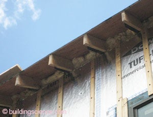
To provide generous protection for the walls and also to maintain the refined period aesthetics of the home, the plan also involved extending the roof eaves. The roof eaves had not been extended as part of the previous project in which the roof was addressed.
The project team and owners deliberated for some time whether to replace the windows. The existing windows had been installed relatively recently (within 5 years) and offered reasonable thermal performance. Ultimately the owners decided to replace the windows in order to provide for better integration with water management and to capture the incremental performance benefits.
The rather tall configuration of the home and the fact that the project did not include replacement of interior finishes presented a challenge to design of new distribution. Aesthetics, geometry of the house, cost as well as proper sizing of the units were the factors in the selecting the equipment and installation approaches. The owners considered adding cooling to the house but in the end they decided against it.
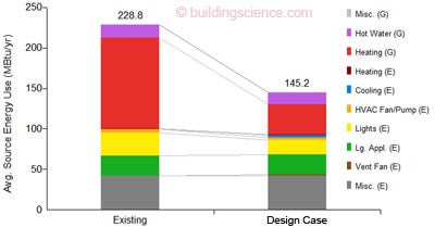
Parametric Study of Source Energy Use
(Image from BSC generated by NREL’s BEOpt 1.1 for retrofits)
Enclosure Design
Roof Assembly: Retrofit measures completed in the previous enclosure retrofit; R-48 (nominal): Unvented roof assembly with 8” of closed-cell spray foam between the rafters; ½” plywood; fully-adhered membrane; asphalt shingles.
Roof Assembly
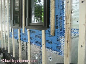
Wall Assembly: R-40 (nominal): Existing dense-packed cellulose insulation in wall framing cavities; housewrap over existing board sheathing, sealed at perimeter and all penetrations with seams taped; two layers of 2” foil-faced polyisocyanurate insulating sheathing; ¾” furring strips; wood siding.

Wall Assembly
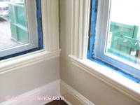
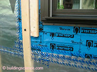
Window Specifications: New Paradigm triple-glazed, krypton/argon blend gas, low-E vinyl windows, U=0.20, SHGC=0.25; windows installed in alignment with drainage plane.
Window Specifications
Air Sealing: Sealant applied between housewrap and existing board sheathing at top and bottom of wall; sealant between successive layers at bottom of wall transitions airflow control to foundation airflow control of previous work; taped insulating sheathing with joints offset; two-part foam applied at the top of insulating sheathing to connect to closed-cell spray foam of previous work.
Air Sealing
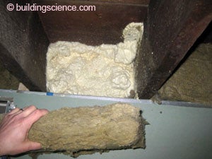
Foundation Assembly: Retrofit measures completed in the previous enclosure retrofit; 3” closed-cell spray foam applied directly onto the existing field stone foundation walls; gypsum wall board thermal barrier on 15/8” metal studs partially embedded in closed-cell spray foam; 7” closed-cell spray foam at sill beam with a layer of rigid mineral wool insulation; slab remained uninsulated.
Foundation Assembly
Construction
The builder demonstrated an innovative approach with the installation of the windows in alignment with the drainage plane of the wall. Wood blocking let in to exterior layer of insulation is covered by self-adhered flashing that wraps into the opening over the wood blocking and inner layer of insulating sheathing. Since the insulated sheathing used is 2” thick, the blocking is padded to the inside with 1⁄2” of rigid foam insulation. The blocking is fastened to the wall framing through the inner layer of exterior insulating sheathing. Positive drainage of the window sill pan flashing is established by cutting the foam at the bottom of the window to provide a slope. With the opening prepared, the window is installed and flashed as per typical practice with fasteners into the 2x blocking through the nailing flanges.
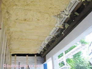
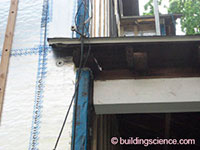
This project demonstrated robust means of maintaining continuity of the water, air and thermal control at attached porch roof and porch deck connections by temporarily supporting the structures, cutting them back from the wall, installing the air, water and thermal control layers, then re-attaching the structures over these layers. The continuous airflow control layers enabled by this measure likely contributed to strong air leakage reduction.
Mechanical Design
Heating: Buderus condensing boiler located in the basement for hot water radiators. The owners chose not to install cooling.

Wall-hung condensing boiler
Ventilation: Imperial Heat Recovery Ventilator (HRV) located in the basement. Ventilation supply ducted to living and dining room and hallways, stale air exhausted from bedrooms. Point source ventilation from kitchen and bathrooms.
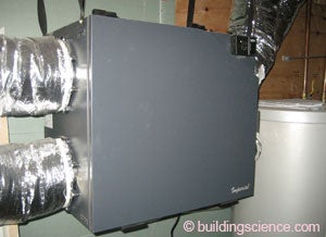
Heat recovery ventilator (HRV)
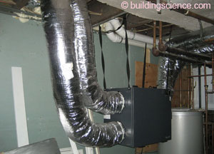
Space Conditioning Distribution: Ventilation ductwork and hydronic distribution located entirely within the conditioned space.
Space conditioning
DHW: SuperStor® Ultra hot water storage tank connected to the boiler located in the basement.
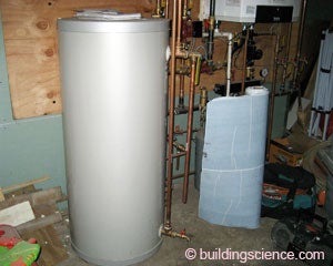
Water storage tank
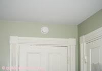
Lighting: Combination of CFL and incandescent light bulbs in light fixtures.
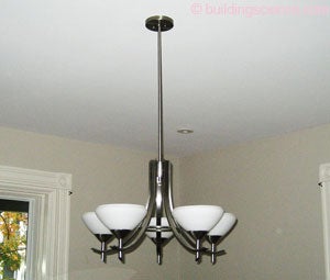
Light fixture
Appliances: Existing ENERGY STAR® appliances.
Testing and On-Site Technical Support
BSC was able to assist the builder with technical issues through both on-site visits and remote support. Ventilation strategies were discussed in order to work out the best approach for providing ventilation in this circa 1900 house. Aesthetics and geometry of the house played a significant role in selecting the right equipment and finishes as well as developing an appropriate approach for distributing the ductwork.
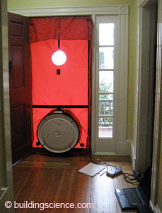
BSC performed a pre- and post-retrofit air leakage testing to determine the improvement in the air leakage of the whole house. The pre-retrofit air leakage measurement was 1657 CFM @50 Pa (3.80 ACH 50) and the post-retrofit measurement was 655 CFM @50 Pa (1.50 ACH 50).
Moving Forward
Monthly gas and electric bills will be collected from the homeowner to gauge performance of the retrofit strategies employed.
The builder for this project had completed several DER projects prior to this one and demonstrated acumen in developing various improvements in retrofit strategies. The builder continued to do so in the present DER retrofit project. Certainly, the retrofit approaches will keep evolving in the several future DER projects that are in store for the builder.
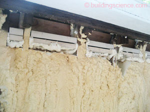
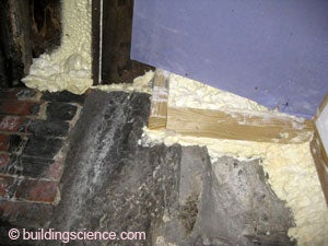
Design Challenge: Doubling Efforts This project presented interesting challenges of connecting the control functions of an exterior wall retrofit system to previous retrofit work. At the front of the building is an overhanging floor where the previous retrofit had applied closed-cell SPF. The exterior insulating sheathing added as part of the current retrofit was applied to the face of the wall and continuous through the location where the porch roof had been cut away. As seen in the photo to the right, the use of two-part kit foam does not appear to have successfully connected the new work to the previous work at the first attempt. A second application of two-part foam was needed to provide robust connections. |