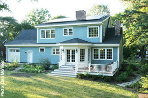
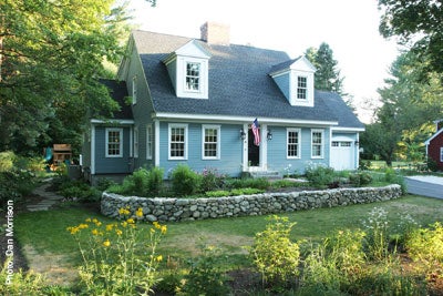
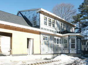
The design of the Concord Cape began in August of 2008. Architects and engineers at BSC developed the drawing set and specifications for the high performance custom home to be built in Concord, Massachusetts. The house is a Cape Cod style design with 5 bedrooms, 4 full bathrooms, 2 stories plus a finished basement. It is built into an existing neighborhood close to public transportation, restaurants, shops and other community resources. BSC worked closely with the homeowner to design a house that combined the desired design aesthetic, both interior and exterior, with high performance.
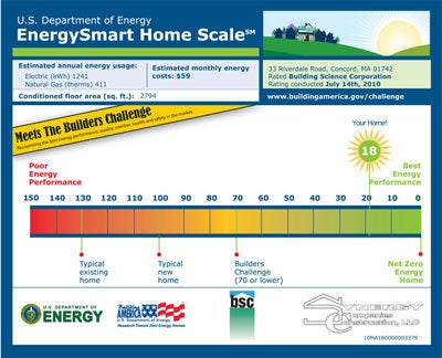
The house is designed to achieve an 87% reduction in source energy use when compared to the 2009 Building America Benchmark. This design features high-R walls, roof, and foundation along with a high efficiency mechanical system. Supplementing the high performance enclosure and mechanical system is a 7 kW PV array installed on the south facing roof. This 87% energy use reduction is equal to HERS 18 and a $4,700 annual utility bill savings to the homeowner.
The Concord Cape is not only part of the Building America Program, but is also registered in Builders Challenge and in USGBC’s LEED for Homes program, designed to achieve Platinum certification.
Project Team: Synergy Companies Construction, LLC, Minglewood Designs, Building Science Corporation
Location: Concord, Massachusetts
Description: 4,322 ft2 5 bedroom, 4 bath, 2-story plus finished basement single family home
Completion Date: June 2010
Estimated Annual Energy Savings: $4,700 per year (87% energy use reduction compared to the Building America Benchmark)
Project Website: www.concordcape.posterous.com
Design
Early in the design process, the project team worked to integrate the architectural, structural, and mechanical components into the plans and specifications. Various enclosure assemblies and mechanical systems were modeled. The models were then used as a tool in deciding which parameters were most cost effective and should be included in the project. See the Parametric Study for included measures.
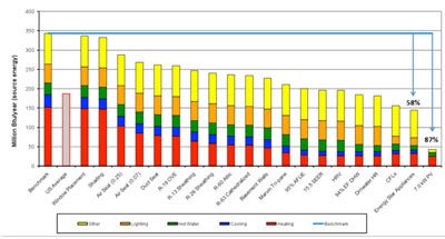
Parametric Study
Builders Challenge Certificate
In order to go above and beyond the goal of a 50% energy savings when compared to the Building America Benchmark, exceptional airtightness was specified. And in order to achieve this level of airtightness, multiple methods of air sealing were detailed in the drawings. These methods included the Airtight Drywall Approach for walls and ceilings, high density spray foam at rim joists, backer rod and sealant at windows and doors and taping the XPS insulation joints on the basement walls. For additional airtightness, the builder chose to also tape the foil-faced polyisocyanurate installed on the exterior walls. The actual tested airtightness (0.07 leak ratio) is represented in the parametric chart.
A highlight of the mechanical system design is the dual fuel heating system which includes both a heat pump as well as a high efficiency gas furnace. During the heating season, the heat pump is more efficient at milder outdoor temperatures while the furnace is more efficient at lower, colder outdoor temperatures.

Enclosure Design
Roof Assembly: Vented attic framed with engineered roof rafters at 24” o.c. over main house: R-60 cellulose at south side ceiling, R-63 at north side cathedralized ceiling (2” foil-faced polyisocyanurate rigid insulation between rafters and 7½” high density 2.0 pcf closed cell spray foam); unvented attic framed with dimensional roof rafters at 24” o.c. over breakfast area and dormers: R-63 high density 2.0 pcf closed cell spray foam.
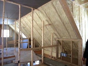
High-density spray foam
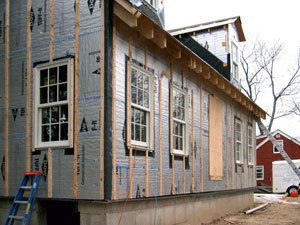
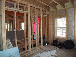
Wall Assembly: 2x6 wood stud walls at 24” o.c. with R-45 wall insulation: cellulose (R-19), 4” foil-faced polyisocyanurate insulating sheathing (R-26), ¾” furring strips and fiber cement siding installed on exterior, ½” drywall installed on interior.
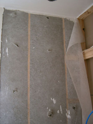
2x6 @ 24" o.c. framing with cellulose insulation
Window Specifications: Marvin Windows and Doors double-hung, triple pane, spectrally selective, Low-E: U=0.24, SHGC=0.23.

Window installed
Air Sealing: Maximum 0.15 CFM50 per ft2 of enclosure area. Spray foam at rim joist and breakfast area and dormer roofs, airtight drywall approach used in wall assembly, taped XPS insulation on basement walls. Adhesives and sealants used between framing members, around windows and doors, and at all mechanical and electrical penetrations through the enclosure.
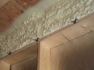
Spray foam as air seal
Foundation Assembly: 2” XPS (R-10) and stud wall with fiberglass batt insulation (R-12) installed on wall, 2” XPS (R-10) installed below slab.
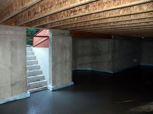
XPS sub-slab insulation
Construction
Before construction began, BSC held a pre-construction meeting with the builder, client, and LEED for Homes Provider. The purpose of this meeting was to review the drawing set to ensure all team members understood the design intent as well as how the design details affected house performance and third-party certification goals. Third-party certifications included LEED for Homes, ENERGY STAR® and Builders Challenge.
During the 10-month construction period, the project team visited the site regularly to answer questions from the builder and to document construction. The Durability Checklist, a document created during design, was used during each site visit to ensure critical details were being implemented. The checklist addressed items including water management, air barriers, mechanical system installation, landscaping and pest control. BSC conducted a walk-through with the homeowner and the builder to review the systems in the house to ensure it would be operated as designed to achieve maximum energy savings. A Homeowner’s Manual was also given to the homeowner to use as a reference should any questions arise.
Mechanical Design
Heating and Cooling: 95% AFUE gas furnace and 3-ton 8.2 HSPF/15.5 SEER heat pump split system with hybrid heat.
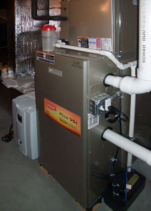
Gas furnace
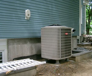
Outdoor condensing unit
Ventilation: Heat recovery ventilator (HRV) balanced ventilation system.
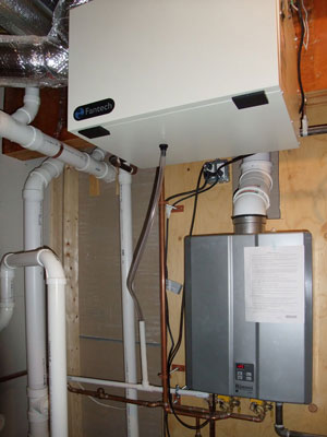
DHW: 0.94 EF gas condensing tankless water heater with drainwater heat recovery.
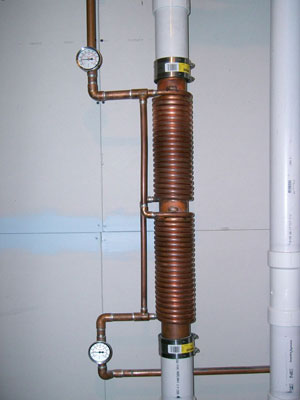
Drainwater heat recovery
Local Exhaust Ventilation: Intermittent spot exhaust provided in bathrooms and kitchen.
Space Conditioning Distribution: Two zone system with sheet metal trunks and run-outs located in conditioned space. Ducted return from entry hall and master bedroom with transfer grilles above bedrooms doors.
Thermostat: Programmable thermostat
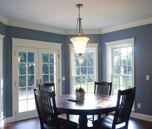
Lighting: All CFLs in light fixtures
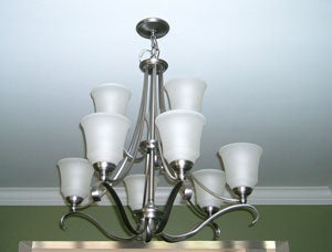
Light fixture
Appliances: All ENERGY STAR® appliances
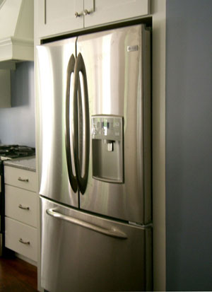
ENERGY STAR® refrigerator
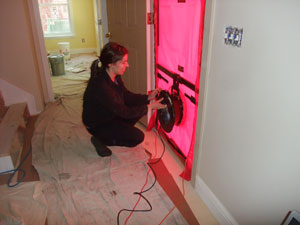
Testing
Concord Cape performance testing was done at both the rough-in stage as well as after construction was complete. At the time of the rough-in testing, the following had been installed: all windows and doors, high density spray foam at rim joists and unvented roofs (breakfast area and dormers), second floor ceiling drywall, taped exterior insulation, sheet metal ductwork and mechanical equipment in the basement. The blower door test result was 1019 CFM50, which is equal to 0.13 CFM50 per ft2 of enclosure area and 1.44 ACH50. Even before the Airtight Drywall Approach was implemented on the walls, the Concord Cape met the specified airtightness. Final performance testing revealed an even more airtight house with the following blower door test results: 505 CFM50, equal to 0.07 CFM50 per ft2 of enclosure area and 0.72 ACH50. Duct leakage to outside was measured at 18 CFM25.
Moving Forward
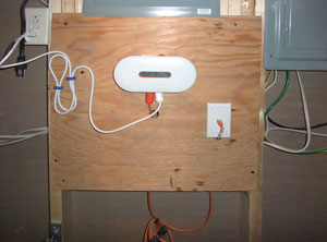
BSC is planning to collect monthly gas and electricity bills from the homeowner for at least one year. Actual energy use will then be compared to predicted energy use. In addition to the utility bills, the team will install and monitor a comprehensive circuit-by-circuit home energy monitoring and management system. The system displays electricity use by individual circuit so you can see real-time and historical information on specified circuits including major appliances, heating and cooling equipment, home offices and entertainment areas.
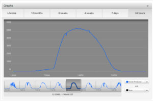
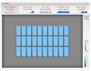
Design Highlight: 7 kW PV Array with Microinverters
|