This Measure Guideline provides design and construction information for a deep energy enclosure retrofit (DEER) solution of a flat roof assembly. It describes the strategies and procedures for an exterior retrofit of a flat, wood-framed roof with brick masonry exterior walls, using exterior and interior (framing cavity) insulation. The approach supported in this guide could also be adapted for use with flat, wood-framed roofs with wood-framed exterior walls. This Measure Guideline demonstrates techniques for retrofitting flat roofs from the exterior, which is less disruptive to the living space and allows the structure to remain occupied during the project. It also illustrates a solution for preparing homes to become zero energy ready.
1 Introduction
This Measure Guideline provides design and construction information for a deep energy enclosure retrofit (DEER) solution for a flat roof assembly. It describes the strategies and procedures for an exterior retrofit of a flat, wood-framed roof with brick masonry exterior walls with the use of exterior and interior (framing cavity) insulation. The approach in this guide could also be adapted for use with flat, wood-framed roofs with wood-framed exterior walls.
An exterior retrofit is generally more favorable than an interior retrofit because it is less disruptive to the living space and typically allows a structure to remain occupied during the project. Exterior retrofit also offers significant advantages for building durability by reducing the likelihood of cold weather condensation within the structure (Straube et al. 2012). This Measure Guideline includes several distinct sections that cover: a review of decision criteria pertinent to retrofitting flat roofs from the exterior, fundamental building science and design principles for the use of exterior and interior insulation, and construction detailing and procedures developed to explain how the various elements of the design are implemented.
Roof failures typically occur due to leakage of bulk water (precipitation), or vapor diffusion condensation. Most often, flat roof assemblies are designed and constructed without a proper air control layer, with focus only on the thermal control system (insulation). By designing the roof enclosure system properly, a majority of failures, if not all, can be avoided. A successful roof will perform the following tasks, per Straube and Grin (2010):
- Provide a water management system to keep precipitation out
- Provide an air barrier system between the indoors and outdoors
- Provide a vapor control system to maintain a durable environment that does not allow condensation and does not promote mold growth
- Provide a thermal control system to keep the heat out during the summer and retain heat during the winter
In the retrofit world, the order of work to be considered during construction or home improvements is important. Health and safety issues must be addressed first and are more important than durability issues, which are in turn more important than saving energy.
Designers, contractors, and building code officials will benefit from the information contained in this Measure Guideline. The guide may also be helpful to building owners wishing to learn more about strategies available for deep energy enclosure retrofit of flat roofs. For the most part, the use of this measure will be done as part of a larger building project and, therefore, it is highly recommended that a design professional or a qualified contractor be retained.
2 Decision Making Criteria
This section discusses the major decision making criteria once an exterior retrofit has been decided on, after considering issues such as aesthetics, historic significance, improved comfort, and the lifespan of the building, which tend to dominate the decision-making process to determine the type of retrofit to be undertaken.
Cost and Performance
Cost and performance are intricately linked and have to be studied in combination, to decide the best choice given the decision-maker’s goals and objectives. The decision on the thermal performance depends on the specific requirements of the project. For projects that would like to meet high-energy savings goals, a higher level of insulation must be provided.
The measure presented in this guide illustrates high levels of insulation; however, the decision on the amount of insulation to be added on the exterior and interior will depend on the existing structure of the roof, the locally adopted building and energy code requirements as well as the project budget. The Technical Description section of this Measure Guide discusses the building science principles as well as the requirements of the local building codes regarding the insulation levels for roof structures. Those requirements need to be met first. However, the homeowner may choose to increase the R-value of the roof assembly and a cost analysis may be performed to evaluate the payoff for the additional insulation.
The potential for thermal bridging must also be evaluated for the retrofit options under consideration. With the rigid insulation being installed on the exterior of the roof assembly, there will be very little thermal bridging. This allows for the nominal insulation value to be very close to the in-service or “effective” thermal resistance value. By contrast, the thermal resistance of rafter cavity fill insulation is reduced by the thermal bridging of the framing.
Another aspect to consider is if certain building materials can be substituted for others. Polyisocyanurate (PIC) rigid foam insulation has the highest R-value out of all the rigid insulation materials; fiberglass-faced polyisocyanurate (commonly used in roof installations) is R-6 per inch, and foil-faced is R-6.5 per inch. However, extruded polystyrene (XPS) rigid insulation (at R-5 per inch) costs less, and could be considered for this type of roof retrofit.
A commonly neglected critical aspect for flat roof assemblies is the air control layer, which should be located below the layers of rigid insulation (Lstiburek, 2011). This measure guide shows OSB sheathing with an integrated water resistive barrier and taped seams, installed over tapered sleepers (2x lumber ripped with a taper to create a slope). The sleepers are used in cases when slope must be added to the existing roof. If sloping of the roof is not required, a fully- adhered membrane could be applied directly to the existing roof board sheathing as an air control layer. These decisions should be made based on the existing conditions, the performance goals and the budget of the project.
Installation costs for the retrofit solution described in this Measure Guideline can be expected to vary widely from estimates in the referred sources, depending on such factors as contractor experience, prevalent region practices, material costs, and the particular circumstances of the project. The majority of the cost values for the various roof components were obtained from RSMeans Reed Construction Data 2013 (Reed 2013), a cost-estimating tool, which provides the cost of materials, installations as well as overhead and profit. Other values are average costs of materials obtained from home improvement and online stores, and represent the cost of materials only. The values shown are for a project based in Boston, MA.
Table 1. RS Means Unit Costs for Roof Retrofit Components ($/sf)
| Material Description | Nominal R-Value | Cost Range($/sf) |
| 1/2" cover board | - | 1.27 |
| 1/2" plywood sheathing | - | 1.70 |
| 6" roofing polyisocyanurate (PIC), (3) 2" layers | 36 | 6.39 |
| 6" extruded polystyrene (XPS), (3) 2" layers | 30 | 5.64 |
| OSB sheathing w. integrated water resistive barrier, taped | - | 5.60† |
| Fully-adhered air barrier membrane | - | 0.70† |
| 2" closed-cell spray foam (ccSPF) | 12 | 1.77 |
| 12" dense-pack cellulose | 42 | 2.78 |
| 18" dense-pack cellulose | 63 | 3.43 |
| 12" blown fiberglass | 42 | 1.80 |
| 18" blown fiberglass | 63 | 2.70 |
† Material cost only; price from home improvement and online stores
Other items such as self adhered membrane flashings, metal flashings, and wood blocking are omitted from the table as these items will depend on whether or not roof elements such skylights, mechanical curbs, or photovoltaics are part of the project.
Further optimization of energy performance vs. cost could be done using energy modeling, in particular, models that account for both energy savings and increased first cost, such as BEopt (Christensen et al. 2006).
Constructibility
How easy a measure is to implement can greatly impact the success of a project. Difficult details and construction sequences often lead to increased cost and reduced performance. Efficiency in construction is driven by simple repeatable details and common construction practice. The more that a measure deviates from common construction techniques (or requires overly complicated sequences involving multiple trades), the more likely that the work will not be completed with the intended result.
A key benefit to the use of exterior rigid insulation with cavity insulation in flat roof assemblies is that this approach is considered standard practice. The only variation to this common approach is ensuring that all of the control layers are provided in the roof assembly and they are connected to the control layers of the adjacent assemblies and roof elements. This may require additional planning and detailing as well as a change in typical construction sequences.
Moisture Performance
Installing exterior rigid insulation on the exterior of the roof assemblies keeps the exterior sheathing warmer and reduces condensation risks. In fact, the benefit is recognized in the building codes, and adding sufficient exterior rigid insulation can allow for the elimination of traditional interior vapor control layers. It is important, however, to maintain a sufficient ratio of exterior insulation to total roof assembly insulation. In colder climate zones, the amount of exterior (rigid) insulation needed to maintain the sheathing temperature increases.
Air Leakage Performance
Air control is often omitted from the design for flat roof assemblies, with focus only on the thermal control system (insulation). It is highly risky to design a retrofit assembly that allows significant air leakage; therefore, the air leakage performance of the retrofit strategies must be evaluated before making a decision. However, experience has shown that air barrier systems formed by careful taping, caulking, use of appropriate air sealing materials like spray polyurethane products and fully-adhered membranes are quite likely to achieve airtightness when properly installed using standard quality control measures.
3 Technical Description
Fundamental Principles
The following section provides fundamental information on exterior and interior insulation in flat roof assemblies. The intent is to provide the background physics and logic on how the measure impacts a building’s performance.
Roof assemblies are a component of a building that separate the inside environment and the outside environment. The separation is often referred to as the building enclosure or building envelope. For roof assemblies, control of rainwater, airflow, water vapor flow, and heat flow are key factors to providing a durable enclosure. The control of these elements can be separated into four principle control layers. They are presented in order of importance:
- a water control layer
- an air control layer
- a vapor control layer
- a thermal control layer
The best place for the control layers is to locate them on the outside of the structure, in order to protect the structure, as discussed by Lstiburek (2007). The optimum configuration is presented in Figure 1.
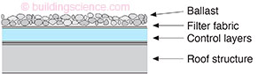
Figure 1: Optimum configuration of control layers for a roof
Flat Roof Assembly
The retrofit assembly consists of the existing ceiling plaster under the roof rafter cavity entirely filled with cellulose insulation. The wall perimeter of the roof rafter cavity is covered with 2” of ccSPF to provide a robust air seal between the existing roof sheathing and the ceiling plane. A strip of pressure treated plywood is installed at the interior vertical face of the parapet to allow for adequate attachment of the air barrier membrane. The air control layer (in a form of the OSB sheathing with integrated water resistive barrier and taped seams) is installed over the existing roof sheathing, with a strip of air barrier membrane at the perimeter of the roof sheathing and the parapet. The new roof sheathing is installed over sleepers (2x lumber ripped with a taper) to provide a consistent slope to drain. Three 2” layers of polyisocyanurate rigid insulation are installed over the air control layer with the joints staggered and the seams taped. Insulation cover board is installed over the rigid insulation, and in turn covered with the roof membrane (which turns up and over the parapet). Cap flashing with drip edges on either side is installed over the parapet.
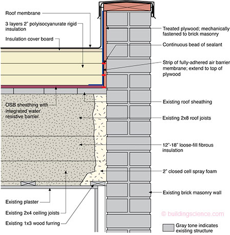
Figure 2: Roof assembly with new roof sheathing as air control layer over existing roof sheathing
ALTERNATELY, if sleepers are not required to provide a consistent slope to drain, a fully- adhered air barrier membrane can be installed over the field of the existing roof sheathing, turned up the parapet, and terminated at the top of plywood.
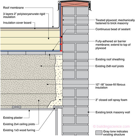
Figure 3: Roof assembly with air barrier membrane over existing roof sheathing
For a wood frame building, a similar combination of air impermeable insulation (either rigid foam boards, Figure 4, or ccSPF, Figure 5) could be used, per details from Lstiburek (2010). The thickness of the air impermeable insulation should be changed based on climate zone. The roof air barrier should remain at the structural sheathing layer; air barrier connections to the wall should be based on the wall’s air barrier strategy.
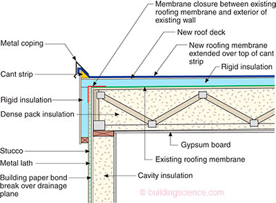
Figure 4: Wood frame roof assembly with rigid foam board exterior insulation (Lstiburek 2010)

Figure 5: Wood frame roof assembly with spray foam exterior-side insulation (Lstiburek 2010)
Water Control Layer
Controlling rainwater is the single most important factor in the design and construction of durable roof assemblies. The fundamental principle of water management is to shed water by layering materials in such a way that water is directed downwards and outwards out of the building or away from the building. The key to this fundamental principle is drainage (Lstiburek 2006b).
Flat roofs should never be flat; therefore, all flat roofs should be tilted and sloped to drains. It is vital that any roof penetrations (drains, skylights or mechanical curbs) are properly flashed, preventing water entry. The materials that form the water control layer(in this case the roof membrane) overlap each other in shingle fashion or are sealed so that water drains down and does not collect on the roof (Lstiburek 2006b).
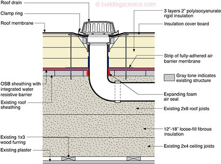
Figure 6: Roof drain water management
Skylights, mechanical curbs and other roof penetrations must be integrated into the roof’s drainage plane (membrane) (Figure 7 and Figure 8). Membranes or formable flashings that line these curbed openings are all elements of drainable systems. These approaches work best when they are sloped inward so the rainwater is directed into the roof drain and taken out of the building. Tobiasson (2009) explicitly recommends interior drainage from low-slope roofs. Draining a membrane over the eaves may have lower first costs, but these eave areas are often the weakest portion of the waterproofing, with leaks commonly developing there. Similar issues are seen with ice damming of scuppers, resulting in roof ponding.
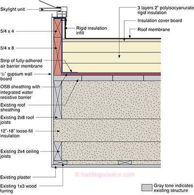
Figure 7: Skylight/mechanical curb water management

Figure 8: PV roof rack blocking water management
It is important to keep rainwater from getting into the top of the parapet. To prevent that, the top of the parapet should slope inward to direct rainwater into the roof drain, and taken off the roof. It is important to ensure that the roof membrane extends up and over the parapet, and under the metal cap flashing, as the cap flashings leak at joints. The flashing should have drip edges— front and back—to prevent staining of the building façade (Lstiburek 2011). . .
Download complete report here.