BSC worked directly with the David Weekley Homes (DWH) – Houston division to redesign three current floor plans in order to locate the heating, ventilation, and air conditioning (HVAC) system in conditioned space. The purpose of this project is to develop a cost-effective design for moving the HVAC system into conditioned space. In addition, BSC conducted energy analysis to calculate the most economical strategy for increasing the energy performance of future production houses. This is in preparation for the upcoming code changes in 2015. The builder wishes to develop an upgrade package that will allow for a seamless transition to the new code mandate.
Executive Summary
BSC worked directly with the David Weekley Homes (DWH) – Houston division to redesign three current floor plans in order to locate the heating, ventilation, and air conditioning (HVAC) system in conditioned space. The purpose of this project is to develop a cost-effective design for moving the HVAC system into conditioned space. In addition, BSC conducted energy analysis to calculate the most economical strategy for increasing the energy performance of future production houses. This is in preparation for the upcoming code changes in 2015. The builder wishes to develop an upgrade package that will allow for a seamless transition to the new code mandate.
The following research questions were addressed by this research project.
- What is the most cost-effective, best-performing, and most easily replicable method of locating ducts inside conditioned space for a hot-humid production home builder that constructs one- and two-story single-family detached residences?
- What is a cost-effective and practical method of achieving 50% source energy savings versus the 2006 International Energy Conservation Code for a hot-humid production builder?
- How accurate are the pre-construction whole house cost estimates compared to confirmed post-construction actual cost?
BSC and the builder developed a duct design strategy that employs a system of dropped ceilings and attic coffers for moving the ductwork from the vented attic to conditioned space. The furnace has been moved to either a mechanical closet in the conditioned living space or a coffered space in the attic.
The development of a design for duct coffers in the attic space allows DWH to embrace the strategy of locating ductwork in conditioned space, in its existing housing stock, without having to rely solely on dropped ceilings. The builder does recognize that a full series of dropped ceilings, without any coffers, would be the most economical strategy for locating ducts. However, the builder perceives this design as having a negative impact on aesthetics and could not be attractive to its customer base. This is one of the more important developments in this research work, as DWH (and its customers) greatly value full ceiling height in the majority of spaces and wish to avoid dropped ceilings as much as possible. The main contribution of this research was to provide a working alternative for builders who wish to move their HVAC systems into conditioned spaces without extended dropped ceilings plus a mechanical closet, or converting to a full unvented cathedralized attic.
Relocating the HVAC system to within conditioned space resulted in significant energy savings toward the goal of achieving 50% energy savings versus the 2006 International Energy Conservation Code. Moving the HVAC system inside conditioned space saves around 4%–5% in source energy use and can reduce the Home Energy Rating System Index by around 4 points. The costs for implementing this duct design strategy on the three research homes was in the range of $6,000–$10,000; however, the builder expects that this figure can improve in future homes to around $4,000–$6,000. This is more affordable compared to the popular strategy of constructing an unvented cathedralized attic with spray polyurethane foam, which for these plans could cost in the range of $10,000–$15,000.
The additional energy upgrades implemented for meeting the 2015 code provision includes improvements to the walls, ceiling, infiltration rate, air conditioner and hot water heater. The predicted costs for these improvements were very accurate compared to the post-construction confirmed costs, as this production builder is adept and experienced with costing specific components.
1 Introduction
1.1 Purpose
Through the advanced new construction energy efficiency packages evaluation in Texas, Building Science Corporation (BSC) seeks to acquire important information about the performance of energy-efficient technology packages designed for a production builder in a hot- humid climate. This research addresses several important gaps and barriers:
- Cost-competitive and replicable designs for locating ducts inside conditioned space by a production builder
- Complete high performance technology packages that will comply with expected future code improvements.
Through this work, BSC expects to collect information about:
- Cost and implementation issues with locating the entire heating, ventilation, and air conditioning (HVAC) system in conditioned space in production homes.
- Comparisons between the various predicted energy savings methodologies available in industry (source energy savings versus the Building America (BA) Benchmark compared to site energy savings provided by commonly used residential modeling software).
The technology package proposed for this pilot community project is most appropriate for single-family detached production houses. From a building science perspective, the Houston package is suitable for other hot-humid production environments. The information gained through this research about the implementation of the technology package at a production community scale and the longer term performance data from the community of houses will support widespread deployment of this package in new housing across the hot-humid climate zone.
The most immediate impact of the research project will be to inform the work of David Weekley Homes (DWH) – Houston. Lessons learned both in the economics of the variations in design and constructability can be applied to the future business model of the production builder.
The adoption of the new and more stringent 2012 International Energy Conservation Code (IECC) is greatly reducing the performance gap between code-built homes and those that are constructed to meet an energy efficiency standard (Bailes 2012). A major component of the 2012 IECC is the mandatory inclusion of the entire HVAC system in conditioned space. This mandate is forcing builders to establish cost-effective strategies for moving the ductwork inside the thermal enclosure. The project also has the potential to impact BA measure guidelines on improving the replicability and cost effectiveness of designs that not only meet the current energy code, but will meet future proposed building code improvements.
This presents a major opportunity for considering the importance of a cost-effective method of locating ducts inside conditioned space in order for production home builders to remain competitive in the market. There is also an opportunity to gauge what house designs will meet the likely 2015 IECC provisional mandate. DWH sees this as part of a long-term strategy for maintaining a high performance design that will be compliant with potential future code provisions. This work will also provide important design and construction data for other production builder in a hot-humid climate as well as for local Home Energy Rating System (HERS) raters and architects.
1.2 Research Questions
The following research questions will be answered by this project.
What is the most cost-effective, best-performing, and most easily replicable method of locating ducts inside conditioned space for a hot-humid production home builder that constructs one- and two-story single-family detached residences?
What is a cost-effective and practical method of achieving 50% source energy savings versus the 2006 IECC for a hot-humid production builder?
How accurate are the pre-construction whole house cost estimates compared to confirmed post-construction actual cost?
1.3 Previous Research
Moving ducts inside conditioned space offers the highest energy savings compared to other energy-related improvements (Lubliner et al. 2008). As energy programs and codes become more stringent, this strategy will need to be implemented more throughout the country.
Previous research has provided guidance and identified risks with duct design strategies, specifically buried ducts (Chasar and Withers 2013; Griffiths et al. 2004). General duct design strategies have been developed for low-energy homes to inform designers and builders (Burdick 2011). Previous studies have calculated potential energy losses due to ducts being located in unconditioned space as being in the range of 25%–40% (Andrews 2003), thus prioritizing the need for developing affordable strategies for moving the HVAC system within the thermal enclosure.
Many of the whole-house characteristics for these homes are connected to previous research work on advanced framing, the effectiveness of ventilation systems, and other whole-house energy efficiency packages for affordable housing as described below.
The enclosure included in the Houston energy efficiency package uses advanced framing (BSC 2009; Lstiburek and Grin 2010) and insulating sheathing as the primary thermal control layer and the drainage plane (Baker 2006; BSC 2007).
This work also draws on whole house energy efficiency research work that has been published by BSC the Builder’s Field Guides series (Lstiburek 2005) and in research reports on community scale evaluations in hot-humid and other climate zones (BSC 2010).
The package specifies a central fan integrated ventilation supply (CFIS) system that has been extensively researched and tested by BSC (Rudd 2008; Hendron et al. 2008).
1.4 Whole-House Specifications
Figure 1 through Figure 3 show the front elevation of the three research houses for this project.
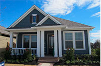
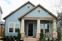

Figure 1. Plan 4127 (above left); Figure 2. Plan 4128 (above middle); Figure 3. Plan 4069 (above right)
Table 1 lists the general dimensions and areas for each of the three floor plans.
Table 1. Floor Plan Dimensions and Areas
Floor | # Floors | Floor Area | Surface Area (ft2) | Volume (ft3) | Beds (ct) | Baths (ct) | Glazing Ratio |
| 4127 | 1 | 1,757 | 5,875 | 17,570 | 3 | 2.0 | 17.0% |
| 4128 | 2 | 2,179 | 5,729 | 21,090 | 3 | 2.5 | 12.7% |
| 4069 | 2 | 4,169 | 8,833 | 39,474 | 5 | 3.5 | 13.8% |
Table 2 lists the characteristics for the three DWH research homes. Whole-house energy analysis was performed on each of the three homes. This includes a prediction of source energy savings with the characteristics found in Table 2. This analysis can be found in the appendix.
Table 2. Summary of DWH-Houston Energy Efficiency Package Components
| Enclosure | Specifications |
| Roof | |
| Description | Dark color asphalt shingles on rafter roof – vented attic |
| Insulation | R-50 blown fiberglass |
| Walls | |
| Description | 2 × 6 @ 24 in. o.c. with advanced framing with insulating sheathing |
| Insulation | R-19 fiberglass batts with R-3.75 ¾-in. XPSa insulating sheathing |
| Foundation | |
| Description | Slab on grade |
| Insulation | Uninsulated |
| Windows | |
| Description | Double pane vinyl framed with LoE3 spectrally selective glazing |
| U-Value | U = 0.29 |
| SHGCb | SHGC = 0.22 |
| Infiltration | |
| Specification | 0.25 CFM 50/ft2 enclosure @ 50 Pa |
| Performance Test | Average = 0.22 CFM 50/ft2 enclosure @ 50 Pa |
| Mechanical Systems | Specifications |
| Heating | |
| Description | 96% AFUEc natural gas furnace |
| Manufacturer and Model | Lennox |
| Cooling | |
| Description | 16 SEERd two-stage air conditioner |
| Manufacturer and Model | Lennox |
| Domestic Hot Water | |
| Description | Tank gas water heater (EFe = 0.62) |
| Manufacturer and Model | Rheem |
| Distribution | |
| Description | R-6 flex ducts in conditioned space |
| Leakage | Maximum 5% duct leakage to outside |
| Ventilation | |
| Description | Central fan integrated supply-only system with fan cycler 33% Duty cycle: 10 minutes on; 20 minutes off, 50 CFM flow |
| Manufacturer and Model | Aprilaire 8126 Ventilation Control System fan cycler |
| Return Pathways | |
| Description | Mostly jump ducts in bedrooms and study; some active returns in master suites |
c Annual fuel utilization efficiency
d Seasonal energy efficiency ratio
2 Development of Duct Strategy
BSC visited DWH – Houston in August 2012 and met with representatives from DWH and Davis Air Conditioning (HVAC contractor). An initial meeting was conducted to discuss and develop a proposed duct design strategy. Three homes currently under construction, representing a range of DWH house and HVAC system types, were toured over a 2-day period to be used as examples for developing strategies for locating ducts within conditioned space.
2.1 Initial Design Development
A number of strategies exist for locating ducts within conditioned space. Figure 4 shows Duct design strategy 1: Dropped ceiling and mechanical closet. In this strategy, the air handling unit (AHU) is located in a mechanical closet in the living space and all of the ductwork is located in a series of strategically placed dropped ceilings. The main benefit to this design is that the attic remains a typical vented attic and traditional insulation (e.g., fiberglass or cellulose) can be installed. The air barrier remains a two-dimensional plane, without any duct penetrations, which is the most simplified air barrier geometry (red line in Figure 4). This strategy is the most economical out of all the strategies discussed.
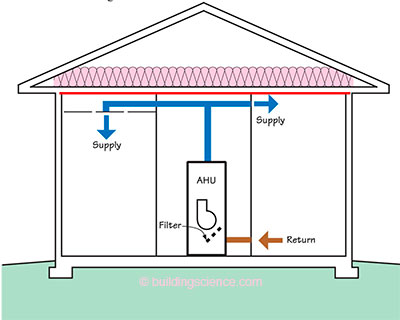
Figure 4. Duct design strategy 1—Dropped ceilings and mechanical closet
Negatives associated with this strategy include: conditioned floor area lost due to mechanical closet, reduced architectural aesthetics with lowered ceiling level, and potential noise from the mechanical closet.
The risk of AHU closet noise can be abated by implementing the following measures:
- Installing a variable-speed AHU or furnace with an electronically commutated motor, as these motors are quieter than traditional permanent split capacitor motors.
- Installing a weather-stripped door at the mechanical closet
- Designing the duct system to operate at low velocities in the supply and return plenums. BSC recommends designing the supply plenum for 500–750 ft/min and the return plenum at 250–550 ft/min. Also, velocities at the return grille should not exceed 350 ft/min to prevent whistling (Rudd 2006).
Despite the drawbacks, this is a very popular strategy with builders and is the best performing design from an energy standpoint. . .
Donwload the complete report here.