The primary purpose of this field test was to characterize the uniformity of room-to-room ventilation air distribution under various operating conditions by examining multi-zone tracer gas decay curves and calculating local age-of-air. The tests were conducted in two Sacramento houses, and were designed to allow direct, quantitative comparisons of various ventilation approaches, which could potentially be factored into ventilation rate trade-offs in future updates to ASHRAE Standard 62.2. Analysis of the measured data showed that reciprocal age-of-air analysis worked well to characterize room-to-room uniformity of ventilation air distribution as long as the house was well mixed at the beginning of the test, and weather conditions were sufficiently steady-state.
Introduction
ASHRAE Standard 62.2 (ASHRAE 2004), "Ventilation and Acceptable Indoor Air Quality in Low-Rise Residential Buildings," specifies a minimum ventilation flow rate that depends on the timing of ventilation air delivery but it is silent on whole-house distribution of ventilation air. The Washington State Ventilation and Indoor Air Quality Code (WAC 2004) is also silent regarding ventilation air distribution. Both the Minnesota Building Code (MN Chapter 7672) and the National Building Code of Canada (NBC 2005) referring to Canadian Standard F326-M91 (CSA 2005) require whole-house ventilation air distribution by means of fully ducted ventilation systems or by mixing via a central air handling system. A large, U.S. private-sector, high-performance home program also requires periodic central air handler operation to assure whole-house mixing for ventilation air distribution and thermal comfort. Prior work by Rudd (2000) showed that ventilation systems that utilized whole-house distribution and mixing via the central air handling system had much less room-to-room variation in ventilation air exchange than systems that did not.
This research program evaluated the distribution of ventilation air in two new test houses using several different ventilation system configurations and air-mixing scenarios. The test program was conducted in late December 2005 and early January 2006, during relatively mild winter weather in Sacramento. The first test house was a one-story model with four bedrooms. The second was a two-story model, also with four bedrooms. Both houses were designed to be energy efficient, had slab-on-grade foundations, ducts in conditioned space, and met the builder’s airtightness target measured with a blower door (2 effective leakage area per 100 ft2 envelope area). Other key specifications for both houses are summarized in Table 1, and photos are shown in Figures 1 and 2. Floor plans are shown in Figures 3 and 4.
Table 1: Specifications for DR Horton test houses
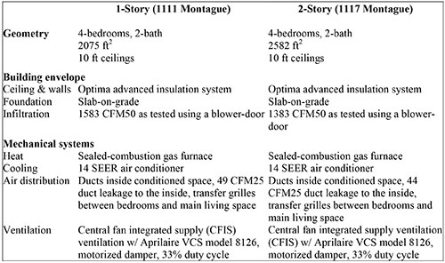
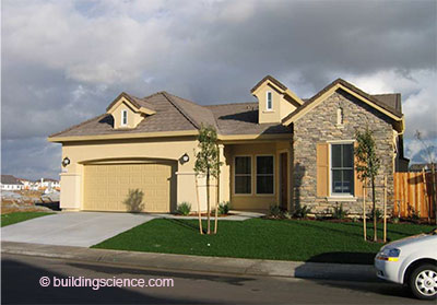
Figure 1: DR Horton 1-story test house (1111 Montague)
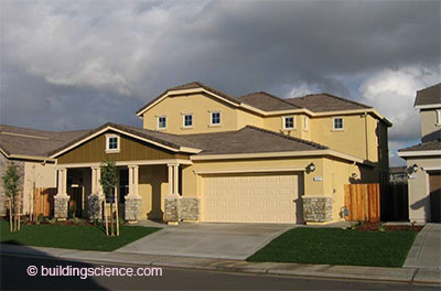
Figure 2: DR Horton 2-story test house (1117 Montague)
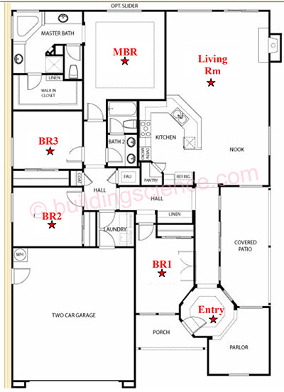
Figure 3: 1-story test house floor plan (1111 Montague)
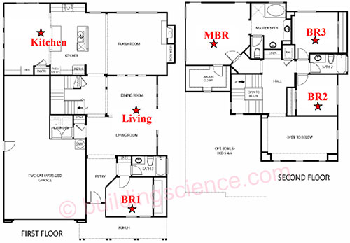
Figure 4: 2-story test house floor plan (mirror image of 1117 Montague)
The primary purpose of this test program was to characterize the uniformity of room-to-room distribution of outside air under various conditions by examining multi-zone tracer gas decay curves. In order for dilution ventilation systems to provide predictable results independent of the geometry of individual homes, outside air must be uniformly distributed throughout the house. The tests in the Sacramento houses were designed to allow direct, quantitative comparisons of various ventilation approaches, which could potentially be factored into ventilation rate trade-offs in future updates to ASHRAE Standard 62.2 (ASHRAE 2004).
Test Plan
Research Questions
The following series of research questions were identified by the researchers to quantify the ventilation distribution characteristics of the test houses under various operating conditions:
- What is the natural air change rate (ACH) for each house with bedroom doors open, no air handler operation, and no mechanical ventilation? What is the room-to-room uniformity in outside air distribution?
- What is the change in whole-house ACH caused by air handler operation? What is the change in room-to-room uniformity of outside air distribution?
- What is the change in whole-house ACH caused by closing the bedroom doors? What is the change in room-to-room uniformity of outside air distribution?
- What is the change in whole-house ACH caused by taping over the transfer grilles? What is the change in room-to-room uniformity of outside air distribution?
- What is the difference in whole-house ACH for a central-fan integrated supply ventilation system (CFIS) operating at 33% duty cycle compared to a continuous exhaust ventilation system, with both systems meeting the ASHRAE 62.2 recommended minimum ventilation rate on average? How does the resulting room-to-room uniformity of outside air distribution compare?
- How does the whole-house ACH and uniformity of outside air distribution change for a CFIS ventilation system when the ventilation rate is lowered from 100% of the ASHRAE 62.2 recommendation to 60% and to 33%?
- How does the whole-house ACH and uniformity of outside air distribution change for the continuous exhaust ventilation system when the location of the exhaust port is changed from the utility room to the master bathroom?
- How uniform is the outside air distribution for the two-story house compared to the onestory house?
Test Set-Up
Single-tracer gas decay with multi-zone sampling was used to evaluate the performance of each ventilation system based on how uniformly outside air was distributed to each room or zone within the house. The decay curves demonstrate the rate at which the tracer gas (representing a pollutant), which is initially distributed uniformly throughout the house, is diluted within each zone, as a result of outside air that enters the zone directly as well as air that is exchanged among zones. Air entering one zone from another may contain either a higher or lower concentration of the tracer than the air already in the zone. This test method is designed as a practical method to evaluate the uniformity of ventilation air distribution within a home, assuming that dangerous pollutants such as radon are controlled using appropriate source mitigation strategies. Uniform distribution of outside air is required for dilution ventilation systems to provide predictable results independent of the geometry of individual homes.
A multi-zone tracer gas sampling system was installed in each house for the test. This equipment consisted of a Bruel and Kjaer model 1302 multi-gas monitor and a model 1303 multi-point sampler, as shown in Figure 5. Sample tubes were placed in six locations in each house and attached to the multi-point sampler. The six sampled locations are designated with red stars on the floor plans in Figures 3 and 4. The sampler was programmed to draw a sample from each sequential location at an interval of about 2 minutes; thus all six locations were sampled at an interval of about 12 minutes.
The air sample in each zone was taken near the center of the room at a height of four feet above the floor. The zone air temperature was measured at the same location. The local zone air temperature measurement was used to control the electric heater in each zone (see Test Procedure section below) to achieve a uniform and constant air temperature throughout the house. Mixing fans were used to maintain uniform temperatures and concentrations within each room. . .
Download complete report here.